EP0853824B1 - Flow field structures for membrane electrode assemblies of fuel cells - Google Patents
Flow field structures for membrane electrode assemblies of fuel cells Download PDFInfo
- Publication number
- EP0853824B1 EP0853824B1 EP96936178A EP96936178A EP0853824B1 EP 0853824 B1 EP0853824 B1 EP 0853824B1 EP 96936178 A EP96936178 A EP 96936178A EP 96936178 A EP96936178 A EP 96936178A EP 0853824 B1 EP0853824 B1 EP 0853824B1
- Authority
- EP
- European Patent Office
- Prior art keywords
- flow field
- fuel cell
- percent
- layer
- membrane
- Prior art date
- Legal status (The legal status is an assumption and is not a legal conclusion. Google has not performed a legal analysis and makes no representation as to the accuracy of the status listed.)
- Expired - Lifetime
Links
- 239000012528 membrane Substances 0.000 title claims abstract description 71
- 239000000446 fuel Substances 0.000 title claims abstract description 70
- 230000000712 assembly Effects 0.000 title description 3
- 238000000429 assembly Methods 0.000 title description 3
- 239000011148 porous material Substances 0.000 claims abstract description 112
- 239000002245 particle Substances 0.000 claims description 49
- XLYOFNOQVPJJNP-UHFFFAOYSA-N water Substances O XLYOFNOQVPJJNP-UHFFFAOYSA-N 0.000 claims description 43
- 239000000463 material Substances 0.000 claims description 30
- 239000007787 solid Substances 0.000 claims description 30
- 229920000642 polymer Polymers 0.000 claims description 25
- 239000003575 carbonaceous material Substances 0.000 claims description 13
- 229920001343 polytetrafluoroethylene Polymers 0.000 claims description 12
- 125000000542 sulfonic acid group Chemical group 0.000 claims description 7
- 229920005597 polymer membrane Polymers 0.000 claims description 2
- 210000004027 cell Anatomy 0.000 description 64
- 239000000203 mixture Substances 0.000 description 62
- 239000000976 ink Substances 0.000 description 60
- 229920000554 ionomer Polymers 0.000 description 34
- OKTJSMMVPCPJKN-UHFFFAOYSA-N Carbon Chemical compound [C] OKTJSMMVPCPJKN-UHFFFAOYSA-N 0.000 description 28
- 239000007789 gas Substances 0.000 description 28
- 239000003054 catalyst Substances 0.000 description 26
- 238000000034 method Methods 0.000 description 26
- BASFCYQUMIYNBI-UHFFFAOYSA-N platinum Chemical compound [Pt] BASFCYQUMIYNBI-UHFFFAOYSA-N 0.000 description 22
- 229910052799 carbon Inorganic materials 0.000 description 21
- 239000005518 polymer electrolyte Substances 0.000 description 18
- 239000011230 binding agent Substances 0.000 description 15
- -1 polytetrafluoroethylene Polymers 0.000 description 15
- OKKJLVBELUTLKV-UHFFFAOYSA-N Methanol Chemical compound OC OKKJLVBELUTLKV-UHFFFAOYSA-N 0.000 description 12
- 238000002360 preparation method Methods 0.000 description 11
- 229920002313 fluoropolymer Polymers 0.000 description 10
- 230000002209 hydrophobic effect Effects 0.000 description 10
- 239000007788 liquid Substances 0.000 description 10
- 229910052697 platinum Inorganic materials 0.000 description 10
- 239000004810 polytetrafluoroethylene Substances 0.000 description 10
- 239000000376 reactant Substances 0.000 description 10
- 150000002894 organic compounds Chemical class 0.000 description 9
- 229920000049 Carbon (fiber) Polymers 0.000 description 8
- 239000004917 carbon fiber Substances 0.000 description 8
- 239000004811 fluoropolymer Substances 0.000 description 8
- 229910002804 graphite Inorganic materials 0.000 description 8
- 239000010439 graphite Substances 0.000 description 8
- 239000002904 solvent Substances 0.000 description 8
- VDZOOKBUILJEDG-UHFFFAOYSA-M tetrabutylammonium hydroxide Chemical compound [OH-].CCCC[N+](CCCC)(CCCC)CCCC VDZOOKBUILJEDG-UHFFFAOYSA-M 0.000 description 8
- 239000002585 base Substances 0.000 description 7
- 239000002131 composite material Substances 0.000 description 7
- RUOJZAUFBMNUDX-UHFFFAOYSA-N propylene carbonate Chemical compound CC1COC(=O)O1 RUOJZAUFBMNUDX-UHFFFAOYSA-N 0.000 description 7
- 239000002253 acid Substances 0.000 description 6
- 230000003197 catalytic effect Effects 0.000 description 6
- 150000001875 compounds Chemical class 0.000 description 6
- 150000003839 salts Chemical group 0.000 description 6
- 238000011068 loading method Methods 0.000 description 5
- VNWKTOKETHGBQD-UHFFFAOYSA-N methane Chemical compound C VNWKTOKETHGBQD-UHFFFAOYSA-N 0.000 description 5
- 230000001590 oxidative effect Effects 0.000 description 5
- 125000005010 perfluoroalkyl group Chemical group 0.000 description 5
- 239000000758 substrate Substances 0.000 description 5
- CSCPPACGZOOCGX-UHFFFAOYSA-N Acetone Chemical compound CC(C)=O CSCPPACGZOOCGX-UHFFFAOYSA-N 0.000 description 4
- UFHFLCQGNIYNRP-UHFFFAOYSA-N Hydrogen Chemical compound [H][H] UFHFLCQGNIYNRP-UHFFFAOYSA-N 0.000 description 4
- KDLHZDBZIXYQEI-UHFFFAOYSA-N Palladium Chemical compound [Pd] KDLHZDBZIXYQEI-UHFFFAOYSA-N 0.000 description 4
- 238000009792 diffusion process Methods 0.000 description 4
- 229910052739 hydrogen Inorganic materials 0.000 description 4
- 239000001257 hydrogen Substances 0.000 description 4
- 229910052751 metal Inorganic materials 0.000 description 4
- 239000002184 metal Substances 0.000 description 4
- 238000002156 mixing Methods 0.000 description 4
- 239000003960 organic solvent Substances 0.000 description 4
- 239000007800 oxidant agent Substances 0.000 description 4
- WEVYAHXRMPXWCK-UHFFFAOYSA-N Acetonitrile Chemical compound CC#N WEVYAHXRMPXWCK-UHFFFAOYSA-N 0.000 description 3
- YCKRFDGAMUMZLT-UHFFFAOYSA-N Fluorine atom Chemical compound [F] YCKRFDGAMUMZLT-UHFFFAOYSA-N 0.000 description 3
- HEMHJVSKTPXQMS-UHFFFAOYSA-M Sodium hydroxide Chemical compound [OH-].[Na+] HEMHJVSKTPXQMS-UHFFFAOYSA-M 0.000 description 3
- 229920006243 acrylic copolymer Polymers 0.000 description 3
- QVGXLLKOCUKJST-UHFFFAOYSA-N atomic oxygen Chemical compound [O] QVGXLLKOCUKJST-UHFFFAOYSA-N 0.000 description 3
- 238000009835 boiling Methods 0.000 description 3
- 239000007795 chemical reaction product Substances 0.000 description 3
- 239000011152 fibreglass Substances 0.000 description 3
- 239000000945 filler Substances 0.000 description 3
- 229910052731 fluorine Inorganic materials 0.000 description 3
- 239000011737 fluorine Substances 0.000 description 3
- 238000005342 ion exchange Methods 0.000 description 3
- 125000003010 ionic group Chemical group 0.000 description 3
- BCCOBQSFUDVTJQ-UHFFFAOYSA-N octafluorocyclobutane Chemical class FC1(F)C(F)(F)C(F)(F)C1(F)F BCCOBQSFUDVTJQ-UHFFFAOYSA-N 0.000 description 3
- 235000019407 octafluorocyclobutane Nutrition 0.000 description 3
- 229910052760 oxygen Inorganic materials 0.000 description 3
- 239000001301 oxygen Substances 0.000 description 3
- 239000011734 sodium Substances 0.000 description 3
- ZZXUZKXVROWEIF-UHFFFAOYSA-N 1,2-butylene carbonate Chemical compound CCC1COC(=O)O1 ZZXUZKXVROWEIF-UHFFFAOYSA-N 0.000 description 2
- GOYDNIKZWGIXJT-UHFFFAOYSA-N 1,2-difluorobenzene Chemical compound FC1=CC=CC=C1F GOYDNIKZWGIXJT-UHFFFAOYSA-N 0.000 description 2
- LFQSCWFLJHTTHZ-UHFFFAOYSA-N Ethanol Chemical compound CCO LFQSCWFLJHTTHZ-UHFFFAOYSA-N 0.000 description 2
- KMTRUDSVKNLOMY-UHFFFAOYSA-N Ethylene carbonate Chemical compound O=C1OCCO1 KMTRUDSVKNLOMY-UHFFFAOYSA-N 0.000 description 2
- PEDCQBHIVMGVHV-UHFFFAOYSA-N Glycerine Chemical compound OCC(O)CO PEDCQBHIVMGVHV-UHFFFAOYSA-N 0.000 description 2
- DGAQECJNVWCQMB-PUAWFVPOSA-M Ilexoside XXIX Chemical compound C[C@@H]1CC[C@@]2(CC[C@@]3(C(=CC[C@H]4[C@]3(CC[C@@H]5[C@@]4(CC[C@@H](C5(C)C)OS(=O)(=O)[O-])C)C)[C@@H]2[C@]1(C)O)C)C(=O)O[C@H]6[C@@H]([C@H]([C@@H]([C@H](O6)CO)O)O)O.[Na+] DGAQECJNVWCQMB-PUAWFVPOSA-M 0.000 description 2
- WHXSMMKQMYFTQS-UHFFFAOYSA-N Lithium Chemical compound [Li] WHXSMMKQMYFTQS-UHFFFAOYSA-N 0.000 description 2
- ZLMJMSJWJFRBEC-UHFFFAOYSA-N Potassium Chemical compound [K] ZLMJMSJWJFRBEC-UHFFFAOYSA-N 0.000 description 2
- KJTLSVCANCCWHF-UHFFFAOYSA-N Ruthenium Chemical compound [Ru] KJTLSVCANCCWHF-UHFFFAOYSA-N 0.000 description 2
- VYPSYNLAJGMNEJ-UHFFFAOYSA-N Silicium dioxide Chemical compound O=[Si]=O VYPSYNLAJGMNEJ-UHFFFAOYSA-N 0.000 description 2
- QAOWNCQODCNURD-UHFFFAOYSA-N Sulfuric acid Chemical compound OS(O)(=O)=O QAOWNCQODCNURD-UHFFFAOYSA-N 0.000 description 2
- 229910052783 alkali metal Inorganic materials 0.000 description 2
- 150000001340 alkali metals Chemical class 0.000 description 2
- 239000000956 alloy Substances 0.000 description 2
- 229910045601 alloy Inorganic materials 0.000 description 2
- 230000008901 benefit Effects 0.000 description 2
- IKYMJBKVGYKTMX-UHFFFAOYSA-N carbamic acid;ethene Chemical compound C=C.NC(O)=O IKYMJBKVGYKTMX-UHFFFAOYSA-N 0.000 description 2
- IRBFQENXOFCNSG-UHFFFAOYSA-N carbamic acid;prop-1-ene Chemical compound CC=C.NC(O)=O IRBFQENXOFCNSG-UHFFFAOYSA-N 0.000 description 2
- 239000006229 carbon black Substances 0.000 description 2
- 230000015556 catabolic process Effects 0.000 description 2
- 239000003795 chemical substances by application Substances 0.000 description 2
- 239000011248 coating agent Substances 0.000 description 2
- 238000000576 coating method Methods 0.000 description 2
- 239000011231 conductive filler Substances 0.000 description 2
- 239000004020 conductor Substances 0.000 description 2
- 238000006731 degradation reaction Methods 0.000 description 2
- 239000006185 dispersion Substances 0.000 description 2
- 238000009826 distribution Methods 0.000 description 2
- 238000006056 electrooxidation reaction Methods 0.000 description 2
- 238000005516 engineering process Methods 0.000 description 2
- PCHJSUWPFVWCPO-UHFFFAOYSA-N gold Chemical compound [Au] PCHJSUWPFVWCPO-UHFFFAOYSA-N 0.000 description 2
- 229910052737 gold Inorganic materials 0.000 description 2
- 239000010931 gold Substances 0.000 description 2
- 229910052736 halogen Inorganic materials 0.000 description 2
- 150000002367 halogens Chemical group 0.000 description 2
- 238000010438 heat treatment Methods 0.000 description 2
- 229910052741 iridium Inorganic materials 0.000 description 2
- GKOZUEZYRPOHIO-UHFFFAOYSA-N iridium atom Chemical compound [Ir] GKOZUEZYRPOHIO-UHFFFAOYSA-N 0.000 description 2
- 238000010030 laminating Methods 0.000 description 2
- 239000004816 latex Substances 0.000 description 2
- 229920000126 latex Polymers 0.000 description 2
- 229910052744 lithium Inorganic materials 0.000 description 2
- QSHDDOUJBYECFT-UHFFFAOYSA-N mercury Chemical compound [Hg] QSHDDOUJBYECFT-UHFFFAOYSA-N 0.000 description 2
- 229910052753 mercury Inorganic materials 0.000 description 2
- 230000003647 oxidation Effects 0.000 description 2
- 238000007254 oxidation reaction Methods 0.000 description 2
- 238000006213 oxygenation reaction Methods 0.000 description 2
- 229910052763 palladium Inorganic materials 0.000 description 2
- 229920000767 polyaniline Polymers 0.000 description 2
- 229920000128 polypyrrole Polymers 0.000 description 2
- 238000002459 porosimetry Methods 0.000 description 2
- 229910052700 potassium Inorganic materials 0.000 description 2
- 239000011591 potassium Substances 0.000 description 2
- 239000000843 powder Substances 0.000 description 2
- 125000001453 quaternary ammonium group Chemical group 0.000 description 2
- 229910052703 rhodium Inorganic materials 0.000 description 2
- 239000010948 rhodium Substances 0.000 description 2
- MHOVAHRLVXNVSD-UHFFFAOYSA-N rhodium atom Chemical compound [Rh] MHOVAHRLVXNVSD-UHFFFAOYSA-N 0.000 description 2
- 229910052707 ruthenium Inorganic materials 0.000 description 2
- ABTOQLMXBSRXSM-UHFFFAOYSA-N silicon tetrafluoride Chemical compound F[Si](F)(F)F ABTOQLMXBSRXSM-UHFFFAOYSA-N 0.000 description 2
- 229910052708 sodium Inorganic materials 0.000 description 2
- HXJUTPCZVOIRIF-UHFFFAOYSA-N sulfolane Chemical compound O=S1(=O)CCCC1 HXJUTPCZVOIRIF-UHFFFAOYSA-N 0.000 description 2
- 239000000725 suspension Substances 0.000 description 2
- 238000012360 testing method Methods 0.000 description 2
- 238000004448 titration Methods 0.000 description 2
- 238000012546 transfer Methods 0.000 description 2
- 229910052723 transition metal Inorganic materials 0.000 description 2
- 150000003624 transition metals Chemical class 0.000 description 2
- LCPVQAHEFVXVKT-UHFFFAOYSA-N 2-(2,4-difluorophenoxy)pyridin-3-amine Chemical compound NC1=CC=CN=C1OC1=CC=C(F)C=C1F LCPVQAHEFVXVKT-UHFFFAOYSA-N 0.000 description 1
- MYMOFIZGZYHOMD-UHFFFAOYSA-N Dioxygen Chemical compound O=O MYMOFIZGZYHOMD-UHFFFAOYSA-N 0.000 description 1
- 239000004793 Polystyrene Substances 0.000 description 1
- RTAQQCXQSZGOHL-UHFFFAOYSA-N Titanium Chemical compound [Ti] RTAQQCXQSZGOHL-UHFFFAOYSA-N 0.000 description 1
- 238000009825 accumulation Methods 0.000 description 1
- 230000002411 adverse Effects 0.000 description 1
- 238000005054 agglomeration Methods 0.000 description 1
- 230000002776 aggregation Effects 0.000 description 1
- 150000001298 alcohols Chemical class 0.000 description 1
- PNEYBMLMFCGWSK-UHFFFAOYSA-N aluminium oxide Inorganic materials [O-2].[O-2].[O-2].[Al+3].[Al+3] PNEYBMLMFCGWSK-UHFFFAOYSA-N 0.000 description 1
- UMIVXZPTRXBADB-UHFFFAOYSA-N benzocyclobutene Chemical class C1=CC=C2CCC2=C1 UMIVXZPTRXBADB-UHFFFAOYSA-N 0.000 description 1
- 230000005540 biological transmission Effects 0.000 description 1
- 150000001721 carbon Chemical group 0.000 description 1
- 210000000170 cell membrane Anatomy 0.000 description 1
- 238000006243 chemical reaction Methods 0.000 description 1
- 230000006835 compression Effects 0.000 description 1
- 238000007906 compression Methods 0.000 description 1
- 238000009833 condensation Methods 0.000 description 1
- 230000005494 condensation Effects 0.000 description 1
- 229920001940 conductive polymer Polymers 0.000 description 1
- 239000012809 cooling fluid Substances 0.000 description 1
- 238000004132 cross linking Methods 0.000 description 1
- 230000003247 decreasing effect Effects 0.000 description 1
- 238000006073 displacement reaction Methods 0.000 description 1
- 239000012153 distilled water Substances 0.000 description 1
- 238000003487 electrochemical reaction Methods 0.000 description 1
- 239000003792 electrolyte Substances 0.000 description 1
- 239000003822 epoxy resin Substances 0.000 description 1
- UQSQSQZYBQSBJZ-UHFFFAOYSA-N fluorosulfonic acid Chemical compound OS(F)(=O)=O UQSQSQZYBQSBJZ-UHFFFAOYSA-N 0.000 description 1
- 235000011187 glycerol Nutrition 0.000 description 1
- LNEPOXFFQSENCJ-UHFFFAOYSA-N haloperidol Chemical compound C1CC(O)(C=2C=CC(Cl)=CC=2)CCN1CCCC(=O)C1=CC=C(F)C=C1 LNEPOXFFQSENCJ-UHFFFAOYSA-N 0.000 description 1
- 230000003301 hydrolyzing effect Effects 0.000 description 1
- 238000010348 incorporation Methods 0.000 description 1
- 239000003014 ion exchange membrane Substances 0.000 description 1
- 238000003475 lamination Methods 0.000 description 1
- 238000004519 manufacturing process Methods 0.000 description 1
- 238000005259 measurement Methods 0.000 description 1
- 238000010422 painting Methods 0.000 description 1
- 239000002798 polar solvent Substances 0.000 description 1
- 229920000233 poly(alkylene oxides) Polymers 0.000 description 1
- 239000004417 polycarbonate Substances 0.000 description 1
- 229920000515 polycarbonate Polymers 0.000 description 1
- 229920000647 polyepoxide Polymers 0.000 description 1
- 229920000098 polyolefin Polymers 0.000 description 1
- 229920002223 polystyrene Polymers 0.000 description 1
- 229920002451 polyvinyl alcohol Polymers 0.000 description 1
- 235000019422 polyvinyl alcohol Nutrition 0.000 description 1
- 238000010248 power generation Methods 0.000 description 1
- 230000008569 process Effects 0.000 description 1
- 239000000047 product Substances 0.000 description 1
- 238000012216 screening Methods 0.000 description 1
- 150000004760 silicates Chemical class 0.000 description 1
- 239000000377 silicon dioxide Substances 0.000 description 1
- YPNVIBVEFVRZPJ-UHFFFAOYSA-L silver sulfate Chemical compound [Ag+].[Ag+].[O-]S([O-])(=O)=O YPNVIBVEFVRZPJ-UHFFFAOYSA-L 0.000 description 1
- 229910000367 silver sulfate Inorganic materials 0.000 description 1
- CHQMHPLRPQMAMX-UHFFFAOYSA-L sodium persulfate Substances [Na+].[Na+].[O-]S(=O)(=O)OOS([O-])(=O)=O CHQMHPLRPQMAMX-UHFFFAOYSA-L 0.000 description 1
- 238000007614 solvation Methods 0.000 description 1
- 239000010935 stainless steel Substances 0.000 description 1
- 229910001220 stainless steel Inorganic materials 0.000 description 1
- 238000003756 stirring Methods 0.000 description 1
- 239000000126 substance Substances 0.000 description 1
- 125000000472 sulfonyl group Chemical group *S(*)(=O)=O 0.000 description 1
- 229920001169 thermoplastic Polymers 0.000 description 1
- 229920001187 thermosetting polymer Polymers 0.000 description 1
- 239000004416 thermosoftening plastic Substances 0.000 description 1
- 229910052719 titanium Inorganic materials 0.000 description 1
- 239000010936 titanium Substances 0.000 description 1
- 238000005303 weighing Methods 0.000 description 1
Images


Classifications
-
- H—ELECTRICITY
- H01—ELECTRIC ELEMENTS
- H01M—PROCESSES OR MEANS, e.g. BATTERIES, FOR THE DIRECT CONVERSION OF CHEMICAL ENERGY INTO ELECTRICAL ENERGY
- H01M4/00—Electrodes
- H01M4/86—Inert electrodes with catalytic activity, e.g. for fuel cells
- H01M4/88—Processes of manufacture
-
- H—ELECTRICITY
- H01—ELECTRIC ELEMENTS
- H01M—PROCESSES OR MEANS, e.g. BATTERIES, FOR THE DIRECT CONVERSION OF CHEMICAL ENERGY INTO ELECTRICAL ENERGY
- H01M4/00—Electrodes
- H01M4/86—Inert electrodes with catalytic activity, e.g. for fuel cells
- H01M4/88—Processes of manufacture
- H01M4/8825—Methods for deposition of the catalytic active composition
- H01M4/8828—Coating with slurry or ink
-
- H—ELECTRICITY
- H01—ELECTRIC ELEMENTS
- H01M—PROCESSES OR MEANS, e.g. BATTERIES, FOR THE DIRECT CONVERSION OF CHEMICAL ENERGY INTO ELECTRICAL ENERGY
- H01M4/00—Electrodes
- H01M4/86—Inert electrodes with catalytic activity, e.g. for fuel cells
-
- H—ELECTRICITY
- H01—ELECTRIC ELEMENTS
- H01M—PROCESSES OR MEANS, e.g. BATTERIES, FOR THE DIRECT CONVERSION OF CHEMICAL ENERGY INTO ELECTRICAL ENERGY
- H01M4/00—Electrodes
- H01M4/86—Inert electrodes with catalytic activity, e.g. for fuel cells
- H01M4/88—Processes of manufacture
- H01M4/8803—Supports for the deposition of the catalytic active composition
- H01M4/8807—Gas diffusion layers
-
- H—ELECTRICITY
- H01—ELECTRIC ELEMENTS
- H01M—PROCESSES OR MEANS, e.g. BATTERIES, FOR THE DIRECT CONVERSION OF CHEMICAL ENERGY INTO ELECTRICAL ENERGY
- H01M4/00—Electrodes
- H01M4/86—Inert electrodes with catalytic activity, e.g. for fuel cells
- H01M4/90—Selection of catalytic material
- H01M4/92—Metals of platinum group
- H01M4/925—Metals of platinum group supported on carriers, e.g. powder carriers
- H01M4/926—Metals of platinum group supported on carriers, e.g. powder carriers on carbon or graphite
-
- H—ELECTRICITY
- H01—ELECTRIC ELEMENTS
- H01M—PROCESSES OR MEANS, e.g. BATTERIES, FOR THE DIRECT CONVERSION OF CHEMICAL ENERGY INTO ELECTRICAL ENERGY
- H01M8/00—Fuel cells; Manufacture thereof
- H01M8/02—Details
-
- H—ELECTRICITY
- H01—ELECTRIC ELEMENTS
- H01M—PROCESSES OR MEANS, e.g. BATTERIES, FOR THE DIRECT CONVERSION OF CHEMICAL ENERGY INTO ELECTRICAL ENERGY
- H01M8/00—Fuel cells; Manufacture thereof
- H01M8/02—Details
- H01M8/0202—Collectors; Separators, e.g. bipolar separators; Interconnectors
- H01M8/023—Porous and characterised by the material
- H01M8/0234—Carbonaceous material
-
- H—ELECTRICITY
- H01—ELECTRIC ELEMENTS
- H01M—PROCESSES OR MEANS, e.g. BATTERIES, FOR THE DIRECT CONVERSION OF CHEMICAL ENERGY INTO ELECTRICAL ENERGY
- H01M8/00—Fuel cells; Manufacture thereof
- H01M8/02—Details
- H01M8/0202—Collectors; Separators, e.g. bipolar separators; Interconnectors
- H01M8/023—Porous and characterised by the material
- H01M8/0239—Organic resins; Organic polymers
-
- H—ELECTRICITY
- H01—ELECTRIC ELEMENTS
- H01M—PROCESSES OR MEANS, e.g. BATTERIES, FOR THE DIRECT CONVERSION OF CHEMICAL ENERGY INTO ELECTRICAL ENERGY
- H01M8/00—Fuel cells; Manufacture thereof
- H01M8/02—Details
- H01M8/0202—Collectors; Separators, e.g. bipolar separators; Interconnectors
- H01M8/023—Porous and characterised by the material
- H01M8/0241—Composites
- H01M8/0243—Composites in the form of mixtures
-
- H—ELECTRICITY
- H01—ELECTRIC ELEMENTS
- H01M—PROCESSES OR MEANS, e.g. BATTERIES, FOR THE DIRECT CONVERSION OF CHEMICAL ENERGY INTO ELECTRICAL ENERGY
- H01M8/00—Fuel cells; Manufacture thereof
- H01M8/02—Details
- H01M8/0202—Collectors; Separators, e.g. bipolar separators; Interconnectors
- H01M8/023—Porous and characterised by the material
- H01M8/0241—Composites
- H01M8/0245—Composites in the form of layered or coated products
-
- H—ELECTRICITY
- H01—ELECTRIC ELEMENTS
- H01M—PROCESSES OR MEANS, e.g. BATTERIES, FOR THE DIRECT CONVERSION OF CHEMICAL ENERGY INTO ELECTRICAL ENERGY
- H01M8/00—Fuel cells; Manufacture thereof
- H01M8/10—Fuel cells with solid electrolytes
-
- H—ELECTRICITY
- H01—ELECTRIC ELEMENTS
- H01M—PROCESSES OR MEANS, e.g. BATTERIES, FOR THE DIRECT CONVERSION OF CHEMICAL ENERGY INTO ELECTRICAL ENERGY
- H01M8/00—Fuel cells; Manufacture thereof
- H01M8/10—Fuel cells with solid electrolytes
- H01M8/1004—Fuel cells with solid electrolytes characterised by membrane-electrode assemblies [MEA]
-
- H—ELECTRICITY
- H01—ELECTRIC ELEMENTS
- H01M—PROCESSES OR MEANS, e.g. BATTERIES, FOR THE DIRECT CONVERSION OF CHEMICAL ENERGY INTO ELECTRICAL ENERGY
- H01M2300/00—Electrolytes
- H01M2300/0017—Non-aqueous electrolytes
- H01M2300/0065—Solid electrolytes
- H01M2300/0082—Organic polymers
-
- H—ELECTRICITY
- H01—ELECTRIC ELEMENTS
- H01M—PROCESSES OR MEANS, e.g. BATTERIES, FOR THE DIRECT CONVERSION OF CHEMICAL ENERGY INTO ELECTRICAL ENERGY
- H01M4/00—Electrodes
- H01M4/86—Inert electrodes with catalytic activity, e.g. for fuel cells
- H01M4/8605—Porous electrodes
-
- H—ELECTRICITY
- H01—ELECTRIC ELEMENTS
- H01M—PROCESSES OR MEANS, e.g. BATTERIES, FOR THE DIRECT CONVERSION OF CHEMICAL ENERGY INTO ELECTRICAL ENERGY
- H01M8/00—Fuel cells; Manufacture thereof
- H01M8/04—Auxiliary arrangements, e.g. for control of pressure or for circulation of fluids
- H01M8/04291—Arrangements for managing water in solid electrolyte fuel cell systems
-
- Y—GENERAL TAGGING OF NEW TECHNOLOGICAL DEVELOPMENTS; GENERAL TAGGING OF CROSS-SECTIONAL TECHNOLOGIES SPANNING OVER SEVERAL SECTIONS OF THE IPC; TECHNICAL SUBJECTS COVERED BY FORMER USPC CROSS-REFERENCE ART COLLECTIONS [XRACs] AND DIGESTS
- Y02—TECHNOLOGIES OR APPLICATIONS FOR MITIGATION OR ADAPTATION AGAINST CLIMATE CHANGE
- Y02E—REDUCTION OF GREENHOUSE GAS [GHG] EMISSIONS, RELATED TO ENERGY GENERATION, TRANSMISSION OR DISTRIBUTION
- Y02E60/00—Enabling technologies; Technologies with a potential or indirect contribution to GHG emissions mitigation
- Y02E60/30—Hydrogen technology
- Y02E60/50—Fuel cells
-
- Y—GENERAL TAGGING OF NEW TECHNOLOGICAL DEVELOPMENTS; GENERAL TAGGING OF CROSS-SECTIONAL TECHNOLOGIES SPANNING OVER SEVERAL SECTIONS OF THE IPC; TECHNICAL SUBJECTS COVERED BY FORMER USPC CROSS-REFERENCE ART COLLECTIONS [XRACs] AND DIGESTS
- Y02—TECHNOLOGIES OR APPLICATIONS FOR MITIGATION OR ADAPTATION AGAINST CLIMATE CHANGE
- Y02P—CLIMATE CHANGE MITIGATION TECHNOLOGIES IN THE PRODUCTION OR PROCESSING OF GOODS
- Y02P70/00—Climate change mitigation technologies in the production process for final industrial or consumer products
- Y02P70/50—Manufacturing or production processes characterised by the final manufactured product
Definitions
- This invention relates to electrochemical fuel cells and, more particularly, to fuel cell membrane electrode assemblies and the flow field structures adjacent thereto.
- Electrochemical fuel cells generate electrical current through the oxidation of a fuel.
- a membrane electrode assembly (“MEA") including a membrane having an anode side and cathode side, depending on the direction of the current with respect thereto.
- the membrane itself serves as an electrolyte.
- a suitable catalyst for the electrochemical reaction is applied to the membrane, or is incorporated into the polymeric composition from which the membrane is prepared. Alternatively, the catalyst is applied to carbon fiber paper, which is then laminated to the membrane to form the membrane electrode assembly.
- a flow field which typically consists of a graphite plate which has been machined to provide a series of channels on its surface, as shown, for example, in U.S. Patents 5,300,370 and 5,230,966.
- the channels transport fuel to the anode side and oxidant to the cathode side, and transport reaction products primarily from the cathode side, and are typically separated from the membrane electrode assembly by a thin layer of a porous carbon material, such as carbon fiber paper.
- Figure 1 illustrates one embodiment of the membrane electrode assembly and the flow field of the fuel cell of the first aspect of the invention.
- Figure 2 illustrates one configuration of a repeat unit which may be utilized in the preparation of a fuel cell stack containing a plurality of fuel cells arranged in series, which incorporates the membrane electrode assembly and flow field illustrated in Figure 1.
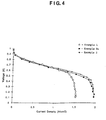
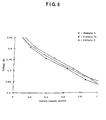
- Figures 3,4, and 5 illustrate the performance of the fuel cells referred to in Examples 1, 2, and 3.
- the invention provides an electrochemical fuel cell having a membrane electrode assembly and a flow field adjacent thereto wherein the flow field is formed of an electrically conductive porous carbon material having a porosity of at least 50 percent and a mean pore size of at least 35 micrometres wherein the porous material has a thickness of at least 20 mils (0.5mm) and is such that a 3 inch by 3 inch (7.5cm x 7.5cm) portion of the porous material can imbibe at least 0.5 gram of water per gram of material in ten seconds when held vertically in 3/16 inch (0.5cm) of water.
- the fuel cell of the invention is able to operate at relatively high current densities and relatively high voltages at lower gas flow rates.
- the membrane and the layer of polymer containing metal catalytically-active particles must be hydrated in order to be sufficiently ionically conductive.
- active layer the layer of polymer containing metal catalytically-active particles
- water is formed on the cathode side of the active layer, which condenses within the adjacent flow field. Water may also be present due to the humidification of one or both of the reactant gases.
- the efficiency of the fuel cell is reduced, since diffusion of gas through liquid water is slow relative to its diffusion through water vapor.
- the porosity and pore size characteristics of the flow field in the fuel cell of the invention are believed to improve the mass transfer capabilities, which results in higher voltages at high current densities.
- the relatively high porosity and large pores combine to preserve effective gas transport in the presence of liquid water. Because the feed gas flow is in the plane of the flow field and substantially parallel to the active layer, the liquid is swept away from the active layer and out of the flow field by the gas stream, thus keeping pores open for effective transport of reactant gas to the catalytically-active particles. However, when the flow field is relatively thick, (greater than 20 mils for air feed stoichiometry equal to 2 at 30 psig) the gas velocity becomes inadequate to keep the pores clear of water.
- annular flow a type of flow condition therein which may be referred to as annular flow, wherein the liquid spreads out onto the solid surfaces of the porous structure, leaving the centers of the large pores open and available for effective gas transport.
- the fuel cell includes a membrane electrode assembly having a solid polymer electrolyte, and at least two active layers positioned on the same side of the membrane; wherein the active layers comprise catalytically-active particles and an ionomer; the average equivalent weights of the ionomers in the layers differ by at least 50; and the active layer positioned closest to the membrane (hereafter, the "first" active layer) contains the ionomer with the lower average equivalent weight.
- the "second" active layer (the layer positioned on the side of the first active layer which is opposite to the side facing the membrane) may either be positioned adjacent to and in contact with the first active layer, or one or more additional active layers may be positioned between the first and second active layers.
- the cell further preferably has a membrane electrode assembly having a solid polymer electrolyte, and at least one active layer positioned on one side of the membrane; wherein the active layer comprises (a) catalytically-active particles, and (b) an ionomer having an equivalent weight in the range of from 650 to 950 and which is substantially insoluble in water at temperatures of less than 100°C.
- MEAs membrane electrode assemblies
- the equivalent weight of the ionomer is believed to affect the water content of the active layer. It is believed, without intending to be bound by any particular theory, that the lower equivalent weight ionomer maintains a higher water content at low current densities. This higher water content improves the proton conductivity and the accessibility of the catalytically active particles, thereby increasing the voltage. However, this increase in water content can lower the performance (voltage) at higher current densities. It has been discovered that the performance at both high and low current densities may be optimized by using a multi-layer active layer with a different equivalent weight ionomer in each layer. It is believed, without intending to be bound by any particular theory, that the improved performance results from the differences in hydrophilicity between the layers.
- the lower equivalent weight ionomer adjacent to the membrane is believed to provide an area within the MEA having a high water content, for better performance at low current densities, while the less hydrophilic higher equivalent weight ionomer helps transport water away from the membrane at higher current densities.
- the use of a relatively low equivalent weight ionomer gives better performance at lower current densities.
- the electrochemical fuel cell according to the invention preferably has a membrane electrode assembly and a layer of an electrically conductive porous material adjacent thereto which has at least two portions with different mean pore sizes, wherein a first portion of the layer adjacent to the membrane electrode assembly has a porosity no greater than a second portion of the layer adjacent to the opposite side of the layer; the second portion has a porosity of at least 82 percent; and the second portion has an mean pore size which is at least 10 microns and at least ten times greater than the mean pore size of the first portion.
- the electrochemical fuel cell preferably has a membrane electrode assembly with a nonwoven porous layer of an electrically conductive porous material adjacent thereto which has at least two portions with different mean pore sizes, wherein a first portion of the layer adjacent to the membrane electrode assembly has a porosity no greater than a second portion of the layer adjacent to the opposite side of the layer; the second portion has a porosity of at least 50 percent; and the second portion has a mean pore size which is at least 35 microns and at least ten times greater than the mean pore size of the first portion.
- the electrochemical fuel cell may be prefered has : (a) applying a layer of a conductive composition to a sheet of a porous conductive material having a porosity of at least 82 percent under conditions sufficient to form a porous, solid layer of the conductive composition on one side of the sheet of porous conductive material, forming a composite thereby, and (b) placing the composite adjacent to the membrane electrode assembly so that the side of the composite to which the conductive composition was applied is facing said assembly.
- the fuel cells according to the above preferred aspects of the invention are able to operate at a high current density at a relatively high voltage, have a relatively high power density, and provide a high power density even when operated under relatively low gas pressures.
- the membrane/electrode assembly may be prepared by the sequential steps of (i) applying a layer of the composition of the first aspect of the invention to a solid polymer electrolyte, a carbon fiber paper, or a release substrate; (ii) heating the composition under conditions sufficient to volatilize at least 95 percent of component (b); and (iii) positioning the composition in contact with the solid polymer electrolyte, if the composition was not applied directly to the solid polymer electrolyte, forming the membrane/electrode assembly thereby.
- membrane electrode assembly refers to the combination of the solid polymer electrolyte (also referred to herein as a “membrane”) and catalytically-active particles in the fuel cell assembly, regardless of its configuration or method of preparation.
- the layer of membrane material containing such particles are referred to as the "active layer”, regardless of whether such particles are incorporated into a discrete layer of polymer (2) and applied or laminated to the surface of the membrane (3), or incorporated into the membrane itself.
- the flow field (4) is a layer of an electrically conductive porous material having a gas stream inlet and outlet connected thereto.
- the flow field may comprise porous carbon material.
- the fuel cell of the first aspect of the invention preferably contains no impermeable flow field components having engraved, milled, or molded flow channels configured across its entire active face. These channels deliver gases directly to the active layerthrough a porous carbon "backing layer" which supports the active layer, as illustrated in Figures 1 and 4 of U.S. Patent 5,108,849.
- the flow field, bipolar plates, and/or end plates used as supports for the fuel cell and to separate cells in a multi-cell configuration may contain one or more ducts therein to increase the flow of reactant gases to the flow field in the fuel cell of the first aspect of the invention. An example of such ducts is illustrated in Figure 2.
- the flow field may have interdigitated channels cut into it to lower the pressure drop introduced into the reactant gases.
- the porous carbon material may be treated with a perfluorosilane or fluorine composition to increase its hydrophobicity, or oxidized, sulfonated, or coated with a hydrophilic material to increase its hydrophilicity.
- the flow field has a thickness of at least 20 mils, and a relatively high wettability.
- the wettability of the flow field may be determined experimentally by the following method: a 3 inch by 3 inch sample of the flow field is held vertically in a pan containing water of 3/16 inch depth. The amount of water imbibed in 10 seconds is measured by weighing. The flow fields material imbibes at least 0.5 g of water per gram of porous material, more preferably at least 1 g of water per gram of porous material.
- the conductivity of the flow field layer in the first aspect of the invention is preferably at least 0.01 Siemens/cm (S/cm), more preferably at least 0.1 S/cm, and most preferably at least 0.2 S/cm.
- the preferred thickness of the flow field will depend on the optimal pressure drop across the flow field, but is preferably at least 1 mil, more preferably at least 5 mils, and is most preferably at least 10 mils; but is preferably no greater than 250 mils, more preferably no greater than 100 mils, and is most preferably no greater than 50 mils.
- the porosity of the flow field is preferably at least 75 percent, more preferably at least 80 percent.
- the mean pore size of the flow field is preferably at least 45 microns, more preferably at least 50 microns; but is preferably no greater than 250 microns.
- the term "mean pore size" as used herein means that half the open volume of the material is contained in pores larger in diameter than the mean pore size, and half is contained in pores equal to or smaller than the mean pore size.
- the mean pore size may be measured by any convenient method, such as by mercury porosimetry.
- the device used to measure the mean pore size distribution of the layer may be calibrated using silica/alumina calibration standards (available from Micromeritics, Norcross, GA).
- a layer of a catalyst "ink” is first applied to a solid polymer electrolyte, a carbon fiber paper, or a release substrate.
- Catalyst inks typically comprise catalytically-active particles (such as platinum supported on carbon), binder, solvent or dispersing aid and, optionally, a plasticizing agent.
- the ink comprises catalytically-active particles, and at least one compound which functions as an ionomer, such as a polytetrafluoroethylene polymer having sulfonic acid groups and an equivalent weight (based on the acid groups) in the range of from 650 to 1400.
- the ink also preferably contains an organic solvent or dispersing aid which permits the application of a thin, uniform layer of the catalyst/ionomer mixture to the solid polymer electrolyte, carbon fiber paper, or release substrate.
- a layer of catalyst "ink” is first applied to a solid polymer electrolyte, and then a layer of a second and third ink is applied to the portion of the MEA located opposite the first active layer or to a release substrate, or on top of the first active layer.
- active layer refers to a layer comprising a mixture of ionomer and catalytically-active particles.
- the MEA may be prepared by any suitable method, but is preferably prepared by applying the catalyst ink (a suspension or dispersion of the catalytically-active particles) directly to a solid polymer electrolyte as described, for example, in U.S. Patent 5,211,984.
- the ink is applied to the membrane in one or more applications sufficient to give a desired loading of catalytically-active particles.
- the layer of catalytically-active particles is prepared by applying at least two inks in separate steps to form layers of the different inks, with the highest equivalent weight binder ink applied in such a manner so that it will be positioned adjacent to the flow field in the fuel cell.
- the membrane electrode assembly comprises a solid polymer membrane having at least two layers of catalyst ink on at least one side thereof, wherein at least two layers of the catalyst ink comprise polytetrafluoroethylene polymers having pendant sutfonic acid groups, the equivalent weights of which differ by more than 50, and wherein the layer having the highest equivalent weight is positioned adjacent to the flow field.
- the fuel cells described herein may be incorporated in a multi-cell assembly or "stack" comprising a number of fuel cells arranged in series.
- An example of a repeat unit is illustrated in Figure 2, which shows an anode flow field (5), an MEA (6), a cathode flow field (7), and a bipolar separator plate (8).
- the bipolar separator plate has ducts (9) and (10) which transport the reactants and reaction products to and from the flow field.
- the MEA is located between two porous flow fields that have an inert material impregnated into the border regions (the darker areas in the figure) in order to prevent the reactant gases from escaping to the outside.
- the material used to prepare the bipolar plate separator may be selected from a variety of rigid or nonrigid materials, and the plate has gas delivery ducts molded or embossed into its surface. These ducts deliver reactant gases to, and remove reaction products from, the porous flow fields. In an alternative embodiment, gases and products may be introduced or removed via ducts or open spaces in the porous flow field connected to manifolds.
- the bipolar separator plate may also have an internal structure for circulating a cooling fluid therein.
- the first active layer is preferably first dried sufficiently before application of the second ink to prevent too much mixing of the inks.
- a minor degree of mixing of the inks at their point of contact with each other may be desirable since it will promote electrical and ionic conductivity between the active layers.
- they are preferably heated under conditions sufficient to volatilize at least 95 percent of any organic solvent or dispersing aid present in the inks.
- solid polymer electrolyte refers to a porous layer comprised of a solid polymer which has a conductivity of at least 1 x 10 -3 Siemens/cm (S/cm) under the operating conditions of the fuel cell or electrolytic cell, or which may be reacted with acid or base to generate a porous layer having such conductivity.
- the solid polymer electrolyte comprises a film of a sulfonated fluoropolymer, or a layered composite of films of sulfonated fluoropolymers having different equivalent weights.
- the ink After application of a catalyst ink to a solid polymer electrolyte, the ink is preferably heated under conditions sufficient to remove enough of the organic solvent or dispersing aid so that the active layer comprises at least 99 percent by weight, more preferably at least 99.9 percent by weight of the mixture of catalytically-active particles and the ionomer.
- the ink is applied in an amount sufficient to provide a layer of the mixture which has a thickness of at least 1 ⁇ m, more preferably at least 5 ⁇ m, and most preferably at least 10 ⁇ m; but is preferably no greater than 30 ⁇ m.
- the porosity of the layer is preferably at least 30 percent, more preferably at least 50 percent; but is preferably no greater than 90 percent, more preferably no greater than 60 percent.
- the mean pore size of the layer is preferably at least 0.01 ⁇ m, more preferably at least 0.03 ⁇ m; but is preferably no greater than 10 ⁇ m, more preferably no greater than 0.5 ⁇ m, and is most preferably 0.1 ⁇ m.
- the thickness, porosity, and pore size characteristics referred to above refer to measurements taken when the ionomer(s) contained in the layer are in their dry and protonated form.
- the components of the MEAs are assembled by positioning one of the active layers in contact with the solid polymer electrolyte, and then positioning the second and third active layer so that it is between the first active layer and the porous carbon material, forming the membrane/electrode assembly thereby.
- catalytically-active particles refers to particles of a metal or compound which are catalytic for the electroreduction of oxygen or electrooxidation of hydrogen or methanol under the pressure and temperature conditions in the fuel cell.
- examples of such particles which are useful include particles of platinum, ruthenium, gold, palladium, rhodium, iridium, electroconductive and reduced oxides thereof, and alloys of such materials, either in combination with each other or with other transition metals.
- the particles may be supported on a suitable material, if desired, such as carbon black.
- the catalytically-active particles are platinum particles supported on carbon, which preferably contain from 10 percent to 30 percent by weight of platinum.
- the size of the catalytically-active particles is preferably at least 10 ⁇ , more preferably at least 20 ⁇ ; but is preferably no greater than 500 ⁇ , more preferably no greater than 200 ⁇ . Larger size particles may also be utilized, or may form during cell operation by the agglomeration of smaller particles. However, the use of such particles may result in decreased cell performance.
- the catalytically-active particles are preferably used in an amount sufficient to provide an optimum catalytic effect under the operating conditions of the electrochemical device in which they are employed.
- they are utilized in an amount sufficient to provide a loading level on the cathode side of the membrane of at least 0.05 mg/cm 2 , more preferably at least 0.1 mg/cm 2 , and is most preferably at least 0.15 mg/cm 2 ; but is preferably no greater than 0.45 mg/cm 2 , more preferably no greater than 0.35 mg/cm 2 , and is most preferably no greater than 0.25 mg/cm 2 .
- the loading level on the anode side of the membrane is preferably at least 0.01 mg/cm 2 , but no greater than 0.15 mg/cm 2 .
- the particles are preferably present in the ink in an amount, based on the weight of the catalytic particles, including their support, if any, sufficient to provide a weight ratio of particles:ionomer of at least 2:1, but preferably no more than 5:1.
- suitable organic compounds for use in the preparation of the catalyst ink include polar solvents such as glycerin, C 1-6 alcohols, and other compounds such as ethylene carbonate, propylene carbonate, butylene carbonate, ethylene carbamate, propylene carbamate, butylene carbamate, acetone, acetonitrile, difluorobenzene, and sulfolane, but is most preferably propylene carbonate.
- the organic compound is preferably present in an amount, based on the weight of the composition, of at least 10 percent, more preferably at least 20 percent, and is most preferably at least 30 percent; but is preferably no greater than 90 percent.
- solvents in the ink function primarily as solvents or dispersing aids.
- Suitable ionomers for use in the preparation of the catalyst inks described herein include any polymer or oligomer having an ionic conductivity of at least 1 x 10 -3 S/cm, more preferably at least 10 -1 S/cm (under the operating conditions of the fuel cell or electrolytic cell), or which may be reacted with acid or base to generate an oligomer or polymer having ionic conductivity.
- Suitable ionomers include fluoropolymers.having pendant ion exchange groups, such as sulfonic acid groups in proton or salt form. Examples of such include sulfonic fluoropolymers having fluoropolymer backbones and 1 to 5 carbon atom pendent ion exchange groups attached thereto and terminating in a sulfonyl group are suitable for use in the present invention. Examples of such sulfonic ion exchange group fluoropolymers are illustrated, for example, in U.S.
- the ionomer has a substantially fluorinated polymer backbone and a recurring pendent group having the formula: ⁇ O ⁇ (CFR) a ⁇ (CFR') b ⁇ SO 3 M wherein: a and b are independently 0 or an integer of 1 to 3; a + b is at least 1; R and R' are independently selected from halogen, perfluoroalkyl, and fluorochloroalkyl; and M is independently selected from hydrogen or an alkali metal.
- ionomers useful in forming both thick and thin composite membrane layers are characterized by a substantially fluorinated polymer backbone and a recurring pendent group having the formula: O ⁇ (CFR) a ⁇ (CFR') b ⁇ O ⁇ (CF 2 ) c ⁇ SO 3 M wherein: a and b are independently 0 or an integer of 1 to 3; c is an integer of 1 to 3; a + b is at least 1; R and R' are independently selected from perfluoroalkyl, halogen, and fluorochloroalkyl; and M is independently selected from hydrogen or an alkali metal.
- Ionomers having the above formulas are disclosed in U.S. Patents 4,478,695; 4,417,969; 4,358,545; 4,940,525; 3,282,875; and 4,329,435.
- the ionomer is preferably present in an amount, based on the weight of the composition, of at least 0.5 percent but preferably no more than 5 percent.
- the ionomer may be utilized in any ionic form, such as the proton form or salt form of the corresponding oligomer or polymer. Examples of salt forms include quaternary ammonium, sodium, lithium, and potassium.
- the ionomers used to prepare the inks preferably have an equivalent weight, based on the number of pendant ionic groups per molecule, of at least 600, more preferably at least 700, and preferably no greater than 1200, more preferably no greater than 950.
- the ionomer must also be substantially insoluble in water at temperatures below 100°C; therefore, the minimum equivalent weight for certain fluoropolymers may be higher.
- substantially insoluble in water means that the pure ionomer in the ionic form is at least 75 percent insoluble in distilled water at any concentration.
- the difference between the equivalent weight of the ionomers in at least two of the inks used to prepare the MEA is preferably at least 50, more preferably at least 100, and is most preferably at least 300; but is preferably no greater than 800, more preferably no greater than 600, and is most preferably no greater than 400.
- the ionomer used to prepare the ink preferably has an equivalent weight of at least 650, more preferably at least 700, and is most preferably at least 770; but is preferably no greater than 950, more preferably no greater than 900, and is most preferably no greater than 840.
- the equivalent weight of the ionomer may be determined by any suitable technique, such as titration with a base, as illustrated in U.S. Patent 4,940,525.
- the fuel cells preferably contain a layer of an electrically conductive porous material (hereafter, "intermediate layer”) which is adjacent to the membrane electrode assembly and has at least two portions with different mean pore sizes.
- the portion of the layer adjacent to the membrane electrode assembly (18) (hereafter, “small pore region”) has a mean pore size which is at least ten times smaller than the portion of the layer adjacent to the opposite side of the layer (19) (hereafter, "large pore region ”):
- Compositions suitable for use in the preparation of the intermediate layer include any organic or inorganic composition which can be fabricated into a solid layer having the porosity and pore size characteristics referred to above, and which also has sufficient dimensional, hydrolytic and oxidative stability under the operating conditions of the fuel cell.
- One method of preparing an intermediate layer having assymetrical pore size characteristics is to prepare such a layer from two or more materials having different mean pore sizes.
- An example of such a method is to first obtain or prepare a material having a mean pore size suitable for the large pore region (hereafter, "large pore material”), and then infiltrate and/or coat one side of the material with a composition which will reduce the porosity of a portion of the material sufficiently to obtain the smallest desired pore size, and/or form a discrete layer of the composition on the outside of the material having the desired small pore characteristics.
- the membrane and the layer of polymer containing a metal catalyst must be hydrated in order to be sufficiently ionically conductive.
- active layer the layer of polymer containing a metal catalyst
- water is formed on the cathode side of the active layer, which condenses within the adjacent flow field. Water may also be present due to the humidification of one or both of the reactant gases.
- the efficiency of the fuel cell is reduced, since diffusion of gas through liquid water is slow relative to its diffusion through water vapor.
- the small pore region of the layer reduces the accumulation of excess liquid water in or next to the active layer because it serves as a semi-permeable layer or membrane which permits the water vapor generated within the active layer or present due to the humidification of the reactant gases to pass between the active layer and the flow field, but reduces or prevents condensation of water on the active layer and reduces or prevents the liquid water present in the flow field or large pore region of the intermediate layer from passing back through the small pore region to the active layer.
- the wettability (determined by the pore size and water-solid contact angle) of the small pore region is such that for a sufficiently large fraction of the pores the displacement pressure required to force liquid water into these pores is larger than the hydraulic pressure in the flow field components under the prevailing condition of pressure and temperature in the fuel cell.
- suitable organic compositions which may be used to prepare or infiltrate the large pore material include thermoplastic or thermosetting polymeric and oligomeric materials, such as polytetrafluoroethylenes, including those which have sulfonic acid groups, (such as NationalTM, available from DuPont), poly(alkylene oxide)s, polyolefins, polycarbonates, benzocyclobutanes, perfluorocyclobutanes, polyvinyl alcohols, and polystyrene, epoxy resins, perfluoroalkyl/acrylic copolymers, polyanilines, polypyrroles, as well as mixtures thereof.
- thermoplastic or thermosetting polymeric and oligomeric materials such as polytetrafluoroethylenes, including those which have sulfonic acid groups, (such as NationalTM, available from DuPont), poly(alkylene oxide)s, polyolefins, polycarbonates, benzocyclobutanes, perfluorocyclobutanes, polyvinyl alcohol
- the composition is a polytetrafluoroethylene, perfluoroalkyl/acrylic copolymer, or a perfluorocyclobutane, and is most preferably a perfluorocyclobutane.
- suitable inorganic compositions include clays, silicates, and titanium-based compositions.
- the composition used to prepare the small pore region of the intermediate layer preferably contains polymer, carbon particles, and a suitable carrier.
- the carrier will typically infiltrate the entire large pore material, although the majority of the polymer and carbon particles will collect on or close to the surface of the side of the material to which it is applied (depending on its porosity and the size of the particles contained in the composition), thereby forming the small pore region on the side of the material to which the composition is applied.
- the regions or portions of the intermediate layer having different mean pore sizes are not necessarily discrete layers, so long as at least the first 1 micron of depth of the small pore region and at least the first 50 microns of depth of the large pore region (as measured from the surface of the layer in a direction perpendicular to the layer) has the necessary pore characteristics.
- the intermediate layer may also be prepared by applying the composition used in the preparation of the small pore region to the membrane electrode assembly, and then positioning or laminating a layer of a large pore material adjacent thereto.
- a film of the composition used in the preparation of the small pore region may be prepared separately using conventional film manufacturing techniques, and then positioned or laminated between the membrane electrode assembly and the large pore material. If the composition is applied to the MEA, it may be applied using any suitable coating technique, such as by painting or silk-screening.
- the small pore region of the intermediate layer is preferably at least as hydrophobic as the active layer.
- the composition used to prepare the small pore region is preferably a liquid-based composition which will solidify after application. If the composition which is applied is solvent-based, enough of the solvent is removed to form a solid layer of material prior to assembling the fuel cell. Such solvent may be removed either at ambient conditions or at elevated temperatures. If appropriate, the composition is heated to increase its stability and uniformity, such as by crosslinking, molecular weight advancement, or agglomerating latex particles.
- the composition used to prepare the small pore region is to be applied directly to the membrane electrode assembly, the majority of the dissolved solids contained therein (such as the polymer) are preferably hydrophilic in character, since the membrane and active layer are normally prepared from a hydrophilic composition, and application of a solution of a primarily hydrophobic dissolved solids would normally be expected to adversely affect the properties of the active layer.
- the composition used to prepare the small pore region is still preferably hydrophobic after being cured.
- Hydrophobic fillers such as carbon fibers and/or powders treated with hydrophobic compositions such as silane- and fluorine-based compositions, may be used in the compositions that are used to prepare the small pore region to give it some hydrophobic character and affect the wettability of its pores, as well as increase the porosity and mean pore size of the solidified composition.
- the weight ratio of carbon fibers or powders to the other components in the composition is preferably at least 1:1, more preferably at least 3:1; and preferably no greater than 10:1, more preferably no greater than 5:1; and is most preferably 3:1.
- the small pore region is prepared by applying the composition to a large pore material, such as a graphite paper
- a large pore material such as a graphite paper
- the relatively fine pore structure of the paper will help keep the majority of fillers in the composition close to the surface on the side of the paper to which it is applied.
- the composition may be one which is primarily hydrophilic as applied, but hydrophobic upon curing, such as a polytetrafluoroethylene latex.
- the small pore region is prepared by applying a hydrophilic composition to a large pore material, a thin coating of a highly hydrophobic material such as ZonylTM 7040, a perfluoroalkyl acrylic copolymer available from DuPont, may be applied to the side of the small pore region facing the MEA to further increase its hydrophobicity.
- a highly hydrophobic material such as FluoradTM FC 722 and FC 724, available from 3M.
- the MEA is preferably prepared by applying the catalyst ink (a suspension or dispersion of the catalyst) directly to the membrane as described, for example, in U.S. Patent 5,211,984.
- the catalyst ink a suspension or dispersion of the catalyst
- the composition used to prepare the small pore region is preferably applied first, followed by the catalyst ink, so that the infiltrated porous carbon material may be utilized as an intermediate layer, as well as a support layer for the catalyst.
- this method, as well as any methods which require the preparation of a separate film for the intermediate layer are less preferred since such films and catalyst-containing structures must typically be laminated to the membrane portion of the membrane electrode assembly in order to assemble the fuel cell.
- Such lamination processes, wherein heat and/or excessive pressure is applied to the intermediate layer may alter or damage its pore structure.
- composition of the intermediate layer may be formulated to optimize the maximum voltage at which the fuel cell will operate at a given current density. It is believed that higher voltages at higher current density require the small pore region to be more hydrophobic than at lower current densities. For example, if a higher voltage at a lower current density is desired, compositions having a higher carbon/polymer ratio (such as 5:1) are preferred for use in the preparation of the small pore region, particularly when applied to a graphite paper having a relatively low porosity. Likewise, if higher voltages at higher current densities are preferred, lower carbon/polymer ratios (such as 3:1) are preferred, particularly when applied to a graphite paper having a relatively high porosity.
- the small pore region preferably has a thickness in the range of from 1 micron to 150 microns (as measured in a direction perpendicular to the intermediate layer), and has the desired porosity and pore size characteristics. More preferably, the region has a thickness in the range of from 5 to 25 microns.
- the portion of the region adjacent to the MEA is sufficiently porous to permit the transmission of water vapor through the region.
- the porosity of this portion of the region is preferably at least 10 percent.
- the mean pore size of the small pore region is preferably at least 0.1 micron, more preferably at least 1 micron; but is preferably no greater than 10 microns.
- the mean pore size may be measured by any convenient method, such as by mercury porosimetry.
- the device used to measure the mean pore size distribution of the layer may be calibrated using silicalalumina calibration standards (available from Micromertrics, Norcross, GA).
- mean pore size means that half the open volume of the material is contained in pores larger in diameter than the mean pore size, and half is contained in pores equal to or smaller than the mean pore size.
- the porosity of the small pore region is preferably at least 10 percent.
- Conductive fillers and non-conductive inert or fugitive fillers may be incorporated into the composition to achieve the desired pore structure.
- Intrinsically conductive polymers such as doped polyaniline or polypyrrole may also be used to prepare the composition in order to increase its conductivity.
- the pore structure of the small pore region may also be controlled to some extent by the selection of the polymer or the use of an oligomeric composition.
- the large pore region preferably has a thickness of at least 2 mils, more preferably at least 6 mils; but is preferably no greater than 50 mils.
- the porosity of this region is preferably at least 82 percent, more preferably at least 85 percent, and most preferably at least 87.5 percent.
- the mean pore size of the large pore region is preferably at least 30 microns. The porosity and pore size values given above represent the characteristics of the small pore region for at least the first micron of its depth from the side of the intermediate layer next to the MEA and at least the first 50 microns of its depth from the opposite side of the intermediate layer, regardless of its method of preparation.
- the porous carbon material may be treated with a perfluorosilane or fluorine composition to increase its hydrophobicity, or oxidized, sulfonated, or coated with a hydrophilic material to increase its hydrophilicity. If a porous carbon material is utilized as both the flow field and the large pore material may have interdigitated channels cut into it to lower the pressure drop introduced into the reactant gases.
- the conductivity of the intermediate layer is preferably at least 0.01 Siemens/cm (S/cm), more preferably at least 0.1 S/cm, and most preferably at least 10 S/cm.
- the conductivity of the layer may be increased by the addition of conductive fillers, such as carbon fibers or particles, or by the incorporation of conductive salts or polymers.
- catalytically-active particles refers to particles of a metal or compound which is catalytic for the electroreduction of oxygen or electrooxidation of hydrogen or methanol under the pressure and temperature conditions in the fuel cell.
- examples of such particles which are useful include particles of platinum, ruthenium, gold, palladium, rhodium, iridium, electroconductive and reduced oxides thereof, and alloys of such materials, either in combination with each other or with other transition metals.
- the particles may be supported on a suitable material, if desired, such as carbon black.
- the catalytically-active particles are platinum particles supported on carbon, which preferably contain from 10 percent to 30 percent by weight of platinum.
- the size of the catalyst particles is preferably at least 10 ⁇ , more preferably at least 20 ⁇ ; but is preferably no greater than 500 ⁇ , more preferably no greater than 200 ⁇ .
- the particles are preferably used in an amount sufficient to provide an optimum catalytic effect under the operating conditions of the electrochemical device in which they are employed. Relative to the amount of binder, however, the particles are preferably present in the ink in an amount, based on the weight of the catalytic particle, including its support, if any, sufficient to provide a weight ratio of component (a):component (c) of at least 2:1, but preferably no more than 5:1.
- Suitable organic compounds include organic compounds having a pKa (the negative logarithm (to the base 10) of the equilibrium constant, K, for the reaction between the compound and water) of at least 18 and a basicity parameter, ⁇ , of less than 0.66.
- the pKa is at least 25.
- ⁇ is less than 0.48, and is more preferably less than 0.40.
- the basicity parameter for a number of organic compounds, as well as reference procedures for its determination, are described in Kamlet et al., "Linear Solvation Energy Relationships. 23. A Comprehensive Collection of the Solvochromatic Parameters, n*, ⁇ , and ⁇ , and Some Methods for Simplifying the Generalized Solvatochromic Equation," J. Org. Chem. , Vol. 48, pp. 2877-2887 (1983).
- the compound volatilizes at temperatures in the range of from 100°C to 250°C without significant degradation which can impair the performance of the active layer.
- a relatively low volatization temperature is also preferred, since organic compounds (component (b)) that are not removed from the layer can add to the electrical resistance of the layer, causing poorer MEA performance.
- This characteristic is particularly important when the binder is utilized in its proton form, since the binder will act as a catalyst to further promote the degradation of any residual organic compound.
- the use of a proton form of the binder has advantages, however, since quaternary ammonium cations present in an ink composition are difficult to remove and may contribute to a long "break in" period when a fuel cell or fuel cell stack is initially started.
- the boiling point of the solvent is greater than 100°C so that, upon curing of the ink, the water or low boiling solvents which may be present in the ink (typically introduced to the ink by way of a commercially available binder containing such components) are removed first.
- suitable organic compounds for use as component (b) include ethylene carbonate, propylene carbonate, butylene carbonate, ethylene carbamate, propylene carbamate, and butylene carbamate, acetone, acetonitrite, difluorobenzene, and sulfolane, but is most preferably propylene carbonate.
- the organic compound is preferably present in an amount, based on the weight of the composition, of at least 10 percent, more preferably at least 20 percent, and is most preferably at least 30 percent; but is preferably no greater than 90 percent.
- Suitable polymeric binders for use in the preparation of the composition of the invention include any polymer or oligomer having ionic conductivity of at least 1x10 -3 S/cm, more preferably at least 10 -1 S/cm (under the operating conditions of the fuel cell) or electrolytic cell, or which may be reacted with acid or base to generate an oligomer or polymer having ionic conductivity. If the binder has pendant ionic groups, it preferably has an equivalent weight of at least 600, more preferably at least 700, and preferably no greater than 1200, more preferably no greater than 950.
- the equivalent weight of the binder is based on the number of pendant ionic groups per molecule, as may be determined by any suitable technique, such as titration with a base, as illustrated in U.S. Patent 4,940,525.
- suitable binders include perfluorinated polymers and polytetrafluoroethylene polymers, and polytetrafluoroethylene polymers having pendant sulfonic acid groups, (such as NafionTM, available from DuPont).
- the binder is preferably present in an amount, based on the weight of the composition, of at least 0.5 percent but preferably no more than 5 percent.
- One advantage of the present invention is that the ionomer may be utilized in any ionic form, such as the proton form or salt form of the oligomer or polymer. Examples of salt forms include quaternary ammonium, sodium, lithium, and potassium.
- the MEA may be prepared by any suitable technique.
- the MEA is prepared by applying one or more layers of the catalyst ink (the composition of the invention) directly to the solid polymer electrolyte as described, for example, in U.S. Patent 5,211,984.
- the term "solid polymer electrolyte” as used herein refers to a membrane comprised of a solid polymer which has a conductivity of at least 1x10 -3 S/cm under the operating conditions of the fuel cell or electrolytic cell, or which may be reacted with acid or base to generate a membrane having such conductivity.
- the solid polymer electrolyte comprises a film of a sulfonated fluoropolymer.
- Another method comprises applying one or more layers of the catalyst ink to a release material, such as a polytetrafluoroethylene-coated substrate, curing the ink, and then laminating the cured material to the membrane.
- a third method comprises applying one or more layers of the catalyst ink to one side of a sheet of porous carbon material, such as a carbon or graphite paper, and then placing the side of the material to which the ink was applied adjacent to the membrane. If the ink is cured before being placed next to the membrane, it should then preferably be laminated to the membrane to ensure good contact between the two.
- the ink may be cured using any suitable method for removing at least 95 percent of component (b), as well as any other volatile organic solvents contained in the ink, such as by heating at an elevated temperature optionally under reduced pressure.
- the ink is heated to a temperature at which the component (b) is volatile, but below its boiling point.
- the inks preferably contain a polytetrafluoroethylene polymer having pendant sulfonic acid groups as the binder, and the layer of ink closest to the membrane has an equivalent weight which differs from the equivalent weight of the binder in the ink layer adjacent thereto by at least 50.
- the layer having the lowest equivalent weight binder is preferably positioned adjacent to the solid polymer electrolyte.
- the ink is heated under conditions sufficient to remove at least 99 percent, more preferably at least 99.9 percent of component (b).
- the ink is applied in an amount sufficient to provide a layer of the composition which, when dry and protonated, has a thickness of at least 1 ⁇ m, more preferably at least 5 ⁇ m, and most preferably at least 10 ⁇ m; but is preferably no greater than 30 ⁇ m.
- the porosity of the layer is preferably at least 30 percent, more preferably at least 50 percent; but is preferably no greater than 90 percent, more preferably no greater than 60 percent.
- the mean pore side of the layer is preferably at least 0.01 ⁇ m, more preferably at least 0.03 ⁇ m; but is preferably no greater than 10 ⁇ m, more preferably no greater than 0.5 ⁇ m, and is most preferably 0.1 ⁇ m.
- Membrane and electrode structures were prepared as follows: An ion exchange membrane prepared from perfluorosulfonic acid ionomer having an equivalent weight of 800, a thickness of 2.4 mil (60 ⁇ m) dried and 5 mil (127 ⁇ m) fully hydrated (available from The Dow Chemical Company as XUS 13204.20) was obtained and cut into sheets 11 cm by 11 cm and placed into a NaOH bath to convert it to the Na + form.
- the electrode ink was prepared by mixing 1.08 g of a 5.79 weight percent solution of the above ionomer (in a 50:50 volume percent ethanol/water solution), 0.1875 g of 20 weight percent platinum on carbon (available from E-TEK (Natick, MA)) and 0.114 g of a 1 M solution of tetrabutylammonium hydroxide (TBAOH, a plasticizing agent) in methanol, and 0.6 g of propylene carbonate (dispersing aid). The mixture was agitated with a stir bar overnight or until the mixture was uniformly dispersed. An additional 1.2 g of propylene carbonate was then added to the mixture.
- TSAOH tetrabutylammonium hydroxide
- the catalyst ink was painted onto clean, 9 cm 2 polytetrafluoroethylene-coated fiberglass blanks (CHR Industries, New Haven, CT) which had been dried in a oven at 110°C and pre-weighed.
- the blanks were painted twice with the catalyst ink, which was completely dried before the application of the second layer.
- Pt loadings were 0.14 mg/cm 2 on the anode and 0.25 mg/cm 2 on the cathode.
- the MEA was formed by aligning a coated blank on each side of the ionomer membrane which had been dried on a vacuum table. The blanks and membrane were placed between two pieces of stainless steel to hold them while they were placed into the press.
- the assembly was placed into a press at 195°C and pressed at a pressure of 100 pounds per cm 2 of blank for 5 minutes.
- the press package was allowed to cool to room temperature before opening.
- the blank was peeled away from the layer containing catalytically-active particles, leaving the film adhered to the surface of the membrane.
- the cathode flow field was carbon paper having a porosity of 90 percent and a thickness of 24 mils (available as SpectracarbTM paper from Spectracorp (Lawrence, MA)).
- the wettability of the paper was increased by oxidation in a medium comprising 0.006M silver sulfate, 0.2M sodium persulfate, and 0.5M sulfuric acid, at a temperature of 60°C for 1 hour.
- a 3 by 3-inch sample of the paper oxidized in this manner imbibed 2.7 g of water per gram of carbon, when held vertically in a pan containing water of 3/16 inch depth for 10 seconds.
- the anode flow field was carbon paper having a porosity of 79 percent and a thickness of 14 mils.
- the membrane electrode assembly and porous flow fields were tested in a test fuel cell prepared by Fuel Cell Technologies, Inc. (Santa Fe, NM).
- the MEA and flow fields were placed between two solid graphite blocks, each with a single gas delivery channel and a single exit channel.
- the cell was placed onto a single cell test stand made by Fuel Cell Technologies, Inc.
- the performance of the flow field was illustrated in Figures 4 and 5, under the flow conditions set forth in Table I. Air was used as the oxidant gas unless as otherwise noted in the Table I.
- An MEA/electrode structure was prepared using the procedure described in Example 1, except that the electrode ink was prepared by mixing 1 g of a 5 percent solution of NationalTM (an 1100 equivalent-weight polytetrafluoroethylene having sulfonic acid groups, available from DuPont), 0.130 g of carbon-supported platinum containing 20 percent by weight of platinum, and 0.076 g of a 1 M solution of tetrabutylammonium hydroxide (TBAOH) in methanol, and 1.2 g of propylene carbonate (a dispersing aid).
- TSAOH tetrabutylammonium hydroxide
- propylene carbonate a dispersing aid
- Example 2d A performance curve obtained using pure oxygen as the gas feed is shown in Figure 3 as Example 2d.
- An MEA/electrode structure was prepared using the procedure described in Example 1, except that two electrode inks as described in Examples 1 and 2 were prepared separately.
- the ink of Example 2 was painted onto the fiberglass blank to be used with the cathode side of the membrane, and allowed to dry completely, followed by an application of the ink described in Example 1.
- the ink described in Example 1 was applied to the fiberglass blank to be used with the anode side of the membrane.
- Platinum loadings were 0.14 mg/cm 2 on the anode side of the membrane and 0.25 mg/cm 2 on the cathode side of the membrane.
- a fuel cell was assembled and tested as described in Example 1. The performance of the fuel cell was illustrated in Figures 4 and 5, under the flow conditions set forth in Table I.
Landscapes
- Chemical & Material Sciences (AREA)
- Chemical Kinetics & Catalysis (AREA)
- Electrochemistry (AREA)
- General Chemical & Material Sciences (AREA)
- Engineering & Computer Science (AREA)
- Manufacturing & Machinery (AREA)
- Life Sciences & Earth Sciences (AREA)
- Sustainable Development (AREA)
- Sustainable Energy (AREA)
- Composite Materials (AREA)
- Materials Engineering (AREA)
- Inert Electrodes (AREA)
- Fuel Cell (AREA)
- Coating Of Shaped Articles Made Of Macromolecular Substances (AREA)
- Compositions Of Macromolecular Compounds (AREA)
Abstract
Description
| Example # | Oxidant Humidifier Temperature (°C) | Inlet Pressure (psig) | Outlet Pressure (psig) | Pressure Drop (psi) | Oxidant Stoichiometry at 2 |
| 1 | 85 | 32.7 | 31.0 | 1.7 | 1.0 |
| 2a | 90 | 32.9 | 31.0 | 1.9 | 1.0 |
| 2b | 90 | 31.9 | 30.0 | 1.9 | 1.5 |
| 2c | 90 | 32.9 | 30.0 | 2.9 | 2.0 |
| 2d | 90 | 33.0 | 31.5 | 1.5 | 2.4 |
| 3 | 85 | 32.3 | 31.0 | 1.3 | 1.0 |
Claims (10)
- An electrochemical fuel cell having a membrane electrode assembly and a flow field adjacent thereto wherein the flow field is formed of an electrically conductive porous carbon material having a porosity of at least 50 percent, and a mean pore size of at least 35 micrometres wherein the porous material has a thickness of at least 20 mils (0.5mm) and is such that a 3 inch by 3 inch (7.5cm x 7.5cm) portion of the porous material can imbibe at least 0.5 gram of water per gram of material in ten seconds when held vertically in 3/16 inch (0.5cm) of water.
- The fuel cell of Claim 1 wherein the porous material is such that a 3 inch by 3 inch (7.5cm x 7.5cm) portion can imbibe at least 1 gram of water per gram of material in ten seconds when held vertically in 3/16 inch (0.5cm) of water.
- The fuel cell of Claim 1 wherein the flow field has a porosity of at least 75 percent.
- The fuel cell of Claim 1 wherein the flow field has a porosity of at least 80 percent
- The fuel cell of Claim 1 wherein the flow field has a mean pore size of at least 45 micrometres.
- The fuel cell of Claim 1 wherein the flow field has a mean pore size of at least 50 micrometers.
- The fuel cell of Claim 1 wherein the flow field has a mean pore size of no greater than 250 micrometres.
- The fuel cell of Claim 1 wherein the membrane electrode assembly comprises a solid polymer membrane having at least two layers of catalytically-active particles ink on at least one side thereof, wherein at least two layers of the catalytically-active particles ink comprise polytetrafluroethylene polymers having pendant sulfonic acid groups, equivalent weights which differ by more than 50, and wherein the layer having the highest equivalent weight is positioned adjacent to the flow field.
- The fuel cell of Claim 8 wherein the porous material has a porosity of at least 80 percent and a mean pore size of at least 50 micrometres.
- A stack assembly comprising at least 3 of the fuel cells as claimed in any one of the preceding claims arranged in series, wherein each fuel cell in the series comprises, in sequence, flow field, membrane electrode assembly, flow field, and a separator plate.
Priority Applications (2)
| Application Number | Priority Date | Filing Date | Title |
|---|---|---|---|
| EP02020838A EP1267436A2 (en) | 1995-10-06 | 1996-10-04 | Membrane electrode assemblies for fuel cells |
| EP02020839A EP1267433A2 (en) | 1995-10-06 | 1996-10-04 | Flow field structures for membrane electrode assemblies of fuel cells |
Applications Claiming Priority (7)
| Application Number | Priority Date | Filing Date | Title |
|---|---|---|---|
| US54010595A | 1995-10-06 | 1995-10-06 | |
| US540105 | 1995-10-06 | ||
| US554066 | 1995-11-06 | ||
| US08/554,066 US5702755A (en) | 1995-11-06 | 1995-11-06 | Process for preparing a membrane/electrode assembly |
| US1305096P | 1996-03-08 | 1996-03-08 | |
| US13050P | 1996-03-08 | ||
| PCT/US1996/015893 WO1997013287A2 (en) | 1995-10-06 | 1996-10-04 | Flow field structures for membrane electrode assemblies of fuel cells |
Related Child Applications (4)
| Application Number | Title | Priority Date | Filing Date |
|---|---|---|---|
| EP02020838A Division EP1267436A2 (en) | 1995-10-06 | 1996-10-04 | Membrane electrode assemblies for fuel cells |
| EP02020839A Division EP1267433A2 (en) | 1995-10-06 | 1996-10-04 | Flow field structures for membrane electrode assemblies of fuel cells |
| EP02020838.5 Division-Into | 2002-09-18 | ||
| EP02020839.3 Division-Into | 2002-09-18 |
Publications (2)
| Publication Number | Publication Date |
|---|---|
| EP0853824A2 EP0853824A2 (en) | 1998-07-22 |
| EP0853824B1 true EP0853824B1 (en) | 2003-07-23 |
Family
ID=27359763
Family Applications (1)
| Application Number | Title | Priority Date | Filing Date |
|---|---|---|---|
| EP96936178A Expired - Lifetime EP0853824B1 (en) | 1995-10-06 | 1996-10-04 | Flow field structures for membrane electrode assemblies of fuel cells |
Country Status (10)
| Country | Link |
|---|---|
| EP (1) | EP0853824B1 (en) |
| JP (4) | JP3558134B2 (en) |
| KR (1) | KR19990064016A (en) |
| CN (1) | CN1201554A (en) |
| AT (1) | ATE245852T1 (en) |
| AU (1) | AU713035B2 (en) |
| CA (1) | CA2233575A1 (en) |
| DE (1) | DE69629201D1 (en) |
| RU (1) | RU2182737C2 (en) |
| WO (1) | WO1997013287A2 (en) |
Families Citing this family (80)
| Publication number | Priority date | Publication date | Assignee | Title |
|---|---|---|---|---|
| US5702755A (en) * | 1995-11-06 | 1997-12-30 | The Dow Chemical Company | Process for preparing a membrane/electrode assembly |
| JP3755840B2 (en) * | 1996-03-11 | 2006-03-15 | 田中貴金属工業株式会社 | Electrode for polymer electrolyte fuel cell |
| DE19611510A1 (en) * | 1996-03-23 | 1997-09-25 | Degussa | Gas diffusion electrode for membrane fuel cells and process for their manufacture |
| JP3773325B2 (en) * | 1997-03-17 | 2006-05-10 | ジャパンゴアテックス株式会社 | Gas diffusion layer material for polymer electrolyte fuel cell and its joined body |
| JP3714766B2 (en) * | 1997-04-04 | 2005-11-09 | 旭化成ケミカルズ株式会社 | Electrode and membrane / electrode assembly for polymer electrolyte fuel cell |
| AU727997B2 (en) * | 1997-04-07 | 2001-01-04 | Dow Chemical Company, The | Electrolysis of alkali metal halide brines using oxygen cathode systems |
| US5976726A (en) * | 1997-05-01 | 1999-11-02 | Ballard Power Systems Inc. | Electrochemical cell with fluid distribution layer having integral sealing capability |
| FR2764443B1 (en) * | 1997-06-10 | 1999-09-03 | Peugeot | FUEL CELL OF THE TYPE WITH PLATE-SHAPED REAGENT DISPENSERS |
| US5910378A (en) * | 1997-10-10 | 1999-06-08 | Minnesota Mining And Manufacturing Company | Membrane electrode assemblies |
| DE19812592B4 (en) * | 1998-03-23 | 2004-05-13 | Umicore Ag & Co.Kg | Membrane electrode unit for polymer electrolyte fuel cells, process for their production and ink |
| JP4023903B2 (en) * | 1998-04-02 | 2007-12-19 | 旭化成ケミカルズ株式会社 | Membrane / electrode assembly for polymer electrolyte fuel cells |
| US6103413A (en) * | 1998-05-21 | 2000-08-15 | The Dow Chemical Company | Bipolar plates for electrochemical cells |
| US6660424B1 (en) * | 1998-08-20 | 2003-12-09 | Matsushita Electric Industrial Co., Ltd. | Fuel cell and method of manufacture thereof |
| DE19840517A1 (en) | 1998-09-04 | 2000-03-16 | Manhattan Scientifics Inc | Gas diffusion structure perpendicular to the membrane of polymer electrolyte membrane fuel cells |
| JP4742395B2 (en) * | 1999-08-03 | 2011-08-10 | 株式会社エクォス・リサーチ | Air electrode for fuel cell |
| JP2001102059A (en) * | 1999-10-01 | 2001-04-13 | Toshiba Corp | Polymer electrolyte fuel cell system |
| JP3465656B2 (en) * | 2000-01-12 | 2003-11-10 | トヨタ自動車株式会社 | Bonded body manufacturing apparatus and bonded body manufacturing method |
| US6770394B2 (en) * | 2000-02-11 | 2004-08-03 | The Texas A&M University System | Fuel cell with monolithic flow field-bipolar plate assembly and method for making and cooling a fuel cell stack |
| WO2001059862A2 (en) * | 2000-02-11 | 2001-08-16 | The Texas A & M University System | Electroconductive fuel cell component with directly bonded layers and method for making same |
| US6828054B2 (en) | 2000-02-11 | 2004-12-07 | The Texas A&M University System | Electronically conducting fuel cell component with directly bonded layers and method for making the same |
| DK1150369T3 (en) | 2000-04-28 | 2003-10-13 | Omg Ag & Co Kg | Gas distribution structures and gas diffusion electrodes for polymer electrolyte fuel cells |
| JP3594533B2 (en) * | 2000-05-30 | 2004-12-02 | 三洋電機株式会社 | Fuel cell |
| FR2810794A1 (en) * | 2000-06-26 | 2001-12-28 | Sorapec | ASSOCIATION OF ELECTRODES AND MEMBRANE COMPRISING PROTONIC CONDUCTORS |
| JP2002015743A (en) * | 2000-06-30 | 2002-01-18 | Asahi Glass Co Ltd | Polymer electrolyte fuel cell |
| DE10042744A1 (en) * | 2000-08-31 | 2002-03-28 | Omg Ag & Co Kg | PEM fuel cell stack |
| WO2002027846A2 (en) * | 2000-09-27 | 2002-04-04 | Proton Energy Systems, Inc. | Method and apparatus for improved fluid flow within an electrochemical cell |
| JP2002313359A (en) * | 2001-04-17 | 2002-10-25 | Mitsubishi Heavy Ind Ltd | Polymer electrolyte fuel cell |
| KR100912157B1 (en) | 2001-07-18 | 2009-08-14 | 텔-아비브 유니버시티 퓨처 테크놀로지 디벨롭먼트 엘.피. | Fuel cell with proton conductive membrane and improved water and fuel handling |
| KR100407793B1 (en) * | 2001-09-04 | 2003-12-01 | 한국과학기술연구원 | proton exchange composite membranes and composite solutions having selectivity, its preparation and fuel cell comprising the same |
| US6465041B1 (en) * | 2001-12-19 | 2002-10-15 | 3M Innovative Properties Company | Method of making gas diffusion layers for electrochemical cells |
| JP2003242989A (en) * | 2002-02-13 | 2003-08-29 | Hitachi Maxell Ltd | Fuel cell |
| GB2390738B (en) * | 2002-07-09 | 2005-05-11 | Intelligent Energy Ltd | Fuel cell direct water injection |
| JP4396091B2 (en) * | 2002-09-30 | 2010-01-13 | 三菱マテリアル株式会社 | Gas diffusion layer for fuel cells |
| RU2316850C2 (en) * | 2002-10-21 | 2008-02-10 | Идеа Лаб С.Р.Л. | Platinum-free electrocatalytic materials |
| JP4647902B2 (en) * | 2002-11-29 | 2011-03-09 | 本田技研工業株式会社 | Method for manufacturing membrane-electrode structure |
| US20040151960A1 (en) * | 2003-01-31 | 2004-08-05 | Rock Jeffrey Allan | Flow restrictors in fuel cell flow-field |
| KR100647581B1 (en) | 2003-07-02 | 2006-11-24 | 삼성에스디아이 주식회사 | Microporous thin film composed of nanoparticles and its manufacturing method |
| US20050026012A1 (en) * | 2003-07-28 | 2005-02-03 | O'hara Jeanette E. | Diffusion media tailored to account for variations in operating humidity and devices incorporating the same |
| KR100729974B1 (en) * | 2003-07-31 | 2007-06-20 | 도요다 지도샤 가부시끼가이샤 | Fuel cell stack, fuel cell system, and method for producing fuel cell stack |
| JP4870328B2 (en) * | 2003-10-10 | 2012-02-08 | ペルメレック電極株式会社 | Method for manufacturing membrane-electrode assembly |
| US7655340B2 (en) * | 2004-01-16 | 2010-02-02 | Gm Global Technology Operations, Inc. | Ultra short high pressure gradient flow path flow field |
| US20050202306A1 (en) | 2004-03-11 | 2005-09-15 | Celgard Inc. | Direct methanol fuel cell |
| RU2329571C1 (en) * | 2004-04-19 | 2008-07-20 | ЭлДжи ЭЛЕКТРОНИКС ИНК. | Fuel component |
| JP5044920B2 (en) | 2004-11-25 | 2012-10-10 | 日産自動車株式会社 | Polymer electrolyte fuel cell |
| GB2422716B (en) * | 2005-01-26 | 2007-08-22 | Intelligent Energy Ltd | Multi-layer fuel cell diffuser |
| JP4715842B2 (en) * | 2005-02-21 | 2011-07-06 | 日産自動車株式会社 | Electrocatalyst production method, membrane electrode assembly production method, and polymer electrolyte fuel cell production method |
| JP4237156B2 (en) | 2005-03-28 | 2009-03-11 | 富士通株式会社 | Electrolyte composition, solid electrolyte membrane, polymer electrolyte fuel cell, and method for producing solid electrolyte membrane |
| JP2007073337A (en) * | 2005-09-07 | 2007-03-22 | Gs Yuasa Corporation:Kk | Film/electrode assembly for direct methanol type fuel cell, and direct methanol type fuel cell using the same |
| GB0519807D0 (en) * | 2005-09-28 | 2005-11-09 | Welding Inst | Fuel cell assembly |
| JP2007103083A (en) * | 2005-09-30 | 2007-04-19 | Dainippon Printing Co Ltd | Catalyst sheet for fuel cell-electrolyte membrane laminate transfer sheet and catalyst layer-electrolyte membrane laminate |
| JPWO2007069404A1 (en) * | 2005-12-16 | 2009-05-21 | 株式会社エクォス・リサーチ | Fuel cell electrode, fuel cell and fuel cell stack |
| HUP0501201A2 (en) * | 2005-12-23 | 2007-07-30 | Cella H | Electrode for electrochemical cell working with high differential pressure difference, method for producing said electrode and electrochemical cell for using said electrode |
| JP4612569B2 (en) | 2006-03-20 | 2011-01-12 | 本田技研工業株式会社 | Membrane electrode structure for polymer electrolyte fuel cell |
| US9401523B2 (en) | 2007-01-09 | 2016-07-26 | GM Global Technology Operations LLC | Fuel cell and method for reducing electrode degradation during startup and shutdown cycles |
| JP2008277093A (en) * | 2007-04-27 | 2008-11-13 | Equos Research Co Ltd | Diffusion layer for fuel cell, fuel cell, and method for producing fuel cell. |
| DE102007034967A1 (en) | 2007-07-26 | 2009-01-29 | Plansee Se | Fuel cell and process for its production |
| EP2031681A1 (en) * | 2007-08-31 | 2009-03-04 | The Technical University of Denmark | Horizontally graded structures for electrochemical and electronic devices |
| EP2062933A1 (en) | 2007-11-26 | 2009-05-27 | Solvay Solexis S.p.A. | Fluoroionomer liquid composition |
| EP2374180A1 (en) * | 2008-12-22 | 2011-10-12 | 3M Innovative Properties Company | Fuel cell membrane electrode assembly with multilayer cathode |
| KR101045207B1 (en) * | 2009-01-16 | 2011-06-30 | 삼성전자주식회사 | Fuel cell stack |
| KR101040428B1 (en) | 2009-06-09 | 2011-06-09 | 주식회사 협진아이엔씨 | Gas diffusion layer carbon substrate with double structure of polymer fuel cell membrane electrode assembly and its manufacturing method |
| JP2011014340A (en) * | 2009-07-01 | 2011-01-20 | Hitachi Ltd | Polymer membrane electrode assembly for fuel cell, and fuel cell using the same |
| KR101481187B1 (en) * | 2009-12-03 | 2015-01-09 | 현대자동차주식회사 | Gas diffusion layer for fuel cell and manufacturing method thereof |
| US8735023B2 (en) * | 2009-12-14 | 2014-05-27 | GM Global Technology Operations LLC | Fuel cell with layered electrode |
| KR101282620B1 (en) * | 2010-12-03 | 2013-07-12 | 기아자동차주식회사 | Fuel Cell Stack with Enhanced Freeze/Thaw Durability and method of manufacturing same |
| EP2684239B1 (en) | 2011-03-11 | 2025-01-01 | Audi AG | Unitized electrode assembly with high equivalent weight ionomer |
| KR101405721B1 (en) | 2011-04-29 | 2014-06-13 | 한국과학기술연구원 | A porous media with enhanced hydrophobicity and a fabrication method thereof |
| EP2729979B1 (en) * | 2011-07-08 | 2017-12-13 | Audi AG | Low platinum load electrode |
| JP5900995B2 (en) | 2012-01-20 | 2016-04-06 | アウディ アクチェンゲゼルシャフトAudi Ag | Fuel cell electrode having a gradient catalyst structure |
| US9040209B2 (en) * | 2012-02-02 | 2015-05-26 | GM Global Technology Operations LLC | Multi-layer polyelectrolyte membranes |
| JP5673655B2 (en) * | 2012-11-19 | 2015-02-18 | トヨタ自動車株式会社 | Method for producing porous layer member, and method for producing membrane electrode gas diffusion layer assembly including porous layer member |
| GB201220825D0 (en) * | 2012-11-20 | 2013-01-02 | Univ Leeds | Proton exchange membrane fuel cell |
| CN105637690B (en) | 2012-12-21 | 2018-06-22 | 奥迪股份公司 | The method for preparing electrolyte |
| JP6165878B2 (en) | 2012-12-21 | 2017-07-19 | アウディ アクチェンゲゼルシャフトAudi Ag | Electrolyte membrane, dispersion, and dispersion method |
| KR102018941B1 (en) | 2012-12-21 | 2019-09-05 | 도요타지도샤가부시키가이샤 | Proton exchange material and method therefor |
| WO2016199805A1 (en) * | 2015-06-08 | 2016-12-15 | 富士フイルム株式会社 | Solid electrolyte composition, electrode sheet for all-solid-state secondary batteries, all-solid-state secondary battery, method for producing electrode sheet for all-solid-state secondary batteries, and method for producing all-solid-state secondary battery |
| CN106935885B (en) * | 2017-03-10 | 2020-04-07 | 中国科学院青岛生物能源与过程研究所 | High-porosity porous carbon filled fuel cell flow field structure and preparation method thereof |
| WO2019046724A1 (en) | 2017-09-01 | 2019-03-07 | Itn Energy Systems, Inc. | Segmented frames for redox flow batteries |
| CN113394424B (en) * | 2021-06-11 | 2023-06-20 | 上海交通大学 | Adhesive conductive plate and its preparation method |
| JP7752598B2 (en) * | 2022-12-27 | 2025-10-10 | 三菱重工業株式会社 | Membrane electrode assembly and method for manufacturing membrane electrode assembly |
Family Cites Families (24)
| Publication number | Priority date | Publication date | Assignee | Title |
|---|---|---|---|---|
| US4215183A (en) * | 1979-01-02 | 1980-07-29 | General Electric Company | Wet proofed conductive current collector for the electrochemical cells |
| BR8202395A (en) * | 1981-05-01 | 1983-04-12 | Du Pont | MEMBRANE COMPOSITE SET / ELECTROCHEM CELL ELECTRODE AND ELECTROLYSIS PROCESS |
| US4469579A (en) * | 1981-06-26 | 1984-09-04 | Diamond Shamrock Corporation | Solid polymer electrolytes and electrode bonded with hydrophylic fluorocopolymers |
| JPS58155663A (en) * | 1982-03-12 | 1983-09-16 | Hitachi Ltd | Fuel cell |
| JPS6152383A (en) * | 1984-08-21 | 1986-03-15 | Japan Storage Battery Co Ltd | Electrochemical device using cation exchange membrane as electrolyte |
| JPH07118324B2 (en) * | 1985-08-30 | 1995-12-18 | 株式会社東芝 | Method for manufacturing gas diffusion electrode |
| JPS6280965A (en) * | 1985-10-02 | 1987-04-14 | Hitachi Ltd | Fuel cell |
| US5171644A (en) * | 1991-01-09 | 1992-12-15 | The Dow Chemical Company | Electrochemical cell electrode |
| JP3245929B2 (en) * | 1992-03-09 | 2002-01-15 | 株式会社日立製作所 | Fuel cell and its application device |
| GB9213124D0 (en) * | 1992-06-20 | 1992-08-05 | Johnson Matthey Plc | High performance electrode |
| US5292600A (en) * | 1992-08-13 | 1994-03-08 | H-Power Corp. | Hydrogen power cell |
| JP3356465B2 (en) * | 1992-09-18 | 2002-12-16 | 株式会社東芝 | Method for manufacturing electrode for solid polymer electrolyte fuel cell |
| JPH06203840A (en) * | 1993-01-08 | 1994-07-22 | Asahi Chem Ind Co Ltd | Solid polyelectrolyte fuel cell |
| JP3892053B2 (en) * | 1993-03-26 | 2007-03-14 | 旭化成ケミカルズ株式会社 | Proton exchange membrane fuel cell |
| US5415888A (en) * | 1993-04-26 | 1995-05-16 | E. I. Du Pont De Nemours And Company | Method of imprinting catalytically active particles on membrane |
| IT1270878B (en) * | 1993-04-30 | 1997-05-13 | Permelec Spa Nora | IMPROVED ELECTROCHEMISTRY CELL USING ION EXCHANGE MEMBRANES AND METAL BIPOLAR PLATES |
| JPH07135004A (en) * | 1993-11-12 | 1995-05-23 | Toyota Motor Corp | Solid polymer electrolyte membrane and fuel cell |
| BE1008455A3 (en) * | 1994-06-07 | 1996-05-07 | Vito | ELECTRODE GAS DIFFUSION WITH CATALYST FOR AN ELECTROCHEMICAL CELL WITH SOLID ELECTROLYTE AND METHOD FOR MANUFACTURING SUCH ELECTRODE. |
| JPH0888007A (en) * | 1994-09-16 | 1996-04-02 | Matsushita Electric Ind Co Ltd | Polymer electrolyte fuel cell and its electrode |
| US5863671A (en) * | 1994-10-12 | 1999-01-26 | H Power Corporation | Plastic platelet fuel cells employing integrated fluid management |
| US5521020A (en) * | 1994-10-14 | 1996-05-28 | Bcs Technology, Inc. | Method for catalyzing a gas diffusion electrode |
| US6054230A (en) * | 1994-12-07 | 2000-04-25 | Japan Gore-Tex, Inc. | Ion exchange and electrode assembly for an electrochemical cell |
| US5620807A (en) * | 1995-08-31 | 1997-04-15 | The Dow Chemical Company | Flow field assembly for electrochemical fuel cells |
| US5514486A (en) * | 1995-09-01 | 1996-05-07 | The Regents Of The University Of California, Office Of Technology Transfer | Annular feed air breathing fuel cell stack |
-
1996
- 1996-10-04 AT AT96936178T patent/ATE245852T1/en not_active IP Right Cessation
- 1996-10-04 AU AU73890/96A patent/AU713035B2/en not_active Ceased
- 1996-10-04 RU RU98108451/09A patent/RU2182737C2/en not_active IP Right Cessation
- 1996-10-04 WO PCT/US1996/015893 patent/WO1997013287A2/en not_active Ceased
- 1996-10-04 CA CA002233575A patent/CA2233575A1/en not_active Abandoned
- 1996-10-04 DE DE69629201T patent/DE69629201D1/en not_active Expired - Lifetime
- 1996-10-04 JP JP51443597A patent/JP3558134B2/en not_active Expired - Fee Related
- 1996-10-04 CN CN96198100A patent/CN1201554A/en active Pending
- 1996-10-04 KR KR1019980702493A patent/KR19990064016A/en not_active Abandoned
- 1996-10-04 EP EP96936178A patent/EP0853824B1/en not_active Expired - Lifetime
-
2001
- 2001-01-11 JP JP2001003379A patent/JP3516264B2/en not_active Expired - Fee Related
- 2001-01-11 JP JP2001003381A patent/JP3723081B2/en not_active Expired - Lifetime
- 2001-01-11 JP JP2001003380A patent/JP3453125B2/en not_active Expired - Lifetime
Also Published As
| Publication number | Publication date |
|---|---|
| WO1997013287A3 (en) | 1997-12-24 |
| AU7389096A (en) | 1997-04-28 |
| JP2001189155A (en) | 2001-07-10 |
| WO1997013287A2 (en) | 1997-04-10 |
| RU2182737C2 (en) | 2002-05-20 |
| MX9802670A (en) | 1998-09-30 |
| CA2233575A1 (en) | 1997-04-10 |
| KR19990064016A (en) | 1999-07-26 |
| AU713035B2 (en) | 1999-11-18 |
| JP3558134B2 (en) | 2004-08-25 |
| ATE245852T1 (en) | 2003-08-15 |
| EP0853824A2 (en) | 1998-07-22 |
| JP2001240755A (en) | 2001-09-04 |
| JP3453125B2 (en) | 2003-10-06 |
| JPH10513006A (en) | 1998-12-08 |
| JP2001185158A (en) | 2001-07-06 |
| DE69629201D1 (en) | 2003-08-28 |
| CN1201554A (en) | 1998-12-09 |
| JP3516264B2 (en) | 2004-04-05 |
| JP3723081B2 (en) | 2005-12-07 |
Similar Documents
| Publication | Publication Date | Title |
|---|---|---|
| EP0853824B1 (en) | Flow field structures for membrane electrode assemblies of fuel cells | |
| WO1997013287A9 (en) | Flow field structures for membrane electrode assemblies of fuel cells | |
| US5882810A (en) | Active layer for membrane electrode assembly | |
| US5869416A (en) | Electrode ink for membrane electrode assembly | |
| US5620807A (en) | Flow field assembly for electrochemical fuel cells | |
| KR20040071755A (en) | Gas diffusion backing for fuel cells | |
| EP1968144B1 (en) | Membrane electrode joint product and fuel cell using the same | |
| WO2010075492A1 (en) | Process to produce catalyst coated membranes for fuel cell applications | |
| EP1378952A1 (en) | Treated gas diffusion backings and their use in fuel cells | |
| KR100587129B1 (en) | Ink for forming catalyst layer, and electrode, membrane-electrode assembly and electrolyte fuel cell using the same | |
| US6312845B1 (en) | Macroporous flow field assembly | |
| AU727997B2 (en) | Electrolysis of alkali metal halide brines using oxygen cathode systems | |
| US12362366B2 (en) | Catalyst layer, membrane electrode assembly for solid polymer fuel cell, and solid polymer fuel cell | |
| KR20160039375A (en) | Electrolyte membrane for fuel cell and preparation method thereof | |
| US7608118B2 (en) | Preconditioning fuel cell membrane electrode assemblies | |
| EP1267436A2 (en) | Membrane electrode assemblies for fuel cells | |
| KR20080017422A (en) | Polymer electrolyte membrane having improved dimensional stability | |
| CN102576891A (en) | Improved catalyst coated membranes having composite, thin membranes and thin cathodes for use in direct methanol fuel cells | |
| WO2008058199A1 (en) | Electrocatalyst layers for fuel cells and methods of making electrocatalyst layers for fuel cells | |
| MXPA98002670A (en) | Field field structures for combusti cells membrane electrode assemblies | |
| JP2021190176A (en) | Membrane electrode gas diffusion layer assembly for fuel battery cell |
Legal Events
| Date | Code | Title | Description |
|---|---|---|---|
| PUAI | Public reference made under article 153(3) epc to a published international application that has entered the european phase |
Free format text: ORIGINAL CODE: 0009012 |
|
| 17P | Request for examination filed |
Effective date: 19980506 |
|
| AK | Designated contracting states |
Kind code of ref document: A2 Designated state(s): AT BE CH DE DK ES FI FR GB GR IE IT LI LU MC NL PT SE |
|
| RIN1 | Information on inventor provided before grant (corrected) |
Inventor name: REHG, TIMOTHY J. Inventor name: WEBB, STEVEN, P. Inventor name: PLOWMAN, KEITH, R. Inventor name: SCORTICHINI, CAREY, L. Inventor name: BABINEC, SUSAN, J. Inventor name: MUSSELL, ROBERT, D. |
|
| 17Q | First examination report despatched |
Effective date: 19981109 |
|
| GRAH | Despatch of communication of intention to grant a patent |
Free format text: ORIGINAL CODE: EPIDOS IGRA |
|
| RAP1 | Party data changed (applicant data changed or rights of an application transferred) |
Owner name: DOW GLOBAL TECHNOLOGIES INC. |
|
| GRAH | Despatch of communication of intention to grant a patent |
Free format text: ORIGINAL CODE: EPIDOS IGRA |
|
| GRAA | (expected) grant |
Free format text: ORIGINAL CODE: 0009210 |
|
| AK | Designated contracting states |
Designated state(s): AT BE CH DE DK ES FI FR GB GR IE IT LI LU MC NL PT SE |
|
| PG25 | Lapsed in a contracting state [announced via postgrant information from national office to epo] |
Ref country code: NL Free format text: LAPSE BECAUSE OF FAILURE TO SUBMIT A TRANSLATION OF THE DESCRIPTION OR TO PAY THE FEE WITHIN THE PRESCRIBED TIME-LIMIT Effective date: 20030723 Ref country code: LI Free format text: LAPSE BECAUSE OF FAILURE TO SUBMIT A TRANSLATION OF THE DESCRIPTION OR TO PAY THE FEE WITHIN THE PRESCRIBED TIME-LIMIT Effective date: 20030723 Ref country code: IT Free format text: LAPSE BECAUSE OF FAILURE TO SUBMIT A TRANSLATION OF THE DESCRIPTION OR TO PAY THE FEE WITHIN THE PRESCRIBED TIME-LIMIT;WARNING: LAPSES OF ITALIAN PATENTS WITH EFFECTIVE DATE BEFORE 2007 MAY HAVE OCCURRED AT ANY TIME BEFORE 2007. THE CORRECT EFFECTIVE DATE MAY BE DIFFERENT FROM THE ONE RECORDED. Effective date: 20030723 Ref country code: FR Free format text: LAPSE BECAUSE OF FAILURE TO SUBMIT A TRANSLATION OF THE DESCRIPTION OR TO PAY THE FEE WITHIN THE PRESCRIBED TIME-LIMIT Effective date: 20030723 Ref country code: FI Free format text: LAPSE BECAUSE OF FAILURE TO SUBMIT A TRANSLATION OF THE DESCRIPTION OR TO PAY THE FEE WITHIN THE PRESCRIBED TIME-LIMIT Effective date: 20030723 Ref country code: CH Free format text: LAPSE BECAUSE OF FAILURE TO SUBMIT A TRANSLATION OF THE DESCRIPTION OR TO PAY THE FEE WITHIN THE PRESCRIBED TIME-LIMIT Effective date: 20030723 Ref country code: BE Free format text: LAPSE BECAUSE OF FAILURE TO SUBMIT A TRANSLATION OF THE DESCRIPTION OR TO PAY THE FEE WITHIN THE PRESCRIBED TIME-LIMIT Effective date: 20030723 Ref country code: AT Free format text: LAPSE BECAUSE OF FAILURE TO SUBMIT A TRANSLATION OF THE DESCRIPTION OR TO PAY THE FEE WITHIN THE PRESCRIBED TIME-LIMIT Effective date: 20030723 |
|
| REG | Reference to a national code |
Ref country code: GB Ref legal event code: FG4D |
|
| REG | Reference to a national code |
Ref country code: CH Ref legal event code: EP |
|
| REG | Reference to a national code |
Ref country code: IE Ref legal event code: FG4D |
|
| REF | Corresponds to: |
Ref document number: 69629201 Country of ref document: DE Date of ref document: 20030828 Kind code of ref document: P |
|
| PG25 | Lapsed in a contracting state [announced via postgrant information from national office to epo] |
Ref country code: LU Free format text: LAPSE BECAUSE OF NON-PAYMENT OF DUE FEES Effective date: 20031004 |
|
| PG25 | Lapsed in a contracting state [announced via postgrant information from national office to epo] |
Ref country code: IE Free format text: LAPSE BECAUSE OF NON-PAYMENT OF DUE FEES Effective date: 20031006 |
|
| PG25 | Lapsed in a contracting state [announced via postgrant information from national office to epo] |
Ref country code: SE Free format text: LAPSE BECAUSE OF FAILURE TO SUBMIT A TRANSLATION OF THE DESCRIPTION OR TO PAY THE FEE WITHIN THE PRESCRIBED TIME-LIMIT Effective date: 20031023 Ref country code: GR Free format text: LAPSE BECAUSE OF FAILURE TO SUBMIT A TRANSLATION OF THE DESCRIPTION OR TO PAY THE FEE WITHIN THE PRESCRIBED TIME-LIMIT Effective date: 20031023 Ref country code: GB Free format text: LAPSE BECAUSE OF NON-PAYMENT OF DUE FEES Effective date: 20031023 Ref country code: DK Free format text: LAPSE BECAUSE OF FAILURE TO SUBMIT A TRANSLATION OF THE DESCRIPTION OR TO PAY THE FEE WITHIN THE PRESCRIBED TIME-LIMIT Effective date: 20031023 |
|
| PG25 | Lapsed in a contracting state [announced via postgrant information from national office to epo] |
Ref country code: DE Free format text: LAPSE BECAUSE OF FAILURE TO SUBMIT A TRANSLATION OF THE DESCRIPTION OR TO PAY THE FEE WITHIN THE PRESCRIBED TIME-LIMIT Effective date: 20031024 |
|
| PG25 | Lapsed in a contracting state [announced via postgrant information from national office to epo] |
Ref country code: MC Free format text: LAPSE BECAUSE OF NON-PAYMENT OF DUE FEES Effective date: 20031031 |
|
| PG25 | Lapsed in a contracting state [announced via postgrant information from national office to epo] |
Ref country code: ES Free format text: LAPSE BECAUSE OF FAILURE TO SUBMIT A TRANSLATION OF THE DESCRIPTION OR TO PAY THE FEE WITHIN THE PRESCRIBED TIME-LIMIT Effective date: 20031103 |
|
| NLV1 | Nl: lapsed or annulled due to failure to fulfill the requirements of art. 29p and 29m of the patents act | ||
| PG25 | Lapsed in a contracting state [announced via postgrant information from national office to epo] |
Ref country code: PT Free format text: LAPSE BECAUSE OF FAILURE TO SUBMIT A TRANSLATION OF THE DESCRIPTION OR TO PAY THE FEE WITHIN THE PRESCRIBED TIME-LIMIT Effective date: 20031223 |
|
| REG | Reference to a national code |
Ref country code: CH Ref legal event code: PL |
|
| PLBE | No opposition filed within time limit |
Free format text: ORIGINAL CODE: 0009261 |
|
| STAA | Information on the status of an ep patent application or granted ep patent |
Free format text: STATUS: NO OPPOSITION FILED WITHIN TIME LIMIT |
|
| GBPC | Gb: european patent ceased through non-payment of renewal fee |
Effective date: 20031023 |
|
| 26N | No opposition filed |
Effective date: 20040426 |
|
| REG | Reference to a national code |
Ref country code: IE Ref legal event code: MM4A |
|
| EN | Fr: translation not filed |