BACKGROUND OF THE INVENTION
Present invention relates to a magnetic recording
apparatus using a computer and an information processor,
especially relates to a suitable new thin film magnetic
head and recording reproducing separate type magnetic head
and magnetic storage playback equipment.
As a storage (recording) apparatuses in an
information apparatus, a semiconductor storage means and a
magnetic storage means are mainly used. From the viewpoint
of access time the semiconductor storage means is used for
an internal storage apparatus, and from a viewpoint of
large capacity and non-volatility the magnetic storage
means is used for an external recording apparatus. In the
present, dominant magnetic memories are a magnetic disk
and a magnetic tape. In the recording media used in them,
a magnetic thin film is formed on an aluminum substrate or
on a resin tape. In order to write magnetic information
into the recording media, a function unit having an
electromagnetic converting function is used. Further, a
function unit utilizing a magneto-resistance phenomenon or
a giant magneto-resistance phenomenon or electromagnetic
induction phenomenon is used in order to regenerate the
magnetic information. These function units are installed
in an output-input part called as a magnetic head.
The magnetic head and the medium are relatively moved and
have function to write magnetic information in arbitrary
positions on the medium, and to electrically regenerate
the magnetic information as necessary. Describing by
taking a magnetic disk apparatus as an example, the
magnetic head is composed of a writing-in portionfor
writing in magnetic information and a regenerating portion.
The writing-in portion is composed of a coil and magnetic
poles magnetically coupled and enveloping the coil from
upside and downside. The regenerating portion, a magneto-resistance
effect element portion and electrodes for
conducting a constant current to the magneto-resistance
effect element portion and for detecting resistance change.
Between the writing-in portion and the regenerating
portion, there is provided a magnetic shield layer.
Further, these function units are formed on a magnetic
head main body through a base layer.
The electromagnetic conversion function is utilized in
the recording and the magnetoresistance effect is utilized
in the reproducing, and a reproducing of the magnetism
information is performed by detecting the electromagnetic
induction current induced in a coil established in a write
department. In this case recording and a reproducing may
be performed in one function part.
Performance of a storage apparatus is determined by
speed at input and output operation and storage capacity,
and in order to improve competitiveness of the product it
is inevitable to shorten the access time and to increase
the capacity. In addition to this, reduction of size of
the storage apparatus becomes important from requirement
to reduce weight and size of an information apparatus in
recent years. In order to satisfy the requirement, it is
necessary to develop a magnetic storage apparatus which
can write and regenerate much magnetic information in a
single recording medium.
In order to satisfy the requirement, it is necessary to
increase recording density of the apparatus. In order to
realize high density recording, it is necessary to make
the size of magnetic domain small. This can be achieved by
making width of the writing-in magnetic pole narrow and
increasing frequency of writing-in current conducted in
the coil 26.
In the reproducing head, resolution should be high
in order to realize high recording density, and gap length
and track width need to be narrow in order to make flux
leak in pole tip minimum in the recording head. When the
gap length and the track width become narrow, flux acidity
between the pole tips decreases. In a composite head
provided MR or GMR membrane in a reproducing department, a
reproducing department and a recording department are
combined to be applied to the recording apparatus. A lower
magnetic film of the recording department is utilized as a
shield membrane of the reproducing department too. Therby
manufacture process is symplifyed and it can be alined on
the same suspension system. Side fringe and radio
frequency characteristic become a problem with a narrow
track recording head, the minimum track width determined
by the side fringe magnetic field of the former. The
problem of the side fringe magnetic field may be prevented
to some extent by notching the lowermagnetic film and
forming a pedestal pole tip. It is shown in Japanese
Patent Laid-open No. 7-262519 that the pedestal is
provided on the pole tip in order to reduce the side
fringe. Moreover, high saturation magnetic moment
material is provided on the pedestal pole tip layer, and
second schield layer is explained as the material of low
saturation moment of Permalloy. That is, the lower
magnetic film is constructed with two layers of high
saturation / low saturation magnetic moment. However, it
is not mentioned about resistivity of the magnetic film at
all. Accordingly when radio frequency recording is
considered, the above invention may not be satisfied with,
and the resistivity and the saturation flux density become
an important matter.
Moreover, according to the above prior art, as the
magnetic pole width becomes narrow as to 2.5 µm, and the
frequency is raised to about 90 MHz, the storage density
of 2Gb/ in2 may be provided. However, when further higher
density is needed, a problem occurres as follows, and it
became clear that the higher density is not attained.
This problem includes a problem to affect
manufacture technology to narrow magnetic pole width and a
magnetical problem occurred by making the magnetic pole
width narrow. At first a problem to affect manufacture
technology will be described. The magnetic pole
constituting a magnetic gap is needed to generate (leak)
magnetic field which is necessary in order to let
magnetization of the recording media turn over. This
magnetic field is decided by a magnetic parameter called
magnetic coercive force of the recording media, and it is
neccessary to be strengthened in a media for high density
recording of late years. Accordingly, volume of the
magnetic pole part should not be reduced in order to
provide strong magnetic field. That is, thickness of
magnetic pole should not be constructed to be thin even if
the magnetic pole width is narrowed.
The material which is generally used as magnetic
pole materials is Ni-Fe alloying. As for this material,
dry etching of reactivity is difficult. On this account,
the magnetic pole of thick film may not be formed. So it
is fitted in formation of the magnetic pole, and
galvanizing method is used.
In the galvanizing method, it will be masked with regist
pattern with beforeh, and Ni-Fe is grown up selectively
only on the magnetic pole part that the electric pole for
a galvanizing exposes out. Accordingly, in order to form
minute magnetic pole pattern less than 2 µm, a regist
pattern needs to be formed by a width less than 2 µm
beforehand.
By the way, thickness of the mask pattern needs to
be higher than a galvanizing height in order to maintain
function as the masking in the galvanizing. The
galvanizing masking pattern receiving constraint of
height , width, is formed with an approach exposure method.
However, resolution limit of this method is about 2 µm
(when thickness is about 5 µm), the pattern with less
than this resolution limit may not be formed (expensive
manufacture method of X-rays lithography methods is not
consider here). On this account there is the problem that
cannot produce magnetic head for high density recording in
a thing of conventional method.
In configuration of the above-mentioned magnetic
head furthermore, it is widely known that a magnetic path
resistance of the gap neighborhood increases when the
magnetic pole width is narrowed. Therefore, as the
magnetic pole width is narrowed, magnetic flux flows in
the lower magnetic film from the upper magnetic film, the
magnetic field which it is necessary does not occur from
thea gap department, and a problem occurs.
Moreover, if writing frequency is raised in order to
realize the high density recording, a problem arises as
that writing efficiency falls. That is, an eddy current is
easy to occur to the magnetic pole department, magnetic
path resistance increases by this affect, and the writing
efficiency falls.
As a cause that the eddy current occurs, at first,
the magnetic gap applys only to the metal membrane, and in
the next, the magnetic path may not be formed with a high
resistance membrane or Amorphous membrane which induces a
little eddy current. It is a common weak point of the
conventional magnetic head which makes the magnetic pole
with a galvanizing method that the magnetic path cannot be
formed with high resistance membrane or amorphous membrane
generating a little eddy current.
SUMMARY OF THE INVENTION
In order to prevent deterioration of recording
performance in radio frequency recording, an object of the
present invention is to provide a thin film magnetic head,
a recording reproducing separate type magnetic head, and a
magnetic storage head formed a magnetic film of high
resistivity partially to pole end of a magnetic storage
head.
In a thin film magnetic head applied athe present
invention having an upper magnetic film and a lower
magnetic film arranged through a non-magnetic gap membrane,
at least an end part of said upper magnetic film or said
lower magnetic film is constructed with two or more
layers of magnetic films, resistivity of one of said two
or more layers is higher than that of other of said two or
more layers, at least an end part of said upper magnetic
film or said lower magnetic film is constructed with two
or more layers of magnetic membrane, and resistivity of
one of said two or more layers of magnetic membrane
arranged apart from said non-magnetic gap membrane, is
higher than resistivity of other of said two or more
layers of magnetic membrane connected to said non-magnetic
gap membrane, and end parts of said upper magnetic film
and said lower magnetic film shape convex, and at least
one part of said upper magnetic film or said lower
magnetic film has a resistivity more than 50 µΩ cm.
In a recording reproducing separate type magnetic
head applied the present invention, having a recording
head for writing in information, a reproducing head for
reading out the information, and a magnetic shield
provided therebetween, said recording head has an upper
magnetic film and a lower magnetic film arranged through a
non-magnetic magnetic gap membrane, at least an end part
of said upper magnetic film or said lower magnetic film is
constructed with two or more layers of magnetic membrane,
resistivity of one of said two or more layers is higher
than that of other of said two or more layers, resistivity
of one of said two or more layers of magnetic membrane
arranged apart from said non-magnetic gap membrane, is
higher than resistivity of other of said two or more
layers of magnetic membrane connected to said non-magnetic
gap membrane, at least one part of said upper magnetic
film or said lower magnetic film has a resistivity more
than 50 µΩ cm, and said reproducing head has a
ferromagnetic body and an antiferromagnetic body having a
uni-directional anisotropism connected to said
ferromagnetic body, at least one part of said
antiferromagnetic body is made of Cr-Mn alloying, and at
least one part connected to said antiferromagnetic
substance of said ferromagnetic body is made of Co or Co
alloying.
In a magnetic storage apparatus applied the present
invention in which a thin film magnetic disk turns with a
speed more than 4000 rpm in recording / reproducing and
recording frequency is 45 MHz or more, said magnetic
storage apparatus having said thin film magnetic disk for
recording information, a rotation means for rotating said
thin film magnetic disk, a recording reproducing separate
type magnetic head having a recording head provided on a
floating type slider and writing in information and a
reproducing head for reading out the information, and a
transfer means for supporting and transfering said
floating type slider for said film magnetic disk, said
recording head has an upper magnetic film and a lower
magnetic film arranged through a non-magnetic magnetic gap
membrane, at least an end part of said upper magnetic film
or said lower magnetic film is constructed with two or
more layers of magnetic membrane,resistivity of one of
said two or more layers is higher than that of other of
said two or more layers,resistivity of one of said two or
more layers of magnetic membrane arranged apart from said
non-magnetic gap membrane, is higher than resistivity of
other of said two or more layers of magnetic membrane
connected to said non-magnetic gap membrane, end parts of
said upper magnetic film and said lower magnetic film
shape convex, or at least one part of said upper magnetic
film or said lower magnetic film has a resistivity more
than 50 µΩ cm, and said reproducing head has a
ferromagnetic body and an antiferromagnetic body having a
uni-directional anisotropism connected to said
ferromagnetic body, at least one part of said
antiferromagnetic body is made of Cr-Mn alloying, and at
least one part connected to said antiferromagnetic
substance of said ferromagnetic body is made of Co or Co
alloying.
(Recording head)
In the recording head relating to the present
invention, it is desirable as that the lower magnetic film
serves as a schield membrane with a reproducing head such
as MR or GMR, a gap membrane of non-magnetism is formed
between the upper magnetic film and the lower magnetic
film, one part of the lowermagnetic film or the upper
magnetic film is made with a dry process such as a
suputtering method or vacuum evaporation coating,
preferably resistivity more than 80 µΩ cm is provided, a
flame of galvanizing membrane is formed of SiO2, the width
thereof decides a track width for recording, and the
track width is less than 1.5 µm.
It is desirable that a magnetic film having high
resistivity more than 80 µΩ cm is more than saturation
flux density 1.5 T, the magnetic film end over/under the
gap membrane is processed by RIE, and the width of a
magnetic film over/under the gap membrane is arranged.
Furthermore, it is desirable that the magnitude of
magnetostriction constant of a magnetic film having high
resistivity more than 80 µΩ cm is 1 × 10⁻⁷ or less
furthermore, and the film thickness more than a part of
0.5 µm of top and bottom magnetic film is formed with
high resistivity membrane. It is desirable that a part of
the magnetic film of high resistivity is broader than one
part of the magnetic film of the low resistivity relating
to the width of the magnetic films viewed from a looming
side.
According to increasing of a surface recording
density , there arises a tendency as that the recording
frequency of the magnetic disc unit increases, too When
the recording frequency exceeds 100 MHz, the eddy current
loss of the magnetic film becomes large and the recording
characteristic deteriorates. When the track width is 2
µm, the gap length 0.3 µm, the saturation flux density
of the magnetic film 1.0 T, the magnetic field strength
becomes higher as the resistivity of the magnetic film in
a radio frequency condition of 100 MHz or more becomes
higher, and it becomes suitable 80 µΩ cm or greater. From
this calculation result, it may be understood that a
membrane having high resistivity needs to be used for one
part of the magnetic pole, especiallyan end of the
magnetic film. Furthermore, In order to reduce noise
after writing, and to reduce heat for treatment during
magnetic field to add to the magnetic film in recording
head manufacturing, it is preferable to make
magnetostriction constant of the magnetic film 1 × 10⁻⁷ or
less. Moreover, in order to make film thickness of the
magnetic film thin and to prevent saturation thereof
furthermore, it is preferable that the saturation flux
density of the magnetic film is 1.5 T or more.
Comparing the configuration of the floating side
shows in Fig. 3 with the head configuration mass-produced
currently, it becomes clear that higher Bs of the
magnetic film 5 and the magnetic film 1 contacted with the
gap membrane 4 and higher resistivity ρ of the magnetic
film 5 and the magnetic film 12 being remote from the gap
membrane make a contribution to the high magnetic field
gradient and the radio frequency characteristic. If all of
the magnetic films mentioned above may be made with high
Bs, high ρ, low lambda, low Hk and a single layer
membrane, the recording head which has a high magnetic
field strength and a good radio frequency characteristic
is provided, however it is difficult to mass-produce a
magnetic film of such a characteristic. Therefore, by
making the magnetic film near the gap neighborhood high Bs
and making a part or all of the magnetic pole being remote
from the gap the magnetic material of high ρ, a magnetic
head having a good recording characteristic may be offered
using the material which can be mass-produced. It is
difficult to form, with a galvanizing method, a thick
(about 3 µm) membrane having high resistivity and high
saturation flux density to be satisfied with these
characteristic, and a membrane which consists of 3d
transition metal having a small magnetostriction constant
(1 × 10⁻⁷ or less). However, if a suputtering method is
used, a magnetic film to be satisfied with these
characteristic adds oxygen and nitrogen in Fe series, FeCo
series or FeNiCo series, and it becomes possible to
control the magnetostriction constant using other alloy
element. If the suputtering method is used, an eddy
current may be made small by forming with multi-layer or
mixed layer film with the ferromagnetism alloying membrane
of Fe series, FeCo series or FeNiCo series and with the
oxide such as Al2O3 and SiO2. It is more difficult than
the case using the galvanizing method method to make
these magnetic films only with the membrane made by a
suputtering method and to form it with the narrow track
(preferably less than 1.5 µm) furthermore, and it is
more effective to make, with a galvanizing method, the
part which comes in contact with the gap membrane at least
(about 3 times of gap length) of the inside of the upper
part magnetic film (UP) formed on the gap membrane.
The magnetic field strength that is one of the
performance of the recording head becomes higher by making
a part nearest to the gap in the core into high Bs than
making a remote part from the gap into high Bs.
Especially, as the magnetism characteristic of magnetic
film nearby the floating side of the gap influences to
the performance effectively, it is effective as the
recording head of a narrow track width (less than1.5 µm)
to have a configuration that a part which came in contact
with the gap membrane from the floating side (the gap
neighborhood) is provided with high Bs, and a part except
the high Bs membrane is provided with high ρ (even low Bs
is good). When it was watched from floating side, the
width of the magnetic film to contact with the gap
membrane needs to be formed in a width corresponding to
value of the track width. When the magnetic film is formed
with the galvanizing method, the distance of the
galvanizing flame decides the width of the galvanizing
membrane namely the track width, it becomes possible to
form the galvanizing membrane of 0.3-1.5 µm width.
Moreover, in the galvanizing method, Fe, Ni, Co and these
binary or ternary alloying membrane are capable to be
formed easily, and the membrane (CoNiFe alloying, NiFe
alloying) of high Bs (1.5 T or greater) is formed too, the
galvanizing membrane may be applied to one part of the
magnetic core which comes in contact with the gap membrane
which decided track width or may be disposed near the gap
membrane. When it was constituted only from the
ferromagnetism chemical element, the resistivity ρ of this
galvanizing membrane is 50 µΩ cm or so, and the
resistivity ρ in the case of the membrane more than Bs
1.3T by adding ternary transition metal chemical element
is about 60 µΩ cm and the resistivity ρ in the case of
the galvanizing membrane more than Bs 0.9T by adding
metalloid chemical element becomes about 100 µΩ cm. High
Bs membrane is necessary for a magnetic film of 1 and 5 in
Fig. 3 as mentioned above, and if the resistivity ρ of the
magnetic films 12 and 5 is high value, the resistivity ρ
of the magnetic film1 and 5 does not need to be high. That
is, as volume of the magnetic pole material, the rate of
the high ρ material which occupies in the volume increases
than that of high Bs membrane (low ρ) material. As shown
in Fig. 1, a membrane is formed by the suputtering method
in one part of a lower part magnetic film 11, of high
resistivity (80 µΩ cm or greater), high Bs >1.5 T, and
magnetostriction constant (magnitude) <1 × 10⁻⁷, and a non-magnetic
film of 0.1 to 0.2 µm is formed by a suputtering
method thereon as a gap membrane 4. A foundation 3 of the
galvanizing membrane is formed by the suputtering method
in the addition. This foundation 3 may be formed with a
high resistivity membrane. A regist flame 2 is formed on
the foundation 3, and the upper part magnetic film is made
with the galvanizing method. The track width is fixed with
distance between the flames, and it is identified to be
capable to form it without composition fluctuation to 0.5
µm by a flame galvanizing method Furthermore, as a
masking it with an upper part magnetic film 1, by a dry
etching method such as milling or RIE (reactive etching)
method, side fringe may be reduced by removing one part
of the foundation 3, the gap membrane 4 and the lower
part magnetic film (upper part screening membrane of MR
and GMR) without re-adhesion. Film thickness of high
resistivity membrane may restrain degradation of the
magnetic field strength, that is to say, the recording
performance in a radio frequency by forming it 0.5 to 3
times or more of the film thickness of the gap membrane.
Being different from in Fig. 1, the membranes over and
under the gap 4 (lower part magnetic film 5 and upper part
magnetic film 1) are formed with the galvanizing method,
recording performance may be raised by making high
resistivity membrane with a membrane being wider and
thicker than that of the lower part magnetic film 5 or the
upper part magnetic film 1. For example, it becomes
possible that a high resistivity membrane 12 is formed on
one part of the flame and on the upper part magnetic film
1 by the suputtering method. In this case, the gap
membrane is provided with an electroconductive non-magnetic
film (Cr alloying etc.). Moreover flame is made
of oxide such as SiO2, the flame removal production
process is not applied as shown in Fig. 1, and a
manufacture method is used as that the flame is just left
on floating side. Regist may be used for the galvanizing
flame. Fig. 4 shows a similar configuration as that
in Fig. 1, and thin high resistivity, high Bs membrane 12
is formed on gap 4 by the galvanizing method. Film
thickness is a half to three times of the gap, and if the
film is constructed within the thickness of this range,
the effect of the high resistivity is distinctly arisen in
the recording performance and the galvanizing becomes
possible, too. This high resistivity galvanizing membrane
12 is a ferromagnetism alloying membrane including
chemical elements such as P, B, O etc.
Because it is difficult that the membrane being
high Bs, low Hk, high ρ, and low λ is made by these
galvanizing methods, It is possible by using the
suputtering method as shown in Fig. 5 to provide one part
11 of the upper part screening membrane and one part12 of
the upper part magnetic film with the high resistivity
membrane (80 µΩ cm or greater) .
In Fig. 5, the magnetic film 13 and the magnetic
film 14 up and under the gap membrane are made with a
galvanizing method. Bs of the above magnetic film 13 and
14 is higher than Bs of high resistivity membrane (one
part 11 of the shielding membrane and one part of the
upper part magnetic film) made by the suputtering methods.
The magnetic field strength from the gap becomes high by
making Bs of the magnetic film near to the gap membrane
high, and the radio frequency characteristic is improved
by high ρ magnetic film (11,12) made by the suputtering
method. Moreover as shown in Fig. 5, it is a
characteristic that the width of the magnetic film 13 and
gap membrane 14 and magnetic film 14 (when it was watched
from floating side) is narrower than the width of the
magnetic film (11 and 12) apart from the gap membrane 14
further, thereby magnetic field gradient of the recording
head capable to be made large.
Recording head in present invention is constituted
to be sandwiched the magnetic film of the gap department
mutually with the convex magnetic poles disposed face to
face as stated above.
Relating to the magnetic pole configuration ofthe
head of the magnetic core in which the above magnetic head
is exposed out in a surface coming close to the recording
media, the upper part magnetic pole has a convex
configuration and becomes convex against the lower part
magnetic pole, the lower part magnetic pole has a convex
configuration and becomes convex against the upper part
magnetic pole, and the convex portions of the upper part
magnetic pole and the lower part magnetic pole are
arranged to be face to face, and width center of the
convex part of the upper part magnetic pole and width
center of the convex part of the lower part magnetic pole
are respectively arranged to be on a same line, and it is
desirable to make the height of the convex part low
compared with the width of the convex part.
It is desirable to produce the recording head of the
present invention by following production process.
(Reproducing head)
The reproducing head in the present invention is
constructed with said magnetoresistance effect type
element, Soft magnetism membrane and hard magnetism
membrane mutually decline 90 degree in magnetic field
directions thereof, and the magnetic field of the magnetic
film forming a free layer may changes 0-180 degrees from
the magnetic field of the magnetic film forming a fixed
layer by magnetic field from recording media.
In the present invention, a magnetic recording
apparatus is used, the magnetic head of said magnetic
recording apparatus is loaded the magnetoresistance effect
element using huge magnetoresistance effect as a means
corresponding to high recording density.
As one of the subject of the present invention is
that the antiferromagnetism membrane which produces
replacement coupling bias should be developped by directly
laminating the magnetism membrane. As means for solving
the subject of the present invention, at first, main
component of the antiferromagnetism membrane is composed
with chrome and manganese.
In the second, in order to improve the
characteristic, by adding one chemical element of
platina group, aurum, silver, copper, nickel and cobalt,
or plural chemical elements chosen among them so as to
increase cell constant keeping body-centered cubic
structure of this configuration, size of the replacement
coupling magnetic field and the temperature characteristic
are improved. In the third, in order to boost size of one
direction anisotropism occurring during the ferromagnetic
body and the antiferromagnetic substance, composition of
the ferromagnetic body is provided with cobalt or cobalt
alloying comprising cobalt as a main component. Co-Fe-Ni
alloying is good for the composition of the cobalt
alloying when it is used as soft magnetic
material,moreover, Co-Pt alloying is good when it is used
as high coercive force material. In the fourth, in order
to harmonize a direction of one direction anisotropism, it
is heat-treated. In the fifth, especially it is effective
for spin valve type magnetoresistance effect membrane.
The hard magnetism layer to contact with the
antiferromagnetism layer is constructed with a laminating
body of the hard magnetism layer of three layers or more,
or total thickness is composed to be not less than 3nm so
that heat deterioration of the characteristic of the
magnetoresistance effect may be prevented.
In the present invention, as the magnetic recording
reproducing device uses the magnetoresistance effect
element stated above in the reproducing part, high
recording density namely, that is, recording wave length
recorded on high recording medium becomes short, and width
of recording track becomes narrow with sufficient
reproducing capacity and recording may be kept well.
That is, magnetoresistance effect element in the
present invention is realized a fixed bias or a
longitudinal bias with the antiferromagnetic substance of
chrome group alloying, or the antiferromagnetic substance
of Mn group alloying and the cobalt series ferromagnetic
body. Moreover, the hard magnetism layer contacted with
the antiferromagnetism membrane is constituted with the
laminating body of three layers or more of the hard
magnetism layer, for example, Co/NiFeCr/Co, and the total
thickness is provided to be in 3nm or more, preferably 3
to 20 nm. Thereby, the spin valve type magnetoresistance
effect element having high resistance variation factor,
large replacement coupling magnetic field, and high
thermal stability is realized, and the magnetoresistance
effect element having a good sensibility with reliability,
the magnetic head and the magnetic recording apparatus
having the high recording density may be obtained.
The reproducing head in the present invention is a
magnetism sensor containing the ferromagnetic body and the
antiferromagnetic substance cohering to the ferromagnetic
body, and at least a part of the antiferromagnetic
substance which lets one direction anisotropism appear in
the ferromagnetic body consists of Cr-Mn alloying and at
least a part which coheres to the antiferromagnetic
substance of the ferromagnetic body consists of Co or Co
alloying.
Moreover, the reproducing head in the present
invention is characterized by comprising an
antiferromagnetism layer contacted with either of the
magnetic layer the first and the second magnetic layer of
the ferromagnetic body partitioned off by the non-magnetic
metal layer and the antiferromagnetism layer, wherein the
magnetization direction of the first magnetic layer of the
ferromagnetic body when the applied magnetic field is null,
intersects to the magnetization direction of the second
layer, and the magnetization direction of the second
magnetic layer is fixed or not fixed, and said
reproducing head in the present invention further
comprises a means for letting the magnetoresistance effect
element produce a current, and a means for detecting the
electric resistance variation of the magnetic resistance
sensor occured by a rotation of the magnetization of the
first layer as a function of the detected magnetic field
are provided, wherein the first and the second magnetic
layer are Co or Co alloying and the antiferromagnetism
layer is Cr-Mn alloying.
Said magnetoresistance effect element has a
constitution of the soft magnetism layer / the non-magnetic
layer / the hard magnetism layer / the
antiferromagnetism layer, and a magnetoresistance effect
function arises desirably as that the magnetization of the
soft magnetism layer turns according to outside magnetic
field, and a relative angle with the magnetization of the
hard magnetism layer changes.
An alloying containing 30-70 atom % Mn is desirable
for said Cr-Mn alloying, and at least one selected from Co,
Ni, Cu, Ag, Au, Pt, Pd, Rh, Ru, Ir, Os and Re furthermore
may includes 0.1-30 atom % by total content.
The hard magnetism layer ois constructed with the
laminating body having Co or Co alloying film on both
sides thereof through Co or Co alloying, or Ni alloying
film, and the antiferromagnetism layer consist of Cr-Mn
alloying or Cr-Mn-X alloying, wherein said X is at least
one selected from the group of Co, Ni, Cu, Ag, Au, Pt, Pd,
Rh, Ru, Ir, Os and Re and the total content thereof is
desirably 0.1 - 30 atom %.
Furthermore, in the preferable embodiment of the
present invention, said magnetic storage apparatus is
actuated with an atmospheric temperature of 100 °C or more,
the one direction anisotropism which occurs in the
laminating constitution of the hard magnetism layer and
the antiferromagnetism layer is about the same as the
direction of the magnetic field occurring from the
electric current flown in the magnetism sensor, and the
polarization process which cools off is performed while
heating by a lower temperature than the blocking
temperature as that the one direction anisotropism
disappears and applying the magnetic field.
In the present invention, it is desirable to be
done at least of one of following matters.
The saturation flux density of said second hard magnetism
layer is smaller than the saturation flux density of the
first and the second hard magnetism layer.
Thickness of the hard magnetism layer being 3nm to
20 nm.
The second hard magnetism layer consists of nickel 50-85
atom %, ferrum 15-20 atom %, and the remainder thereof
being selected from at least one of the group of chrome,
vanadium, titanium, copper, aurum, silver, platina family,
tantalum, niobium, zirconium and hafnium, so as to contain
35 % or less in total, and saturation flux density is less
than 0.9 Tesla.
At least one of the first and the third hard
magnetism layer consists of the magnetic material having
saturation flux density of 1.0 Tesla or greater containing
Co as the main component
Said Cr alloying antiferromagnetism membrane has a
configuration as that the crystal grating of the body-centered
cubic structure or the CsCl type configuration is
distorted in the range of 0.1 to 10 %.
Heat treatment makes said Cr alloying
antiferromagnetism film distorted.
Said Co alloying consists of Co, Ni and Fe, and the
composition thereof is Co 30 to 98 atom %, Ni 0 to 30
atom % and Fe 2 to 50 atom %, especially Co 85 to 95
atom %, Fe 5 to15 atom %, or Co 50 to 70 atom %, Ni 10 to
30 atom %, and Fe 5 to 20 atom %.
Said Co alloying is consit of Co, Ni, Fe and
additional element X, and a total of Co, Ni, Fe is 70 to
98 atom %, and the X is 2 to 30 atom % and is either one
or more of Cu, Cr, V, Ti, Ta, Nb, Zr, Hf and platina
family.
Oxide film is formed by a heat treatment, a film formation
technology or an ion inplantation etc. on said Cr alloying
antiferromagnetism membrane surface.
Said means to fix the magnetization direction of
the second magnetic layer of the ferromagnetic body is the
second magnetic layer of the ferromagnetic body vaving the
higher saturation magnetic coercive force than the first
magnetic layer of the ferromagnetic body.
Said means to fix the magnetization direction of
the second magnetic layer of ferromagnetic body is the
antiferromagnetism layer coming in contact with the second
magnetic layer of the ferromagnetic body directly.
Said means to fix the magnetization direction of
the second magnetic layer of the ferromagnetic body is the
hard hard magnetism layer which comes in contact with the
second magnetic layer of the ferromagnetic body directly.
The magnetization direction of the thin film layer of
individual ferromagnetic body for a direction of the
current is determined so that the anisotropism magnetic
resistance is added to the electric resistance variation
of the magnetoresistance effect element occurred by a
rotation of the magnetization of the magnetic layer of the
individual ferromagnetic body.
The magnetization direction of the thin film layer
of individual ferromagnetic body for a direction of the
current is determined so that the anisotropism magnetic
resistance is added to the electric resistance variation
of the magnetoresistance effect element occurred by a
rotation of the magnetization of the first magnetic layer
of the ferromagnetic body.
The means for letting the produce bias of
londitudinal direction sufficient to maintain the first
magnetic layer of the ferromagnetic body in the single
domain condition is provided further.
The means for making the bias of the londitudinal
direction occur has the antiferromagnetism layer coming in
contact directly only in the end domain of the first
magnetic layer of the ferromagnetic body.
The means for making the bias of the londitudinal
direction occur has the hard magnetism layer coming in
contact directly only in the end domain of the first
magnetic layer of the ferromagnetic body.
BRIEF DESCRIPTION OF THE DRAWINGS
Figs. 1A, 1B, 1C show illustration views which are
viewed from a floating surface of the recording head which
is used the high resistivity film for one part of the
lower part magnetic film.
Figs. 2A, 2B show illustration views which are
viewed from a floating surface of the recording head which
is used the high resistivity film for one part of the
upper part magnetic film.
Figs. 3A, 3B, 3C show illustration views which are
viewed from a floating surface of the recording head which
is used the high resistivity film for one part of the
upper part magnetic film.
Fig. 4 shows a illustration view which is viewed
from a floating surface of the recording head which is
used the high resistivity film for one part of the upper
and lower part magnetic films.
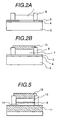
Fig. 5 shows a illustration view which is viewed
from a floating surface of the recording head which is
used the high resistivity film for one part of the upper
and lower part magnetic films.
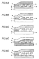
Figs. 6A, 6B, 6C, 6D, 6E are sectional views which
are viewed perpendicularly to a floating side of the
recording head which uses a high resistivity film and a
high saturation flux density film for one part of the
magnetic pole.
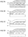
Figs. 7A, 7B, 7C, 7D are sectional views which are
viewed perpendicularly to a floating side of the recording
head which uses a high resistivity film for one part of
the magnetic pole.
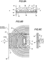
Figs. 8A, 8B are conception diagrams which show
magnetic head in the present invention.
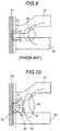
Fig. 9 is an illustration view to show a problem in
a conventional magnetic head.
Fig. 10 is an illustration view to show effect of
the present invention.
Fig. 11 are shematic views of the the magnetic pole
configuration viewed from a sliding surface side of the
conventional magnetic head.
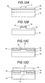
Figs. 12A, 12B, 12C, 12D are views for showing a
manufacture process for manufacturing a main part of the
magnetic head in the present invention.
Fig. 13 is a view for showing a manufacture process
for manufacturing a main part of the magnetic head in the
present invention.
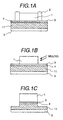
Figs. 14A, 14B show a recording reproducing head
which is used the high resistivity film or the high
saturation flux density film for one part of magnetic pole.
Fig. 15 is a perspective view of a
magnetoresistance effect element sensitive portion of a
spin valve type magnetic head relating to the present
invention.
Fig. 16 is a constitution view of the spin valve
film which used chrome - manganese alloying film /NiFe in
the present invention.
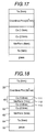
Fig. 17 is a constitution view of the spin valve
film which used chrome - manganese alloying film /Co in
the present invention.
Fig. 18 is a constitution view of a spin valve
magnetoresistance effect film used in the present
invention.
Fig. 19 shows a magnetic disc unit using a
recording reproducing head in the present invention.
DETAILED DESCRIPTION OF THE PREFERRED EMBODIMENT
(Embodiment 1)
Figs. 1A, 1B, 1C to Fig. 5 show the structures near
recording head portions of magnetic heads seeing from a
floating surface. Under an upper shield film 5 there is an
MR film or a GMR film which becomes a regenerating head
portion. The substrate is not specially limited, but it is
preferable that the substrate has a small surface
roughness (smaller than 5 nm).
As shown in Figs. 1A, 1B, 1C, a film of high
specific resistance (above 80 µΩ cm), Bs>1.5 T and
magneto-striction (absolute value)< 1X10⁻⁷ is formed in a
portion of the lower magnetic film by the sputtering
method, and a non-magnetic film having a thickness of 0.1
to 0.2 µm is formed thereon by the sputtering method to
be used as the gap film 4. As a magnetic film satisfying
the characteristics, a high specific resistance film can
be obtained by adding oxygen or nitrogen to an Fe, an
FeCo or an FeNiCo alloy and also adding an element having
a strong affinity with oxygen or nitrogen at the same time.
Further, the magneto-striction constant can be
controlled by adding the other alloy elements, and also
depends on concentration of oxygen or nitrogen. Further, a
base 3 for plated film is formed on the high specific
resistance film by the sputtering method.
This base 3 may be a high specific resistance film
and the film thickness is thinner than 100 nm. Resist
frames 2 are formed on the base 3, and the upper magnetic
film is formed by the plating method. The track width is
determined by the distance between the frames, and it has
been confirmed that the upper magnetic film can be
manufactured in 0.5 µm thickness without composition
variation through the frame plating method, and a head
having a track width of 0.5 to 1.5 µm has been
manufactured. A resist frame is manufactured by
masking with an oxide such as SiO2 through the RIE
(reactive ion etching) method. In the frame plating method,
it is an alloy film formed of the main component of Fe,
NiFe, CoFe or CoNiFe having a specific resistance smaller
than 60 µΩ cm. It is possible to obtain the structure
shown in Fig. 5 by forming a part of the upper magnetic
film manufactured through this plating method by a high
specific resistance film. Further, the side fringe can be
reduced by removing the base 3 and the gap film 4 and a
part of the lower magnetic film (the upper shield film of
MR or GMR) without reattaching through the milling method
or the RIE method with masking by the upper magnetic film
1. In a case of using the RIE method, it is possible to
etching nearly vertically with masking by the upper
magnetic film by optimizing the kind of gas, the gas
pressure and the etching rate. By setting the film
thickness of the high specific resistance film to 0.5 to 3
times as thick as the film thickness of the gap film, the
recording performance at high frequency can be suppressed
to be degraded. The film thickness of the upper magnetic
film is 2 to 3 µm, and it is difficult to form all of the
upper magnetic film by a high specific resistance plated
film. The reason is that the plating bath is difficult to
be controlled since a plated film satisfying all the
characteristics has a large film stress and consequently
various kinds of additives for high resistance and an
additive agent for stabilizing the plating bath are used,
and that the magneto-striction is more difficult to be
adjusted than in the sputtering method. However, it is
possible to manufacture the recording head having a
structure shown in FIG. 5 where a part of the upper
magnetic film is formed of a high specific resistance film.
As shown in Figs. 3A, 3B, 3C, it is possible that
the films in the upper side and in the lower side (the
upper
magnetic film 1 and the lower magnetic film 5) of
the
gap 4 are manufactured by the plating method, and the
high
specific resistance film 12 is manufactured on a part
of the frame and on the upper
magnetic film 1 by the
sputtering method. In this case, the gap film is a
conductive non-magnetic film (made of a Cr alloy or the
like). The frame is made of an oxide such as SiO
, and
there is no frame removing process as shown in FIG. 1, and
accordingly the frame remains on the floating surface as
it is. Further, the height of the frame may be a value
near the thickness of the upper
magnetic film 1. The
thickness of the upper
magnetic film 1 and the lower
magnetic film 5 is thinner than 3 times of the thickness
of the gap film.
As a recording head having a similar structure to
that of Figs. 3A, 3B, 3C, as shown in Figs. 2A, 2B, after
forming the
gap 4 and the
base 3 through the sputtering
method, the frame is formed by an oxide such as SiO
, and
a low specific resistance ferromagnetic film is formed as
the upper magnetic film through the plating method, and
further the high
specific resistance film 12 is formed on
a part of the frame and on the upper
magnetic film 1
through the sputtering method as similar to in Figs. 3A,
3B, 3C. In this case, since the width of the lower
magnetic film 5 is wider than the width of the upper
magnetic film 1 (the track width), the side fringe becomes
larger than in the other methods.
The structure of Fig. 4 is similar to that of Fig.
1, but a thin high specific resistance film 12 is also
formed on the gap 4 by plating method. The film thickness
is 0.5 to 3 times as thick as that of the gap. When the
film thickness is within this range, effect of high
specific resistance can clearly appear in the recording
performance and it can be manufactured by the plating
method. The high specific resistance plated film 12 is a
ferromagnetic allot film containing elements such as P, B,
O and so on. Further, as shown in FIG. 5, it is possible
that a part of an upper shield film 11 and a part of the
upper magnetic film 12 are formed by high specific
resistance (above 80 µΩ cm) film through the sputtering
method.
Fig. 5 is a configuration of the recording head
looked at from the floating side, and the configuration of
the surface which cuts off this head in a vertical
direction from floating side is shown in Fig. 6E.
The lower part magnetic pole and the upper part
magnetic pole are constructed to be a multilayer
configuration, and top and bottom magnetic films 13,14
that came in contact with the gap membrane 5 may be
provided by the galvanizing method.
The top and bottom magnetic film 13,14 are the membranes
added 3d transition metal chemical element to NiFe
alloying, CoNiFe- (Pt, Pd) alloying or alloying thereof.
The gap membrane may be made using flame same as
top and bottom magnetic film.
Magnetism characteristic of top and bottom magnetic
films 13,14 are Bs of more than 1.0 T, resistivity of less
than 60 µΩ cm, Hk of less than 20 Oe and magnetostriction
constant (lambda) of 1 × 10⁻⁵ or less.
Film thickness of the top and bottom magnetic film
13,14 is 3 times or more of the gap membrane respectively,
and the film thickness of the gap membrane is 0.1 µm.
The gap membrane is made of non-magnetic electrical
conduction membrane such as CrNi alloying, CuCr alloying,
NiW alloying or noble metal membrane.
High resistivity magnetic film 11,12 may be
provided by a suputtering method, and it is a laminating
layer of NiFe and Al2O3 membrane, a mixed layer of NiFe
membrane and Al2O3 membrane, or a mixed layer of NiFeN and
Al2O3 or a multilayer membrane of NiFeN and Al2O3, thereby
composition and membrane constitution thereof are
controlled so that the resistivity of the membrane becomes
to be higher than that of the top and bottom magnetic film
13,14.
As the technique of the multilayer or mixed layer
is used in order to make the resistivity high, the
saturation flux density ofthe membrane falls and becomes
smaller than that of the top and bottom magnetic film made
by the galvanizing method.
That is, the saturation flux density of the top and bottom
magnetic film 13,14 coming in contact with the gap becomes
higher than the high resistivity membrane.
In order to make the magnetic field strength on the
gap of the floating side higher, the high saturation flux
density membrane had better be disposed to the gap
membrane neighborhood as in the embodiment stated above.
The film thickness of the high resistivity membrane
12 is about 3 µm.
Moreover, the width of the high resistivity upper
part magnetic film 12 and the high resistivity lower part
magnetic film 11 is larger about 0.5 to 1 µm than the
membrane of the top and bottom magnetic film 13,14, and
the width of the top and bottom magnetic film is about 0.5
µm.
Except that flame of SiO2 is used in the galvanizing,
the regist flame is used and the regist is removed after
the galvanizing, and a part except the top and bottom
magnetic film 13,14 is covered with protective film (Al2O3
and SiO etc.), and a high resistivity hard magnetism
membrane of large width is formed on the top and bottom
magnetic film and the protective film.
A coil consists of two layers in Fig. 6E, however
one layer is capable to be used.
A sectional view in a vertical direction of a
sliding surface of the recording head is shown in Figs. 6A,
6B, 6C, 6D, 6E.
Figs. 6A, 6B, 6C, 6D, 6E respectively show
sectional views corresponding to Figs.1A, 1B, 1C, Fig. 2A,
2B, Fig. 3A, 3B, 3C, Fig. 4, Fig. 5.
In Fig. 6A, the upper part magnetic film consists
one layer of the magnetic film, the lower part magnetic
film consists of two layers of the magnetic films, and the
magnetic film near the gap membrane 56 of the lower part
magnetic film is high resistivity membrane.
The coil 55 is disposed between the insulation
membranes on the gap membrane 56, and the magnetic field
is generated from the floating side by flowing an electric
current in the coil.
In the configuration shown in Fig. 6B, the lower part
magnetic film consists one layer of the magnetic film, the
upper part magnetic film consists of two layers of the
magnetic films, and the magnetic film near the gap
membrane 56 of the upper part magnetic film is high
resistivity membrane is a high saturation flux density low
resistivity membrane 51.
The high saturation flux density low resistivity
membrane makes it with gilt method is made by the
galvanizing method and width of the magnetic film defines
the track width.
The high saturation flux density low resistivity
membrane is formed only by the floating side of the upper
part magnetic film, and the width of the high saturation
flux density low resistivity membrane viewed from the
floating side is narrower than the high resistivity
magnetic film 52 as to shown in Fig. 2.
The configuration shown in Fig. 6B is more suitable
to construct narrow track easily than the configuration
shown in Fig. 6A.
In Fig. 6C, the lower part magnetic film and the
upper part magnetic film consist of two layers of the
magnetic films.
The lower part magnetic film consists of the high
saturation flux density low resistivity membrane 51 and
the hard magnetism membrane 54 thereunder, and the upper
part magnetic film consists of the high saturation flux
density low resistivity membrane 51 and the high
resistivity magnetic film 52.
the high saturation flux density low resistivity membrane
51 and the gap membrane 56 are made by the galvanizing
method, and the high resistivity magnetic film 52 is made
by the suputtering method.
In the configuration shown Fig. 6C, Fig. 6E, the
saturation flux density low resistivity membrane is used
on and under the gap membrane 56, the width viewed at from
the floating side may be made narrower than the width of
other magnetic films, it is a configuration effective for
recording head having the narrow track, and the high
saturation flux density membrane is used for the gap
neighborhood. Therefore, the magnetic field strength
becomes higher, and radio frequency characteristic is good,
too as using the magnetic film of high resistivity.
Fig. 6D shows the high saturation flux density
membrane 51 forming the whole magnetic pole on and under
the gap membrane 56.
If only floating surface is formed to be the narrow
track shown in Fig. 4, the process which only the floating
side side is formed by the galvanizing method needs not to
be used.
Fig. 6E shows a similar configuration as Fig. 6C,
and the high saturation flux density low resistivity
membrane is used to came in contact with gap membrane 56,
and the high resistivity magnetic film 52 is used for the
magnetic pole material apart from and over and under the
gap, and the radio frequency characteristic thereof is
excellent, and the track width is capable to be less than
1.0 µm.
In respective Fig. 6A, Fig. 6B, Fig. 6C, Fig. 6D,
Fig. 6E, the high saturation flux density low resistivity
membrane 51 has higher saturation flux density than that
of the magnetic pole material used for other parts in each
recording head, and the resistivity thereof is smaller
than that of the material of other magnetic pole parts.
As the material used for the high saturation flux
density low resistivity membrane 51, for example, CoNiFe
alloying, NiFe alloying or the material which added 3d
transition metal chemical element in these alloying are
used.
As the gap membrane 56, the non-magnetic electrical
conduction membrane when making it by galvanising method,
oxide such as Al2O3 or SiO2 when making it by other methods,
or even nitride, carbide or any mixing material thereof
may be used.
Configuration examples of the recording head which is
similar to the configurations of Fig. 6A, Fig. 6B, Fig. 6C,
Fig. 6D, Fig. 6D are shown in , Fig. 7B, Fig. 7C, Fig. 7D.
In Fig. 7A, a magnetic film is provided on and
under the gap membrane 56 and apart therefrom as the high
resistivity magnetic film 52, the hard magnetism membrane
54 having smaller resistivity than that of the high
resistivity magnetic film 52 is disposed in the magnetic
gap side.
The volume of the high resistivity magnetic film 52
is larger than the volume of the hard magnetism membrane
54 having the low resistivity, and the radio frequency
characteristic is improved than that in the case that
there is not using the high resistivity membrane.
In Fig. 7B, the magnetic film which cames in
contact with a gap membrane and other gap membrane is
formed with the narrow track,and the magnetic film thereon
is constructed with the high resistivity magnetic film 52,
thereby good recording head of narrow track and radio
frequency characteristic may be offered.
In Fig. 7C, the upper part magnetic film consists three
layers, the gap membrane 56 is made at a flat part, the
magnetic film that width is narrow is provided thereon,
and the high resistivity magnetic film 52 is formed
through the magnetic film.
The hard magnetism membrane 54 having the low
resistivity is provided on the high resistivity magnetic
film 52, the magnetic field strength of the floating side
is capable to be high by making the saturation flux
density of the hard magnetism membrane 54 having this low
resistivity, higher.
The configuration resembled to Fig. 7C is a
recording head shown in Fig. 7D, and the upper part
magnetic films consists of the three laiyers the hard
magnetism membrane 54 of the low resistivity is provided
on a part near the gap membrane 56 and the high
resistivity magnetic film 52 is provided on a part being
far from the gap membrane, thereby the saturation flux
density of the material of the gap neighborhood is capable
to be higher than that in Fig. 7C, and the head that the
magnetic field strength is high may be offered.
Fig. 8 A shows a section of the magnetic head
having new configuration in the present invention.
A coil 26 is provided between the lower part core
25 and the upper part core 27, and consists of Al or Cu of
thickness 2µm.
An insulating material 31 of the non-magnetism is
filled up with an object to maintain the electric
insulation with the coil 26 and cores 25,27.
A coil 26 is enveloped between the lower core 25
and the upper core 27. The coil 26 is formed of an Al or
Cu film having thickness of 2 µm. A non-magnetic and
insulating material 31 is filled between the coil 26 and
the cores 25, 27 to electrically insulate between them.
The magnetic head in accordance with the present
invention is characterized by that magnetic pole members
32, 33 and an insulating and non-magnetic film 10 are
inserted between the upper core 27 and the lower core 25,
and a magnetic gap (or recording gap) is formed by these
members. Further, another characteristic point is that
magnetic path members 41, 42 are provided between the
upper core 27 and the lower core 25. This structure is not
a necessary structure to realize the present invention.
The magnetic path members 41, 42 are preferable to flatten
the upper core 27, and have an effect to reduce stress
(magneto-striction) remaining after manufacturing. By
forming the members together with the magnetic pole
members 32, 33, increase in manufacturing cost can be
prevented.
Fig. 8B is a view showing the magnetic head seeing
from the upper core side. It can be understood that the
coil 26 is wound in a spiral shape. The coil 26 is
connected to an electrode 30 (Fig. 8A) in a contact hall
34. Further, the upper core 27 and the lower core 25 are
connected in a magnetic contact hall 35. The magnetic
contact hall 35 is constructed including the magnetic path
members 41, 42 described above.
The insulating and non-magnetic film 10
characterized by the present invention is placed at a
position in the ends of the upper core 27 and the lower
core 25, and the structure of the members seeing from the
direction α is as shown by the Fig. 8C. That is, the
magnetic pole members 32, 33 having a narrow width are
interposed between the upper core 27 and the lower core 25,
and further the insulator non-magnetic film 10 is placed
between the members. The magnetic pole members 32, 33 are
magnetically integrated with the ends of the magnetic
poles of the upper core 27 and the lower core 25,
respectively. Therefore, the gap portion is formed by the
magnetic poles respectively having the projecting portion.
Further, Fig. 8C agrees with the magnetic pole
structure seeing from a plane of the magnetic head
accessing to the recording medium, and it can be
understood from the figure that the upper magnetic pole
has a projecting shape and the projecting portion is
formed toward the lower magnetic pole.
Further, from Fig. 8C, it can be understood that
both of the magnetic poles have a projecting shape, and
particularly the width of the projecting portion of the
upper magnetic pole is nearly equal to the width of the
projecting portion of the lower magnetic pole.
Furthermore, in the case of the present invention,
the height of the projecting portion is set to
approximately 0.8 µm, and the width of the projecting
portion is set to approximately 1 µm. From this
relationship, the height of the projecting portion is
lower than the width of the projecting portion.
The structure disclosed by the present invention
can be reduced the resistance of the magnetic path as the
same as that of Japanese Patent Application Laid-Open
No.7-296328. Description will be made, referring to Fig. 9.
The figure is a cross-sectional view of a conventional
magnetic head which does not have the magnetic pole
members 32, 33. The figure shows the magnetic gap put
between the lower core 25 and the upper core 27. Writing-in
magnetic flux to a medium 61 is conducted as a path
indicated by β. However, when the width of the gap
(magnetic pole width) of the end side of the upper core 27
is narrowed, the magnetic path resistance is increased and
by this effect the magnetic flux becomes to flow through a
path indicated by α in a region 50 where the magnetic path
resistance is increased. Thereby, an amount of the
magnetic flux conducted to the gap end portion 51 is
decreased and a necessary amount of magnetic flux cannot
be extracted from the gap (magnetic pole) ends.
On the other hand, in a case of the magnetic head
having the magnetic pole members 32, 33 shown in Fig. 10,
there are the magnetic pole members 32, 33 between the
upper core 27 and the lower core 25. Therefore, the path
α can be increased by thickness of the members (the non-magnetic
region can be widened). By this effect, it is
possible to suppress the amount of magnetic flux flowing
through the path α even if the magnetic path resistance is
increased by narrowing the width of the magnetic poles.
The above-mentioned effect can be observed in a
writing-in frequency above 150 MHz. This is an effect of
the present invention obtained by using the insulator non-magnetic
film in the magnetic gap. Further, in a case
where an amorphous high electric resistance magnetic film
such as CoTaZr or the like is used for the magnetic pole
material, the writing-in frequency can be increased up to
200 MHz.
In the structure disclosed in Japanese Patent
Application Laid-Open No.7-296328, since the trench
structure forming the projecting portions is made of a low
electric resistance material, eddy current is easily
generated in this portion and accordingly the upper limit
of the writing-in frequency is limited to 100 MHz.
As shown in Fig. 8C, the width w1 of the magnetic
pole members 32, 33 is narrower than the width of the
upper magnetic pole 27 and the width of the lower magnetic
pole 25. This is the base that the magnetic pole has the
projecting portion. By the effect of this shape, it is no
need to say that the magnetic flux is concentrated in the
projecting portions opposite to each other. Therefore,
under a condition that the magnetic field from the
projecting portion is adjusted so as to agree with the
magnetic field necessary writing-in by adjusting the coil
current (writing-in current), writing cannot occur in the
region except for the projecting portion (in the region
where the gap dimension becomes wide). Therefore, track
width to be written can be brought to agree with the width
of the projecting portion.
Further, in the present invention, only the
projecting portions may be made of a high electric
resistance and high saturation magnetizing material, and
thereby a strong magnetic field can be generate in the
region corresponding to the width of the projecting
portion. By this effect, the writing-in track width can be
efficiently limited to the width of the projecting portion
even if the magnetic pole has the projecting shape.
Further, since the height of the projecting portion
is lower than the width of the projecting portion, the
width of the projecting portion can be made smaller than 2
µm by a process to be described later. By this effect,
the width of writing in a medium can be easily reduced to
2 µm or smaller.
Furthermore, in the case of the present invention,
since the width of writing-in is determined by the width
of the projecting portion, there is no need to
particularly narrow the width of the upper core 27 and the
width of the lower core 25 in order to realize high
density recording. By this effect, the necessary magnetic
field can be efficiently conducted to the magnetic pole
end portion (the gap portion) without increasing the
magnetic path resistance.
In the case of the conventional magnetic head using
an insulator non-magnetic film in the magnetic gap, the
shapes of the magnetic heads can be roughly classified
into three kinds as shown in Fig. 11 when the magnetic
poles are seen from the sliding surface side. That is,
they are a magnetic head constructed by magnetic poles 27,
25 having different length as shown by Fig. 11A, a
magnetic head constructed by magnetic poles 27, 25 having
the same length as shown by Fig. 11B, and a magnetic head
having a projection in one of the magnetic poles 25. The
magnetic head Fig. 11B is an improved one of the magnetic
structure of Fig. 11B, and has a characteristic of small
magnetic field leakage in the track width direction since
the lengths of the magnetic poles are equal to each other.
Therefore, it is advantageous in writing for a narrow
track. However, this structure has a disadvantage in that
the magnetic pole 25 cannot be also used as a shield layer
to a magneto-resistance effect element. A countermeasure
of the disadvantage is the structure shown in Fig. 11C.
In order to realize the narrow track in the
structure shown in Fig. 11C, the width W needs to be
narrowed. Therefore, the writing-in magnetic flux is
decreased due to increase of the magnetic path resistance
shown in Fig. 9. Accordingly, it is impossible to write
high density information at a high efficiency.
Since in the structure in accordance with the
present invention the width of the writing-in gap portion
is limited by the width of the projection portion,
spreading of the leakage magnetic field toward the track
width direction is small as similar to in the magnetic
poles shown in Fig. 11B. Therefore, the structure in
accordance with the present invention is suitable for high
density recording. Further, since the width of the lower
core is wider than the width of the projecting portion,
there is no problem in that the lower core is also used as
a shield layer to a magneto-resistance effect element.
As having been described above, the magnetic head
structure in accordance with the present invention has no
problems in connection to high density recording which are
problems in the conventional magnetic head. A
manufacturing process of the magnetic head capable of
realizing the excellent performance will be described
below, referring to Fig. 12.
The figure shows features of forming the end of
magnetic pole of the magnetic core seeing from the
direction "α" shown in Fig. 8B. The processes will be
sequentially described below, referring to the figure.
In the process shown in Fig. 12A, a magnetic film
73 composing the lower magnetic pole is laminated on a
substrate (or a base layer or a base structure) 74. As the
magnetic film, a Ni-Fe alloy is used. The thickness is set
to 2 µm. On the magnetic film 73, an alumina film 72
having a thickness of 0.3 µm as an insulator non-magnetic
film is laminated and further a Ni-Fe magnetic alloy film
72 having a thickness of 0.8 µm is laminated. After
completion of laminating, a resist pattern 71 having a
width of the projecting portion (corresponding to the
writing-in track width) is formed through a photolithographic
method. The thickness is set to 1 µm.
Next, in the process shown in Fig. 12B, the
magnetic alloy film 72 is etched by an ion milling method
with masking of the resist pattern 71 to form a portion to
be formed in the projecting portion of the upper magnetic
pole. Then, the alumina film is etched by a chlorine and
fluorine reactive gas with masking of the resist pattern
71 and the projecting portion of the upper magnetic pole
formed by the etching. After that, a projecting portion is
formed in the lower magnetic pole by etching the lower
magnetic pole through the ion milling method with masking
of the member to be formed in the projecting portion of
the upper magnetic pole. In that time, the depth of the
etching is set to 0.8 µm. By etching the lower magnetic
pole through the ion milling method with masking of the
member to be formed in the projecting portion of the upper
magnetic pole, it is possible to form the projecting
portions having the same length opposite to each other.
This is effective to lessen spreading of the leakage
magnetic field in the track width direction, and is an
important element for functioning the present invention.
In the process shown in Fig. 12C, after laminating
a non-magnetic and insulating film 76 all over the surface,
the laminated non-magnetic and insulating film is
flattened and a part of the member 72 to form the
projecting portion is exposed. This process can be
realized by applying a fluid thermo-curing insulator used
in manufacturing of semiconductors (so-called spin-on-glass),
and performing the necessary heat treatment, and
then mechanically lapping the surface of the substrate. As
the other method, it is possible to use thermo-fluidity of
the resist.
It is a necessary condition for realizing the
present invention that the member 72 to form the
projecting portion is exposed from the insulator layer. If
a process can realize the necessary condition, the
flattening process of the insulator layer is not required.
For example, even if the thickness of the insulator member
76 exceeds the thickness of the member 72 to be formed in
the projecting portion, it has been confirmed that the
present invention is not affected. In such an extreme case
(a condition where the thickness of the insulator member
76 exceeds the thickness of the member 72 to be formed in
the projecting portion), an undulation is produced in the
upper magnetic pole and it results in that the projecting
portion exists in the depressed portion. This structure is
to be described in another part.
In the last process shown in Fig. 12D, the other
members composing the upper magnetic pole member is formed.
A Ni-Fe alloy film is used for the upper magnetic pole as
the same as in the conventional magnetic head.
By the processes described above, the magnetic
structure shown in Fig. 8C can be formed. Although the NI-Fe
alloy film is used for the material for the magnetic
pole in this embodiment, the magnetic head in accordance
with the present invention can be formed by using the
other soft magnetic film through the same process as in
this embodiment. Particularly, by using a high electric
resistant soft magnetic film, writing-in under a high
frequency condition can be realized. It is a
characteristic of the present invention that the soft
magnetic film can be formed depending on the eletroplating
method, and by this effect it is possible to perform
writing at a high frequency exceeding that of the
conventional magnetic head.
A structure of the upper magnetic pole having a
depressed portion will be described below. The structure
can be manufactured through processes of manufacturing a
magnetic head including at least the following process.
Description will be made, referring to Fig. 12 as similar
to the previous explanation.
As shown in Fig. 12A, after laminating a lower
magnetic material 73 on a base structure 74 of the
magnetic head, an insulator non-magnetic film 75 is
laminated and further a material 72 composing a part of
the upper magnetic pole is laminated.
Then, a resist pattern 71 is formed in a region
corresponding to the projecting portion of the upper
magnetic pole through a lithographic method.
Then, as shown in Fig. 12B, a projecting portion is
formed in the lower magnetic pole by etching the insulator
non-magnetic film and the lower magnetic pole with masking
of the resist pattern 71 and the member to be formed in
the projecting portion of the upper magnetic pole.
After that, as shown in Fig. 12C, after forming
members to be formed in the projecting portions in the
upper and the lower magnetic poles, a non-magnetic and
insulating film 76 with a thickness exceeding the
projecting portion is laminated over the region except for
the projecting portion. Although the figure shows that the
surface of the insulator non-magnetic film 76 and the
surface of the projecting portion (the surface of 72) seem
to be in the same level, in this embodiment the thickness
of the insulator non-magnetic film 76 exceeds the surface
of the projecting portion (the surface of 72).
Then, by forming the other members 77 remaining
part of the upper magnetic pole member as shown in Fig.
12D, the objective magnetic pole shape of the magnetic
head is manufactured.
Fig. 13 shows the magnetic pole shape of the
magnetic head manufactured through the manufacturing
processes including at least the above-mentioned process.
The figure clearly shows the shape of the upper magnetic
pole 77 having the projecting portion in the depressed
portion.
It should be added to describe that this shape is
highly efficient for efficiently conducting the magnetic
flux of the upper magnetic pole into the projecting
portion.
The magnetic head in accordance with the present
invention is formed on a wafer obtained by machining a
sintered body of alumina and titanium carbide. Then, after
performing desired machining, a magnetic head slider is
manufactured.
According to the above-mentioned processes, the
width of the projecting portion determining the writing-in
track width is determined by the width of the resist
pattern. However, by making the height of the magnetic
pole projecting portion of the present invention lower
than the width of the projecting portion, a resist pattern
having a thick film thickness is not always necessary.
From this effect, patterning resolution is easier compared
to the resist pattern of a plating mask pattern, and the
width of the projecting portion can be made smaller than 2
µm. By this characteristic, a magnetic head used for
narrow track can be easily manufactured.
By employing a head slider composed of the magnetic
head, it is possible to attain high density recording of a
track width smaller than 2 µm. By this effect, it is
possible to realize a high density magnetic recording
apparatus of 5 Gb/in2 or more which has been thought
impossible to be realized. This is an effect that the
magnetic flux can be efficiently conducting up to the end
portion of the magnetic pole, and the effect is produced
by that the ends of the magnetic poles are constructed by
the magnetic poles respectively having the projecting
portion.
(Embodiment 2)
Fig. 14 shows an example of a recording reproducing
head in which the high resistivity membrane as shown in
the embodiment 1 is used for the recording head and the
recording head is combined with a reproducing head as
shown in the following.
A huge magnetoresistance effect membrane 104 is
used for the reproducing head, an electrode 105 to flow an
electric current contacts with the huge magnetoresistance
effect membrane 104 electrically.
There is provided a lower part shielding membrane
106 through the lower part gap membrane under electrode
105 and the huge magnetoresistance effect membrane 104.
A high resistivity lower part magnetic film 108 is
disposed as the upper part shielding membrane through the
upper part gap membrane on the huge magnetoresistance
effect membrane 104, and the high resistivity lower part
magnetic film 108 consists of one part of the lower part
magnetic pole of the recording head.
By constituting one part of this high resistivity
lower part magnetic film 108 with the high resistivity
membrane, the radio frequency characteristic of the
recording head may be improved.
The width of the gap membrane 102 of recording head
is equal to that of the magnetic films disposed on and
under the addition, and the high saturation flux density
membranes 101,103 on and under the gap are desirable to be
constructed with a material of higher saturation flux
density than that of other magnetic pole parts.
A high resistivity upper part magnetic film 107
having a larger width is used on this high saturation flux
density membrane 101.
An electric current is flown in the coil 109 of the
recording head, and the recording media 110 is recorded by
a magnetic field from the recording head.
In addition to above, a head of the different
configuration used to a hard magnetism tunnel membrane may
be used for the reproducing head.
Fig. 15 is a partial sectional view of the magnetic
head (MR sensor) using a spin valve magnetoresistance
effect membrane in the present invention.
MR sensor in the present invention has a
configuration which sticks the second magnetic layer 22 of
first magnetic layer 45 of soft ferromagnetic body, non-magnetic
metal layer 21 and ferromagnetic body, on an
appropriate substrate 43 as glass or ceramic.
In the yhard magnetism layer 45 and 22, individual
magnetisation directions thereof become to cross with
about 90 degrees angle differential when the magnetic
field is not applied.
Magnetization direction of the second magnetic
layer 22 is fixed to the same direction as a magnetic
field direction of the magnetic media.
The magnetization direction of the first magnetic
layer 45 of the soft ferromagnetic body when the magnetic
field is not applied inclines 90 degrees to the magnetic
field direction of the second magnetic layer.
A magnetization rotation occurs with the first
magnetic layer 45 responding to the applied magnetic field.
The first magnetic layer 45, the non-magnetic metal
layer 21, the second magnetic layer 22 and the
antiferromagnetic substance layer 23 explained in the
embodiment of the present invention are capable to use a
membrane constitution as the laminating configuration
shown by later Fig. 16, Fig. 17 and Fig. 18, and moreover
as the hard magnetism layer 47, Co82 Cr9 Pt9, Co80 Cr8
Pt9(ZrO2)3 may be used.
These Fig. 16, Fig. 17 and Fig. 18 show the first
magnetic layer 45 in this embodiment and a membrane
constitution equivalent to the second magnetic layer 22
and those magnetic field directions are formed same as the
said article.
Before adhering the first magnetic layer 45 of the soft
ferromagnetic body in this embodiment, an appropriate
lower part membrane 24, for example, such as Ta, Ru or CrV
is stuck on a substrate 43.
An object to stick the lower part membrane 24 is in
optimizing formation, grain size number and a form of the
layer stuck later.
The form of the layer is very important to get
suitable MR effect.
Furthermore, it is because the a very thin distance piece
layer of the non-magnetic metal layer 21 may be utilized
by the formation of the layer.
In order to make affection by a branch minimum
furthermore, a high electric resistance is preferable to
be used as the lower part layer.
The lower part layer may be used as a reverse
configuration as mentioned above.
Substrate 43 is made of a sufficient high electric
resistance and a plane fully and in case of appropriate
crystal structure, the lower part membrane 24 is
unnecessary.
As the first magnetic layer 45, means for producing
a bias in a londitudinal direction is used in order to
maintain a single domain condition in a direction to be
parallel to this page.
As the means for producing the bias in the londitudinal
direction, a rigid hard magnetism layer 47 having
characteristics of high saturation coercive force, high
right angle degree, high electric resistance is used as
well.
The rigid hard magnetism layer 47 contacts with a domain
of an end of the first magnetic layer 45 made of the soft
ferromagnetic body.
Magnetization direction of the rigid hard magnetism
layer 47 is parallel to this page.
The first antiferromagnetism layer contacts with
the domain of the end of the magnetic layer 45 so as to be
stuck, and a necessary bias in a londitudinal direction
occurs.
The antiferromagnetism layer is preferrable to have
a blocking temperature which is sufficientry different
from that of an antiferromagnetism layer 23 which is used
in order to let the magnetization direction of the second
magnetic layer 22 made of the ferromagnetic body, fixed.
In the next, a capping layer made of the high
resistance such as Ta, for example, is desirable to be
stuck on all of the upper part of the MR sensor.
An electrode 28 is provided, and a circuitry is formed
between the MR sensor structure, the current source and
the detection means.
Fig. 16 to Fig. 18 respectively show a membrane
constituting a magnetoresistance effect element in the
present invention formed in stead of each membrane of the
non-magnetic metal layer 21, the second magnetic layer 22
and the antiferromagnetic substance layer 23 shown in Fig.
15, and it is formed by a radio frequency magnetron
suputtering apparatus as follows.
In the atmosphere of Ar 3 mm torr, following
materials are successively laminated on a ceramics
substrate of a thickness 1 mm, a diameter of 3 inches.
As a suputtering target, tantalum, nickel -20at %
ferrum alloying, copper, cobalt, chrome -50at % manganese
are used.
In order to manufacture a chrome - manganese alloying
membrane, a chip of 1 cm × 1 cm of an additional element is
arranged on a chrome - manganese target top, and number of
the chip is increased or decreased so as to adjust the
composition thereof.
Moreover, when Co-Fe-Ni layer is made as the hard
magnetism membrane, the chip of 1 cm × 1 cm of nickel,
ferrum is arranged on the cobalt target top to adjust the
composition.
Each layer of the laminating film is formed
successively by generating Plasma in the apparatus by
applying a radio frequency electric power on the cathode
arranging each target, and opening and shutting a shutter
arranged in every each cathode.
In the film formation, applying a magnetic field of
about 30 Oe in parallel to the substrate by using a
permanent magnet one axes anisotropism is provided, and
the direction of the replacement coupling magnetic field
of the chrome-manganese film is guided to a direction of
theapplied magnetic field, and an example of the formation
condition stated above is shown by a table 1 as follows.
| Layer | Ar gas pressure | rf output | Forming speed |
| Ta: | 0.8 m Torr | 300 W | 0.25 nm/s |
| NiFe: | 3 m Torr | 350 W | 0.17 nm/s |
| Cu: | 3 m Torr | 150 W | 0.2 nm/s |
| CrMnPt: | 8 m Torr | 350 W | 0.5 nm/s |
| Co: | 3 m Torr | 250 W | 0.13 nm/s |
A laminating film is heat-treated in a vacuum
thermal treatment equipment after being formed.
The heat treatment is performed by raising the
temperature up from the room temperature a predetermined
temperature, for example 250 °C, and after holding the
temperature for a predetermined time, for example one hour,
cooling off to a room temperature.
In total process of the temperature raising,
holding and cooling, the magnetic field from 2 to 5 k Oe
is applied in parallel to the surface of the substrate.
A direction of the above magnetic field is parallel
to the magnetic field applied by the permanent magnet when
forming the film.
Formation of the element on the substrate is
performed by a photo resist production process.
After that, the substrate is processed by a slider,
and is loaded in the magnetic recording apparatus.
Fig. 16 is a figure comparing characteristics
before the heat treatment and after the heat treatment the
spin valve film which has the magnetic laminating body
using the antiferromagnetism film of 45 at % chrome -45
at % manganese -10 at % platina/81 at % Ni-19 at % Fe film.
The coupling magnetic field by one direction
anisotropism appear as a shift quantity of a right side
loop of the figure.
The coupling magnetic field before heat treatment is 300
Oe, 250 °C, and 380Oe after the heat treatment of three
hours.
Considering the thickness of Ni Fe layer and the size of
the magnetization, it is same size with the dimension
shown in the prior art.
Fig. 17 is a figure comparing characteristics
before the heat treatment and after the heat treatment of
the spin valve film which has the magnetic laminating body
using the antiferromagnetism film of 45 at % chrome -45
at % manganese -10 at % platina/ Co film.
The coupling magnetic field before the heat
treatment is almost similar to that in the case shown in
Fig. 1 with 300 Oe,
after the heat treatment for three hours in 250 °C, the
coupling magnetic field becomes 600 Oe, about two times
than before.
Considering the thickness of the Co layer and the size of
the magnetization, it is size of about two times of the
coupling magnetic field shown by Fig. 1.
Fig. 18 is an other constitution example in the
present invention using a magnetic laminating body as the
spin valve magnetoresistance effect film,
The antiferromagnetism film 30 (45 at % Cr-45 at %
Mn-10 at % Pt) and the hard magnetism layer 65 sticking
thereto respectively consist of a Co layer 111 directly
connected to the antiferromagnetism film 30, the soft
magnetism layer 112 having a good magnetism characteristic
(81 at % Ni-19 at % Fe), and a Co layer 113 directly
contacting with the non-magnetic layer 62 (Cu) and
producing huge magnetoresistance effect.
A foundation film 64 is the foundation layer for
controlling orientation and crystal grain size of other
film, and a soft magnetism layer 63 (81 at % Ni-19 at %
Fe) is a free layer.
The Co layer is arranged at a joint portion with
the antiferromagnetism film and a jointportion with the
non-magnetic film, however the magnetism characteristic of
the hard magnetism layer 65 as the fixed layer is not
deteriorated, and thickness and characteristic of the hard
magnetism layer 65 may be held without increasing the
magnetization quantity of the total layer.
Accordingly, the soft magnetism layer 112 is
desirable to have a good magnetism characteristic and to
have a smaller saturation flux density than those of the
layers 113 and 111 consisting of Co, for example, Ni 81 Fe
19 film of the saturation flux density of 1 Tesla.
Furthermore, the saturation flux density may be
fallen to be even 0.5 Tesla or so, and for example, NiFe-Cr
film is suitable, too, this NiFe-Cr film consists of
NiFe alloying containing 0 to 20 at % Cr, and this NiFe
alloying consists of 75-95 at % Ni and remainder Fe.
(Embodiment 3)
Fig. 19 is a total figure of the magnetic disc unit
using the recording reproducing sectional pattern head
shown in the embodiment 2.
Recording reproducing separating type magnetic head
201 is controlled a location on a recording media 203 by
head positioning frame 202 on the recording media 203 as a
magnetic disk turned by a motor, and the recording
reproducing separating type magnetic head 201 is
connected with a regenerative signal processor 204.
This apparatus consists of a DC motor for turning
the magnetic disk, a magnetic head to write in information
and to read it, a positioning apparatus to support the
magnetic head and to change a location thereof to the
magnetic disk, that is an actuator and voice coil motor,
and an air filter to keep the apparatus inside cleanly.
The actuator consists of a carriage, a rail, and a
bearing, and the voice coil motor consists of a voice coil
and a permanent magneto.
In this figure, eight pieces of magnetic disk are
installed in a same rotation axis, an example which
thereby has a big storage capacity is shown.
Magnetic disk is constructed with a good surface
having surface roughness R MAX of 100 Å or less,
preferably of 50 Å or less.
The magnetic disk has the magnetic recording layer
formed by a vacuum film formation method on the surface of
the hard substrate.
The magnetic thin film is used for the magnetic
recording layer.
Because the film thickness of the magnetic
recording layer formed by the vacuum film formation method
is 0.5 µm or less, the surface condition of the hard
substrate is just reflected as that of the recording layer.
Accordingly, one having the surface roughness R MAX
of 100 A or less is used for the hard substrate.
As such hard substrate, glass, chemical strengthen
soda-almina silica glass or ceramic are used as a main
component thereof.
Moreover, in case of the magnetic layer made of
metal or alloying, it is preferable to provide the oxide
layer or nitride layer on the surface, or for the surface
with an oxide film.
Moreover, use of carbon protective coat is desirable, too.
By forming the head in this way, durability of the
magnetic recording layer is improved, and damage of the
magnetic disk may be prevented in a case that it is
recorded and reproduced with a extremely low floating
quantity, or in a contact, a start, and a stop.
As a result of having measured performance of the
recording head by the present invention (overwrite
characteristic) stated above, even in a radio frequency
domain of 40 MHz or more, a superior recording performance
as about -50dB is provided.
According to this embodiment, for high coercive
force media, it can be recorded fully even in the radio
frequency domain , and MR sensor of high sensitivity is
provided, having excellent MR effect based on the
anisotropism magnetoresistance effect, such as media
transfer rate 15MB/second or greater, recording frequency
45 MHz or more, high-speed transmitting of the data more
than magnetic disk 4000 rpm, abbreviation of access time,
increase of recording capacity, thereby, a magnetic disc
unit with 3Gb/ in2 or greater is provided as surface
recording density.
According to the present invention as stated above,
at least one part of the magnetic pole of the recording
head is made of high resistivity film, and as the
recording performance is hard to fall in the radio
frequency, a magnetic storage apparatus of high recording
density is provided.
Furthermore, according to the present invention, a
magnetic laminating body which had a sufficient coupling
magnetic field and a high temperature stability may be
provided, thereby, a reproducing head which has a
sufficient reproducing capacity and low noise
characteristic and a high density magnetic storage
apparatus of high reliability may be provided.