EP0851172A2 - Burner for operating a combustion chamber with a liquid and/or gaseous fuel - Google Patents
Burner for operating a combustion chamber with a liquid and/or gaseous fuel Download PDFInfo
- Publication number
- EP0851172A2 EP0851172A2 EP97810838A EP97810838A EP0851172A2 EP 0851172 A2 EP0851172 A2 EP 0851172A2 EP 97810838 A EP97810838 A EP 97810838A EP 97810838 A EP97810838 A EP 97810838A EP 0851172 A2 EP0851172 A2 EP 0851172A2
- Authority
- EP
- European Patent Office
- Prior art keywords
- burner
- flow
- zone
- air
- burner according
- Prior art date
- Legal status (The legal status is an assumption and is not a legal conclusion. Google has not performed a legal analysis and makes no representation as to the accuracy of the status listed.)
- Granted
Links
Images

Classifications
-
- F—MECHANICAL ENGINEERING; LIGHTING; HEATING; WEAPONS; BLASTING
- F23—COMBUSTION APPARATUS; COMBUSTION PROCESSES
- F23D—BURNERS
- F23D17/00—Burners for combustion simultaneously or alternately of gaseous or liquid or pulverulent fuel
- F23D17/002—Burners for combustion simultaneously or alternately of gaseous or liquid or pulverulent fuel gaseous or liquid fuel
-
- F—MECHANICAL ENGINEERING; LIGHTING; HEATING; WEAPONS; BLASTING
- F23—COMBUSTION APPARATUS; COMBUSTION PROCESSES
- F23C—METHODS OR APPARATUS FOR COMBUSTION USING FLUID FUEL OR SOLID FUEL SUSPENDED IN A CARRIER GAS OR AIR
- F23C7/00—Combustion apparatus characterised by arrangements for air supply
- F23C7/002—Combustion apparatus characterised by arrangements for air supply the air being submitted to a rotary or spinning motion
-
- F—MECHANICAL ENGINEERING; LIGHTING; HEATING; WEAPONS; BLASTING
- F23—COMBUSTION APPARATUS; COMBUSTION PROCESSES
- F23C—METHODS OR APPARATUS FOR COMBUSTION USING FLUID FUEL OR SOLID FUEL SUSPENDED IN A CARRIER GAS OR AIR
- F23C2900/00—Special features of, or arrangements for combustion apparatus using fluid fuels or solid fuels suspended in air; Combustion processes therefor
- F23C2900/07002—Premix burners with air inlet slots obtained between offset curved wall surfaces, e.g. double cone burners
-
- F—MECHANICAL ENGINEERING; LIGHTING; HEATING; WEAPONS; BLASTING
- F23—COMBUSTION APPARATUS; COMBUSTION PROCESSES
- F23D—BURNERS
- F23D2209/00—Safety arrangements
- F23D2209/10—Flame flashback
Definitions
- the present invention relates to a burner according to the preamble of claim 1.
- Step on the outer boundary of the swirl flow field particularly low speeds because at constant Total pressure in the arrangement of the static pressure from the inside to the outside, causing the dynamic pressure caused by the absolute speed is represented with increasing Radius is getting smaller. These low speeds may no longer be able to prevent the flame from the combustion chamber, along the boundary layer, into the burner reproduces and can then overheat and destroy it.
- the invention seeks to remedy this.
- the invention how it is characterized in the claims, the task lies based on precautions for a burner of the type mentioned to meet those who are capable of a flashback to prevent safely.
- the main advantage of the invention is that that this additional device of the simplest design is, and be installed as required in the burner mentioned can intervene without changing the basic concept of the same to have, with which such a burner, which is at medium compressor pressure ratios already well proven has, also for the further development stages of Gas turbines can be taken over and used.
- additional air is injected along made of the burner walls, preferably in the downstream half of the burner.
- This additional air forms a film along the wall and mixes it then slowly with the fuel-enriched main flow.
- the essential improvement in security against one Backfire is based on two principles.
- the mixture is diluted with weight. There the burner is operating near its lean extinguishing limit weak local dilution of the mixture results along the walls to the desired loss of flammability of the mixture along the walls.
- this additional air is injected so that the axial speed is increased along the wall, which is also convenient affects the operation of such a burner.
- the pulse density ratio between film air and main flow in the range of 1 since both flows are common be accelerated from the same total pressure. Other impulses are also easily conceivable, they have striven for Effect no negative effects.
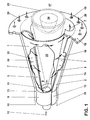
- Fig. 1 shows a burner in perspective.
- Fig. 2 For a better understanding of the subject, it is advantageous if at the same time when studying Fig. 1 based on the description Fig. 2 is also used.
- Partial bodies 1, 2 which are nested offset from one another are.
- the offset of the respective central axis or Longitudinal axis of symmetry of the partial bodies 1, 2 to one another creates on both sides, in mirror image Arrangement, each having a tangential air inlet duct 5, 6 free, through which the combustion air 7 in the interior of the Brenner, i.e.
- the two tapered Partial bodies 1, 2 each have a cylindrical initial part 9, 10, which also, analogously to the aforementioned partial bodies 1, 2, offset to each other, so that the tangential Air inlet channels 5, 6 over the entire length of the Brenners are present.
- a nozzle 11 for preferably atomizing a liquid fuel 12 housed such that their injection approximately with the narrowest cross section of the the partial body 1, 2 formed conical cavity 8 coincides.
- the injection capacity and the operating mode of this Nozzle 11 depends on the given parameters of the respective Brenners.
- the fuel injected through the nozzle 11 12 can be enriched with a recirculated exhaust gas if necessary will; then it is also possible to pass through the nozzle 11 to provide the complementary injection of a quantity of water.
- the burner can be purely conical, that is, without cylindrical starting parts 9, 10 may be formed.
- the partial body 1, 2 each have a fuel line 13, 14, which along the tangential inlet channels 5, 6 arranged and provided with injection openings 15, through which preferably a gaseous fuel 16 in the combustion air 7 flowing there is injected, as this is symbolized by arrows 16, these Injection at the same time the fuel injection level (see Fig. 3, item 22) of the system.
- These fuel lines 13, 14 are preferably at the latest at the end of the tangential inflow, before entering the cone cavity 8, placed this to ensure an optimal air / fuel mixture.
- the burner On the combustion chamber side, the burner has an anchor for the partial body 1, 2 serving front panel 18 with a number Bores 19 through which a mixing or Cooling air 20 or the front part of the combustion chamber 17 Wall is fed.
- Liquid fuel 12 is used to operate the burner the central nozzle 11 is used, this is under one acute angle in the cone cavity 8 or in the combustion chamber 17 injected. A nozzle is thus formed from the nozzle 11 Fuel profile 23, which flows in from the tangential rotating combustion air 7 is enclosed. In axial Direction is the concentration of the injected fuel 12 continuously through the incoming combustion air 7 an optimal mixture degraded. If the burner with a operated gaseous fuel 16, this can in principle also happen via the fuel nozzle 11, preferably but this happens via the injection openings 15, whereby the formation of this fuel / air mixture right at the end the air inlet channels 5, 6 comes about.
- a backflow zone also forms there or backflow bladder 24 (vortex breakdown) with one opposite the flame front 25 acting there stabilizing Effect one, in the sense that the backflow zone 24 has the function of a disembodied flame holder.
- the optimal fuel concentration across the cross-section is only in the area of vertebral bursting, i.e. in the area the backflow zone 24 reached. Only at this point then a stable flame front 25.
- the flame stabilizing Effect results from that in the cone cavity 8 forming swirl number in the direction of flow along the cone axis. The flame strikes back inside the burner therefore occurs due to this fluidic specification not on.
- the flow opening is minimized of the tangential air inlet ducts 6, 7 is predestined is the backflow zone 24 from the end of the premixing section to build.
- the construction of the burner is suitable furthermore excellent, the flow opening of the tangential To change air inlet channels 5, 6 as required, with what a relative without changing the overall length of the burner large operational bandwidth can be captured.
- the partial body 1, 2 in another Plane can be shifted towards each other, which even overlaps opposite the air inlet plane into the cone cavity 8 (See FIG. 2, item 21) of the same in the area of the tangential Air inlet channels 5, 6, as shown in Fig. 2, accomplished can be. It is then also possible that Partial body 1, 2 by a counter-rotating movement to nest in a spiral.
- Fig. 2 shows the same burner according to Fig. 1 but from a different one Perspective and in a simplified form.
- This figure 2 mainly wants the disposition of the two conical ones Show part body 1, 2 and their offset to each other.
- the Displacement of the respective central axis 3, 4 of the two partial bodies to each other, based on the main central axis 26 of the Burner, which is the main axis of the central fuel nozzle 11 corresponds to the respective size of the flow openings the tangential air inlet ducts 5, 6.
- the central axes 3, 4 run parallel to each other here.
- Zone 27 in which the placements of Means for the injection of additional air takes place.
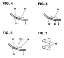
- FIGS. 4 and 5 show a development 28 of a conical partial body, which schematically shows zone 27 within which has a specific configuration of injection openings for additional air, which ensure a reignition lock, is taken as a basis.
- the orientation of the injection openings 29 as well as their number and size will be the respective Flow conditions in the burner adjusted.
- the final Purpose is primarily aimed at the reignition barrier.
- the individual oblique lines 30 want the placement of the symbolize individual rows of the injection openings 29.
- the arrows 31 point to the outflow direction of the Additional air indicate that is at right angles to the Level 30 of the injection openings 29 runs. This outflow direction can, however, range from purely axial to direction the main flow vary. For better understanding are in this processing 28 a single row and one Double row of injection openings 29 shown. The corresponding cuts are then shown in FIGS. 4 and 5.
- Fig. 4 shows the design of a simple row of injection openings 29.
- the additional air 32 is here under one injected acute angle with respect to the swirl flow 7a flat to the inner wall of the corresponding partial body 2, this around improve film production.
- FIG. 5 shows a double row of injection openings 29. Basically, the same precautions are taken here as described in Fig. 3.
- the injection openings 33 run in the area the inner wall of the corresponding partial body 2 fan-shaped, as shown in Fig. 7, which is a plan view.
Landscapes
- Engineering & Computer Science (AREA)
- Chemical & Material Sciences (AREA)
- Combustion & Propulsion (AREA)
- Mechanical Engineering (AREA)
- General Engineering & Computer Science (AREA)
- Gas Burners (AREA)
- Pre-Mixing And Non-Premixing Gas Burner (AREA)
Abstract
Description
Die vorliegende Erfindung betrifft einen Brenner gemäss Oberbegriff
des Anspruchs 1.The present invention relates to a burner according to the preamble
of
Bei Brennern für eine Vormischverbrennung von flüssigen und/oder gasförmigen Brennstoffen bildet das Hineinwandern der Flamme in den Brenner, auch Flammenrückschlag bezeichnet, ein Hauptproblem. Daneben muss die Aerodynamik bei diesen Brennern so ausgelegt werden, dass lokale Gebiete hoher Aufenthaltszeit, in denen das Brennstoff/Luft-Gemisch zünden kann (= Selbstzündung), vermieden werden. Wird eine Drallströmung so erzeugt, dass in der Nähe der Achse hohe Umfangsgeschwindigkeiten auftreten, beispielsweise wenn radiale Drallregister zur Anwendung gelangen, so ist die Axialgeschwindigkeit im Zentrum niedrig. Da gleichzeitig hohe Turbulenzgrade auftreten, kann sich die Flamme entgegen der Strömungsrichtung ausbreiten und wandert dann in den Brenner, wobei in der Folge im allgemeinen Ueberhitzungsprobleme auftreten. In der Praxis führt dies zu Einschränkungen bei der Wahl der Drallerzeugung. Die Erzeugung eines Drallströmungsfeldes erfordert das Einschliessen der Strömung in einen am besten rotationssymmetrischen Raum. Die äussere Begrenzung dieses Raumes verursacht eine Strömungsgrenzschicht, welche immer die Bedingung verschwindender Geschwindigkeit an der Wand hat. Gleiches gilt für im Zentrum eingebaute Brennstoff lanzen. Der Teil des Gemisches, der direkt entlang der Wand strömt, wird sich unerwünscht lange im Brenner aufhalten. An der äusseren Begrenzung des Drallströmungsfeldes treten besonders niedrige Geschwindigkeiten auf, da bei konstantem Totaldruck in der Anordnung der statische Druck von innen nach aussen ansteigt, womit der dynamische Druck, der durch die Absolutgeschwindigkeit repräsentiert wird, mit steigendem Radius immer kleiner wird. Diese niedrigen Geschwindigkeiten können unter Umständen nicht mehr verhindern, dass die Flamme vom Brennraum aus, entlang der Grenzschicht, in den Brenner fortpflanzt und diesen dann überhitzen und zerstören kann.For burners for premix combustion of liquid and / or gaseous fuels forms the immigration the flame into the burner, also known as flashback, a major problem. In addition, the aerodynamics in these Burners are designed so that local areas with a long in which ignite the fuel / air mixture can be avoided. Will a swirl flow generated so that high peripheral speeds near the axis occur, for example when radial Swirl registers are used, so is the axial speed low in the center. Because at the same time high levels of turbulence occur, the flame can move against the direction of flow spread out and then migrates into the burner, being subsequently general problems of overheating occur. In practice, this leads to restrictions the choice of swirl generation. The generation of a swirl flow field requires the flow to be enclosed in one preferably rotationally symmetrical space. The outer limitation this space creates a flow boundary layer, which always the condition of vanishing speed at the Has wall. The same applies to fuel installed in the center lance. The part of the mixture that is directly along the Wall flows, will remain in the burner for an undesirably long time. Step on the outer boundary of the swirl flow field particularly low speeds because at constant Total pressure in the arrangement of the static pressure from the inside to the outside, causing the dynamic pressure caused by the absolute speed is represented with increasing Radius is getting smaller. These low speeds may no longer be able to prevent the flame from the combustion chamber, along the boundary layer, into the burner reproduces and can then overheat and destroy it.
Aus EP-B1-0 321 809 ist ein Brenner bekanntgeworden, der unter Vormischbedingungen für flüssige und/oder gasförmige Brennstoffe die bis anhin bestbekanntgewordene Lösung auf diesem Gebiet darstellt, um die obengenannten Unzulänglichkeiten ohne Implemetierung von Zusatzeinrichtungen beheben zu können.From EP-B1-0 321 809 a burner has become known, which under Premixing conditions for liquid and / or gaseous Fuels the best known solution to date this area represents to the above shortcomings without having to implement additional equipment can.
Allerdings geht die Entwicklung im Gasturbinenbau dahin, die Kompressordruckverhältnisse kräftig zu steigern, so dass die Zuverlässigkeit des obengenannten Brenners aus genannten Gründen automatisch gemindert wird.However, the development in gas turbine construction continues Boost compressor pressure ratios so that the Reliability of the above-mentioned burner from Reasons is automatically reduced.
Hier will die Erfindung Abhilfe schaffen. Der Erfindung, wie sie in den Ansprüchen gekennzeichnet ist, liegt die Aufgabe zugrunde, bei einem Brenner der eingangs genannten Art Vorkehrungen zu treffen, welche in der Lage sind, einen Flammenrückschlag sicher zu verhindern.The invention seeks to remedy this. The invention how it is characterized in the claims, the task lies based on precautions for a burner of the type mentioned to meet those who are capable of a flashback to prevent safely.
Der wesentliche Vorteil der Erfindung ist darin zu sehen, dass diese Zusatzeinrichtung von einfachster Ausgestaltung ist, und im genannten Brenner bedarfsmässig eingebaut werden kann, ohne auf die Grundkonzeption desselben verändernd eingreifen zu müssen, womit ein solcher Brenner, der sich bei mittleren Kompressordruckverhältnissen bereits bestens bewährt hat, auch für die weiteren Entwicklungsstufen von Gasturbinen übernommen und eingesetzt werden kann.The main advantage of the invention is that that this additional device of the simplest design is, and be installed as required in the burner mentioned can intervene without changing the basic concept of the same to have, with which such a burner, which is at medium compressor pressure ratios already well proven has, also for the further development stages of Gas turbines can be taken over and used.
Erfindungsgemäss wird eine Eindüsung von Zusatzluft entlang der Brennerwände vorgenommen, und zwar vorzugsweise in der abströmungsseitigen zweiten Hälfte des Brenners. Diese Zusatzluft bildet entlang der Wand einen Film und sie vermischt sich dann langsam mit der brennstoffangereicherten Hauptströmung. Die wesentliche Verbesserung der Sicherheit gegen eine Rückzündung erfolgt aufgrund von zwei Prinzipien. Zum einen wird gewichtig eine Verdünnung des Gemisches vorgenommen. Da der Brenner in der Nähe seiner mageren Löschgrenze betrieben wird, führt schon eine schwache lokale Verdünnung des Gemisches entlang der Wände zum erwünschten Verlust der Brennfähigkeit des Gemisches entlang der Wände. Zum anderen kann diese Zusatzluft so eingedüst werden, dass die Axialgeschwindigkeit entlang der Wand erhöht wird, was sich ebenfalls günstig für den Betrieb eines solchen Brenners auswirkt. Im allgemeinen ist das Impulsdichtenverhältnis zwischen Filmluft und Hauptströmung im Bereich von 1, da beide Ströme häufig vom selben Totaldruck aus beschleunigt werden. Andere Impulse sind ohne weiteres auch denkbar, sie haben auf die erstrebte Wirkung indessen keine negativen Auswirkungen. According to the invention, additional air is injected along made of the burner walls, preferably in the downstream half of the burner. This additional air forms a film along the wall and mixes it then slowly with the fuel-enriched main flow. The essential improvement in security against one Backfire is based on two principles. On the one hand the mixture is diluted with weight. There the burner is operating near its lean extinguishing limit weak local dilution of the mixture results along the walls to the desired loss of flammability of the mixture along the walls. On the other hand this additional air is injected so that the axial speed is increased along the wall, which is also convenient affects the operation of such a burner. In general is the pulse density ratio between film air and main flow in the range of 1 since both flows are common be accelerated from the same total pressure. Other impulses are also easily conceivable, they have striven for Effect no negative effects.
Vorteilhafte und zweckmässige Weiterbildungen der erfindungsgemässen Aufgabenlösungen sind in den weiteren abhängigen Ansprüchen gekennzeichnet.Advantageous and expedient developments of the inventive Task solutions are in the further dependent claims featured.
Im folgenden wird anhand der Zeichnungen Ausführungsbeispiele der Erfindung näher erläutert. Alle für das unmittelbare Verständnis der Erfindung nicht erforderlichen Elemente sind fortgelassen worden. Gleiche Elemente sind in den verschiedenen Figuren mit den gleichen Bezugszeichen versehen. Die Strömungsrichtung der Medien ist mit Pfeilen angegeben.In the following, exemplary embodiments will be described with reference to the drawings the invention explained in more detail. All for immediate understanding are not necessary elements of the invention been left out. The same elements are in the different Figures with the same reference numerals. The The direction of flow of the media is indicated by arrows.
Es zeigt:
- Fig. 1
- einen für eine Vormischverbrennung durch Bildung einer Drallströmung tauglichen Brenner, in perspektivischer Darstellung,
- Fig. 2
- eine weitere perspektivische Darstellung dieses Brenners, aus anderer Ansicht in vereinfachter Form.
- Fig. 3
- eine Abwicklung eines Teilkörpers mit Eindüsungsöffnungen für eine Zusatzluft,
- Fig. 4
- eine Konfiguration einer Einfachreihe von Eindüsungsöffnungen,
- Fig. 5
- eine Konfiguration einer Doppelreihe von Eindüsungsöffnungen und
- Fig. 6, 7
- eine spezielle Ausgestaltung der einzelnen Eindüsungsöffnungen.
- Fig. 1
- a burner suitable for premix combustion by forming a swirl flow, in a perspective view,
- Fig. 2
- another perspective view of this burner, from another view in a simplified form.
- Fig. 3
- a development of a partial body with injection openings for additional air,
- Fig. 4
- a configuration of a single row of injection openings,
- Fig. 5
- a configuration of a double row of injection openings and
- 6, 7
- a special design of the individual injection openings.
Fig. 1 zeigt einen Brenner in perspektivischer Darstellung. Zum besseren Verständnis des Gegenstandes ist es vorteilhaft, wenn beim Studium von Fig. 1 anhand der Beschreibung gleichzeitig auch Fig. 2 herangezogen wird.Fig. 1 shows a burner in perspective. For a better understanding of the subject, it is advantageous if at the same time when studying Fig. 1 based on the description Fig. 2 is also used.
Der Brenner gemäss Fig. 1 besteht aus zwei hohlen kegelförmigen
Teilkörpern 1, 2, die versetzt zueinander ineinandergeschachtelt
sind. Unter dem Begriff "kegelförmig" wird hier
nicht nur die gezeigte, durch einen festen Oeffnungswinkel
charakterisierte Kegelform verstanden, sondern er schliesst
auch andere Konfigurationen der Teilkörper mit ein, so eine
Diffusor- oder diffusorähnliche Form sowie eine Konfusoroder
konfusorähnliche Form. Diese Formen sind vorliegend
nicht weiter dargestellt, da sie dem Fachmann ohne weiteres
geläufig sind. Die Versetzung der jeweiligen Mittelachse oder
Längssymmetrieachse der Teilkörper 1, 2 zueinander (Vgl. Fig.
2, Pos. 3, 4) schafft auf beiden Seiten, in spiegelbildlicher
Anordnung, jeweils einen tangentialen Lufteintrittskanal 5, 6
frei, durch welche die Verbrennungsluft 7 in Innenraum des
Brenners, d.h. in den Kegelhohlraum 8 strömt. Die beiden kegeligen
Teilkörper 1, 2 weisen je einen zylindrischen Anfangsteil
9, 10, die ebenfalls, analog den vorgenannten Teilkörpern
1, 2, versetzt zueinander verlaufen, so dass die tangentialen
Lufteintrittskanäle 5, 6 über die ganze Länge des
Brenners vorhanden sind. Im Bereich des zylindrischen Anfangsteils
ist eine Düse 11 zur vorzugsweise Zerstäubung eines
flüssigen Brennstoffes 12 untergebracht, dergestalt dass
deren Eindüsung in etwa mit dem engsten Querschnitt des durch
die Teilkörper 1, 2 gebildeten Kegelhohlraumes 8 zusammenfällt.
Die Eindüsungskapazität und die Betriebsart dieser
Düse 11 richtet sich nach den vorgegebenen Parametern des jeweiligen
Brenners. Der durch die Düse 11 eingedüste Brennstoff
12 kann bei Bedarf mit einem rückgeführten Abgas angereichert
werden; sodann ist es auch möglich, durch die Düse
11 die komplementäre Einspritzung einer Wassermenge vorzusehen.1 consists of two hollow conical ones
Selbstverständlich kann der Brenner rein kegelig, also ohne
zylindrische Anfangsteile 9, 10 ausgebildet sein. Die Teilkörper
1, 2 weisen des weiteren je eine Brennstoffleitung 13,
14 auf, welche entlang der tangentialen Eintrittskanäle 5, 6
angeordnet und mit Eindüsungsöffnungen 15 versehen sind,
durch welche vorzugsweise ein gasförmiger Brennstoff 16 in
die dort vorbeiströmende Verbrennungsluft 7 eingedüst wird,
wie dies durch Pfeile 16 versinnbildlicht wird, wobei diese
Eindüsung zugleich die Brennstoffinjektionsebene (Vgl. Fig.
3, Pos. 22) des Systems bildet. Diese Brennstoffleitungen 13,
14 sind vorzugsweise spätestens am Ende der tangentialen Einströmung,
vor Eintritt in den Kegelhohlraum 8, plaziert, dies
um eine optimale Luft/Brennstoff-Mischung zu gewährleisten.Of course, the burner can be purely conical, that is, without
cylindrical starting
Brennraumseitig weist der Brenner eine als Verankerung für
die Teilkörper 1, 2 dienende Frontplatte 18 mit einer Anzahl
Bohrungen 19 auf, durch welche bei Bedarf eine Misch- bzw.
Kühlluft 20 dem vorderen Teil des Brennraumes 17 bzw. dessen
Wand zugeführt wird.On the combustion chamber side, the burner has an anchor for
the
Wird zum Betrieb des Brenners flüssiger Brennstoff 12 über
die zentrale Düse 11 eingesetzt, so wird dieser unter einem
spitzen Winkel in den Kegelhohlraum 8 bzw. in den Brennraum
17 eingedüst. Aus der Düse 11 bildet sich sonach ein kegeliges
Brennstoffprofil 23, das von der tangential einströmenden
rotierenden Verbrennungsluft 7 umschlossen wird. In axialer
Richtung wird die Konzentration des eingedüsten Brennstoffes
12 fortlaufend durch die einströmenden Verbrennungsluft 7 zu
einer optimalen Gemisch abgebaut. Wird der Brenner mit einem
gasförmigen Brennstoff 16 betrieben, so kann dies grundsätzlich
auch über die Brennstoffdüse 11 geschehen, vorzugsweise
aber geschieht dies über die Eindüsungsöffnungen 15, wobei
die Bildung dieses Brennstoff/Luft-Gemisches direkt am Ende
der Lufteintrittskanäle 5, 6 zustande kommt.
Bei der Eindüsung des flüssigen Brennstoffes 12 über die Düse
11 wird am Ende des Brenners die optimale, homogene Brennstoffkonzentration
über den Querschnitt erreicht. Ist die
Verbrennungsluft 7 zusätzlich vorgeheizt oder mit einem rückgeführten
Abgas angereichert, so unterstützt dies die Verdampfung
des flüssigen Brennstoffes 12 nachhaltig, und zwar
innerhalb der durch die Länge des Brenners induzierten Vormischstrecke.When the
Die gleichen Ueberlegungen gelten auch, wenn über die Brennstoffleitungen
13, 14 statt gasförmige nun flüssige Brennstoffe
zugeführt werden sollten.The same considerations also apply when using the
Bei der Gestaltung der kegelförmigen Teilkörper 1, 2 hinsichtlich
der Zunahme des Strömungsquerschnittes sowie der
Breite der tangentialen Lufteintrittskanaäle 5, 6 sind an
sich enge Grenzen einzuhalten, damit sich das gewünschte
Strömungsfeld der Verbrennungsluft 7 am Ausgang des Brenners
einstellen kann. Die kritische Drallzahl stellt sich am Ausgang
des Brenners ein: Dort bildet sich auch eine Rückströmzone
oder Rückströmblase 24 (Vortex Breakdown) mit einem gegenüber
der dort wirkenden Flammenfront 25 stabilisierenden
Effekt ein, in dem Sinne, dass die Rückströmzone 24 die Funktion
eines körperlosen Flammenhalters übernimmt.When designing the
Die optimale Brennstoffkonzentration über den Querschnitt
wird erst im Bereich des Wirbelaufplatzens, also im Bereich
der Rückströmzone 24 erreicht. Erst an dieser Stelle entsteht
sodann eine stabile Flammenfront 25. Die flammenstabilisierende
Wirkung ergibt sich durch die sich im Kegelhohlraum 8
bildende Drallzahl in Strömungsrichtung entlang der Kegelachse.
Ein Rückschlagen der Flamme in das Innere des Brenners
tritt somit aufgrund dieser strömungstechnischen Vorgabe
nicht auf.The optimal fuel concentration across the cross-section
is only in the area of vertebral bursting, i.e. in the area
the
Allgemein ist zu sagen, dass eine Minimierung der Durchflussöffnung
der tangentialen Lufteintrittskanäle 6, 7 prädestiniert
ist, die Rückströmzone 24 ab Ende der Vormischstrecke
zu bilden. Die Konstruktion des Brenners eignet sich
des weiteren vorzüglich, die Durchflussöffnung der tangentialen
Lufteintrittskanäle 5, 6 nach Bedarf zu verändern, womit
ohne Veränderung der Baulänge des Brenners eine relativ
grosse betriebliche Bandbreite erfasst werden kann. Selbstverständlich
sind die Teilkörper 1, 2 auch in einer anderen
Ebene zueinander verschiebbar, wodurch sogar eine Ueberlappung
gegenüber der Lufteintrittsebene in den Kegelhohlraum 8
(Vgl. Fig. 2, Pos. 21) derselben im Bereich der tangentialen
Lufteintrittskanäle 5, 6, wie dies aus Fig. 2 hervorgeht, bewerkstelligt
werden kann. Es ist sodann auch möglich, die
Teilkörper 1, 2 durch eine gegenläufige drehende Bewegung
spiralartig ineinander zu verschachteln.In general it can be said that the flow opening is minimized
of the tangential
Durch eine in diesem Brenner erreichbare homogenere Gemischbildung
zwischen den eingedüsten Brennstoffen 11, 12 und der
Verbrennungsluft 7 erzielt man tiefere Flammentemparaturen
und damit tiefere Schadstoff-Emissionen, insbesondere tiefere
NOx. Sodann reduzieren diese tieferen Temperaturen die thermische
Belastung für das Material an der Brennerfront und machen
beispielweise eine Sonderbehandlung der Oberfläche nicht
zwingend nötig.Through a more homogeneous mixture formation that can be achieved in this burner
between the injected fuels 11, 12 and
Was die Anzahl der Lufteintrittskanäle betrifft, so ist der
Brenner nicht auf die gezeigte Anzahl beschränkt. Eine grössere
Anzahl ist beispielsweise dort angezeigt, wo es darum
geht, die Vorvermischung breiter anzulegen, oder die Drallzahl
und somit die davon abhängige Bildung der Rückströmzone
24 durch eine grössere Anzahl Lufteintrittskanäle entsprechend
zu beeinflussen. In diesem Zusammenhang wird auf EP-A2-0
704 657 verwiesen, wobei diese Druckschrift integrierender
Bestandteil vorliegender Beschreibung ist.As far as the number of air inlet ducts is concerned, this is the
Burner not limited to the number shown. A bigger one
For example, number is shown where it matters
goes to make the premixing wider, or the swirl number
and thus the dependent formation of the
Fig. 2 zeigt den gleichen Brenner nach Fig. 1 jedoch aus anderer
Perspektive und in vereinfachter Form. Diese Figur 2
will hauptsächlich die Disposition der beiden kegelförmigen
Teilkörper 1, 2 und deren Versetzung zueinander zeigen. Die
Versetzung der jeweiligen Mittelachse 3, 4 der beiden Teilkörper
zueinander, bezogen auf die Hauptmittelachse 26 des
Brenners, welche der Hauptachse der zentralen Brennstoffdüse
11 entspricht, ergibt die jeweilige Grösse der Durchflussöffnungen
der tangentialen Lufteintrittskanäle 5, 6. Die Mittelachsen
3, 4 verläufen hier parallel zueinander. In dieser Figur
sind des weiteren je eine zu jedem Teilkörper 1, 2 zugehörige
Zone 27 ersichtlich, in welchen die Plazierungen von
Mitteln zur Eindüsung von Zusatzluft stattfindet. Für die
einzelnen Ausgestaltungen dieser Mittel wird auf die nachfolgenden
Figuren 3-7 verwiesen.Fig. 2 shows the same burner according to Fig. 1 but from a different one
Perspective and in a simplified form. This figure 2
mainly wants the disposition of the two conical ones
Show
Fig. 3 zeigt eine Abwicklung 28 eines kegelförmigen Teilkörpers,
worin schematisch die Zone 27 ersichtlich ist, innerhalb
welcher eine bestimmte Konfiguration von Eindüsungsöffnungen
für Zusatzluft, welche eine Rückzündungssperre gewährleisten,
zugrundegelegt wird. Die Orientierung der Eindüsungsöffnungen
29 sowie deren Anzahl und Grösse wird den jeweiligen
Strömungsverhältnissen im Brenner angepasst. Der finale
Zweck ist primär auf die Rückzündungssperre gerichtet.
Die einzelnen schrägen Striche 30 wollen die Plazierung der
einzelnen Reihen der Eindüsungsöffnungen 29 versinnbildlichen.
Die Pfeilen 31 wollen auf die Ausströmungsrichtung der
Zusatzluft hindeuten, die hier rechtwinklig gegenüber der
Ebene 30 der Eindüsungsöffnungen 29 verläuft. Diese Ausströmungsrichtung
kann indessen von rein axial bis zu der Richtung
der Hauptströmung variieren. Zum besseren Verständnis
sind in dieser Abwicklung 28 je eine Einfachreihe und eine
Doppelreihe von Eindüsungsöffnungen 29 eingezeichnet. Die
entsprechenden Schnitte gehen dann aus Fig. 4 und 5 hervor.3 shows a
Fig. 4 zeigt die Gestaltung einer Einfachreihe von Eindüsungsöffnungen
29. Die Zusatztluft 32 wird hier unter einem
spitzen Winkel gegenüber der Drallströmung 7a eingedüst, also
flach zur Innenwand des entsprechenden Teilkörpers 2, dies um
die Filmerzeugung zu verbessern.Fig. 4 shows the design of a simple row of
Fig. 5 zeigt eine Doppelreihe von Eindüsungsöffnungen 29.
Grundsätzlich werden hier die gleichen Vorkehrungen getroffen,
wie dies unter Fig. 3 beschriebenen worden ist.5 shows a double row of
Bei Fig. 6 verlaufen die Eindüsungsöffnungen 33 im Bereich
der Innenwand des entsprechenden Teilkörpers 2 fächerförmig,
wie dies aus Fig. 7, welche eine Draufsicht ist, hervorgeht.6, the
Grundsätzlich ist eine breite Variation in der Gestaltung der Eindüsungsöffnungen möglich. Bei Strömungen mit ausgeprägtem hohem Drall ergeben sich Einschränkungen in Bezug auf die Anordnung der Eindüsungsöffnungen. Solange man Bohrungen benutzt, kann man die gewünschte Eindüsungsrichtung durch Orientierung der Bohrungen festlegen. Schlitze müssen indessen aus Gründen der Bauteilfestigkeit häufig segmentiert werden.Basically there is a wide variation in the design of the Injection openings possible. For currents with a pronounced high swirl there are restrictions on the arrangement of the injection openings. As long as you use holes you can go through the desired injection direction Determine the orientation of the holes. However, slots have to be are often segmented for reasons of component strength.
Ferner ist hervorzuheben, dass die hier vorgeschlagene Rückzündsperre nicht auf den hier beschriebenen Brenner beschränkt ist. Diese Rückzündsperre greift immer dort ein, wo eine Vormischverbrennung durch Erzeugung eines Drallströmungsfeldes zugrundegelegt wird.It should also be emphasized that the flashback barrier proposed here not limited to the burner described here is. This backfire lock always intervenes wherever premix combustion by generating a swirl flow field is taken as a basis.
- 11
- Kegelförmiger TeilkörperPartial conical body
- 22nd
- Kegelförmiger Teilkörper Partial conical body
- 33rd
- Mittelachse zu 1Central axis to 1
- 44th
- Mittelachse zu 2Central axis to 2
- 55
- Tangentialwer LufteintrittskanalTangentialwer air inlet duct
- 66
- Tangentialer LufteintrittskanalTangential air inlet duct
- 77
- VerbrennungsluftCombustion air
- 7a7a
- DrallströmungSwirl flow
- 88th
- Kegelhohlraum, Innenraum des BrennersCone cavity, interior of the burner
- 99
- Zylindrischer Anfangsteil des BrennersCylindrical starting part of the burner
- 1010th
- Zylindrischer Anfangsteil des BrennersCylindrical starting part of the burner
- 1111
- BrennstoffdüseFuel nozzle
- 1212th
- Brennstoff, Flüssiger BrennstoffFuel, liquid fuel
- 1313
- BrennstoffleitungFuel line
- 1414
- BrennstoffleitungFuel line
- 1515
-
Eindüsungsöffnungen einer Brennstoffleitung 13, 14Injection openings of a
fuel line - 1616
- Brennstoff, gasförmiger BrennstoffFuel, gaseous fuel
- 1717th
- BrennraumCombustion chamber
- 1818th
- FrontplatteFront panel
- 1919th
- Bohrungen in FrontplatteHoles in the front panel
- 2020th
- Luft, Mischluft, KühlluftAir, mixed air, cooling air
- 2121
- LufteintrittsebeneAir inlet level
- 2222
- BrennstoffinjektionsebeneFuel injection level
- 2323
- BrennstoffprofilFuel profile
- 2424th
- Rückströmzone, RückströmblaseBackflow zone, backflow bubble
- 2525th
- FlammenfrontFlame front
- 2626
- HauptmittelachseMain central axis
- 2727
- EindüsungszoneInjection zone
- 2828
- Abwicklung eines kegelförmigen TeilkörpersDevelopment of a conical body
- 2929
- EindüsungsöffnungenInjection openings
- 3030th
-
Ebene der Eindüsungsöffnungen 29Level of the
injection openings 29 - 3131
- Ausströmuns- Eindüsungsrichtung der ZusatzluftOutflow injection direction of the additional air
- 3232
- ZusatzluftAdditional air
- 3333
- Fächerförmige EindüsungsöffnungenFan-shaped injection openings
Claims (10)
Applications Claiming Priority (2)
| Application Number | Priority Date | Filing Date | Title |
|---|---|---|---|
| DE19654116 | 1996-12-23 | ||
| DE19654116A DE19654116A1 (en) | 1996-12-23 | 1996-12-23 | Burner for operating a combustion chamber with a liquid and / or gaseous fuel |
Publications (3)
| Publication Number | Publication Date |
|---|---|
| EP0851172A2 true EP0851172A2 (en) | 1998-07-01 |
| EP0851172A3 EP0851172A3 (en) | 1999-06-09 |
| EP0851172B1 EP0851172B1 (en) | 2003-07-16 |
Family
ID=7816084
Family Applications (1)
| Application Number | Title | Priority Date | Filing Date |
|---|---|---|---|
| EP97810838A Expired - Lifetime EP0851172B1 (en) | 1996-12-23 | 1997-11-07 | Burner and method for operating a combustion chamber with a liquid and/or gaseous fuel |
Country Status (3)
| Country | Link |
|---|---|
| US (1) | US5921770A (en) |
| EP (1) | EP0851172B1 (en) |
| DE (2) | DE19654116A1 (en) |
Cited By (10)
| Publication number | Priority date | Publication date | Assignee | Title |
|---|---|---|---|---|
| EP0959298A3 (en) * | 1998-05-18 | 2000-02-23 | United Technologies Corporation | Premixing fuel injector and method of operation |
| EP1001214B1 (en) * | 1998-11-09 | 2004-09-15 | ALSTOM Technology Ltd | Burner |
| EP1002992B1 (en) * | 1998-11-18 | 2004-09-29 | ALSTOM Technology Ltd | Burner |
| EP0987491B1 (en) * | 1998-09-16 | 2005-07-20 | ALSTOM Technology Ltd | Method for preventing flow instabilities in a burner |
| EP2423597A2 (en) | 2010-08-27 | 2012-02-29 | Alstom Technology Ltd | Premix burner for a gas turbine |
| EP2685161A1 (en) | 2012-07-10 | 2014-01-15 | Alstom Technology Ltd | Combustor arrangement, especially for a gas turbine |
| EP2685163A1 (en) | 2012-07-10 | 2014-01-15 | Alstom Technology Ltd | Premix burner of the multi-cone type for a gas turbine |
| EP2685162A1 (en) | 2012-07-10 | 2014-01-15 | Alstom Technology Ltd | Premix burner of the multi-cone type for a gas turbine and method for operating such a burner |
| EP2685160A1 (en) | 2012-07-10 | 2014-01-15 | Alstom Technology Ltd | Premix burner of the multi-cone type for a gas turbine |
| EP3299720A1 (en) | 2016-09-22 | 2018-03-28 | Ansaldo Energia IP UK Limited | Combustor front assembly for a gas turbine |
Families Citing this family (9)
| Publication number | Priority date | Publication date | Assignee | Title |
|---|---|---|---|---|
| RU2168460C2 (en) * | 1999-07-14 | 2001-06-10 | Кубиков Валентин Борисович | COAXIAL MIXING MEMBER-BURNER, TYPE "GAS-GAS" FOR COMBUSTION CHAMBER OF highly productive SYNTHESIS GAS GENERATORS |
| DE10051221A1 (en) * | 2000-10-16 | 2002-07-11 | Alstom Switzerland Ltd | Burner with staged fuel injection |
| WO2006058843A1 (en) * | 2004-11-30 | 2006-06-08 | Alstom Technology Ltd | Method and device for burning hydrogen in a premix burner |
| EP2257736B1 (en) | 2008-03-07 | 2015-11-25 | Alstom Technology Ltd | Method for the production of hot gas |
| JP5453322B2 (en) | 2008-03-07 | 2014-03-26 | アルストム テクノロジー リミテッド | Burner device and use of burner device |
| GB2512894A (en) * | 2013-04-10 | 2014-10-15 | David Thomas Bell | Inward firing multiple zoned gas burner |
| KR101990767B1 (en) | 2017-08-09 | 2019-06-20 | 한국기계연구원 | Double-cone gas turbine burner and method for providing air to the burner |
| DE102018005192B3 (en) | 2018-07-02 | 2019-12-05 | Truma Gerätetechnik GmbH & Co. KG | burner device |
| US11852319B2 (en) * | 2021-02-26 | 2023-12-26 | Armando Parra | Control means for vortex flame device |
Citations (2)
| Publication number | Priority date | Publication date | Assignee | Title |
|---|---|---|---|---|
| EP0321809B1 (en) | 1987-12-21 | 1991-05-15 | BBC Brown Boveri AG | Process for combustion of liquid fuel in a burner |
| EP0704657A2 (en) | 1994-10-01 | 1996-04-03 | ABB Management AG | Burner |
Family Cites Families (10)
| Publication number | Priority date | Publication date | Assignee | Title |
|---|---|---|---|---|
| FR758974A (en) * | 1933-07-28 | 1934-01-26 | Indugas Ind U Gasofen Bauges M | Adjustable flame length gas burner |
| US2665748A (en) * | 1949-05-27 | 1954-01-12 | Frank H Cornelius | Fuel burner |
| US3951584A (en) * | 1974-05-23 | 1976-04-20 | Midland-Ross Corporation | Self-stabilizing burner |
| US3975141A (en) * | 1974-06-25 | 1976-08-17 | The United States Of America As Represented By The Secretary Of The Army | Combustion liner swirler |
| US3958416A (en) * | 1974-12-12 | 1976-05-25 | General Motors Corporation | Combustion apparatus |
| CH680157A5 (en) * | 1989-12-01 | 1992-06-30 | Asea Brown Boveri | |
| DE4330083A1 (en) * | 1993-09-06 | 1995-03-09 | Abb Research Ltd | Method of operating a premix burner |
| DE4409918A1 (en) * | 1994-03-23 | 1995-09-28 | Abb Management Ag | Low calorific value fuel burner for combustion chamber |
| DE19545036A1 (en) * | 1995-12-02 | 1997-06-05 | Abb Research Ltd | Premix burner |
| DE19545310B4 (en) * | 1995-12-05 | 2008-06-26 | Alstom | premix |
-
1996
- 1996-12-23 DE DE19654116A patent/DE19654116A1/en not_active Withdrawn
-
1997
- 1997-11-07 DE DE59710441T patent/DE59710441D1/en not_active Expired - Lifetime
- 1997-11-07 EP EP97810838A patent/EP0851172B1/en not_active Expired - Lifetime
- 1997-11-20 US US08/975,301 patent/US5921770A/en not_active Expired - Fee Related
Patent Citations (2)
| Publication number | Priority date | Publication date | Assignee | Title |
|---|---|---|---|---|
| EP0321809B1 (en) | 1987-12-21 | 1991-05-15 | BBC Brown Boveri AG | Process for combustion of liquid fuel in a burner |
| EP0704657A2 (en) | 1994-10-01 | 1996-04-03 | ABB Management AG | Burner |
Cited By (19)
| Publication number | Priority date | Publication date | Assignee | Title |
|---|---|---|---|---|
| EP0959298A3 (en) * | 1998-05-18 | 2000-02-23 | United Technologies Corporation | Premixing fuel injector and method of operation |
| EP0987491B1 (en) * | 1998-09-16 | 2005-07-20 | ALSTOM Technology Ltd | Method for preventing flow instabilities in a burner |
| EP1001214B1 (en) * | 1998-11-09 | 2004-09-15 | ALSTOM Technology Ltd | Burner |
| EP1002992B1 (en) * | 1998-11-18 | 2004-09-29 | ALSTOM Technology Ltd | Burner |
| EP2423597A2 (en) | 2010-08-27 | 2012-02-29 | Alstom Technology Ltd | Premix burner for a gas turbine |
| CH703655A1 (en) * | 2010-08-27 | 2012-02-29 | Alstom Technology Ltd | Premix FOR A GAS TURBINE. |
| EP2423597A3 (en) * | 2010-08-27 | 2012-08-15 | Alstom Technology Ltd | Premix burner for a gas turbine |
| US9170022B2 (en) | 2010-08-27 | 2015-10-27 | Alstom Technology Ltd | Premix burner for a gas turbine |
| EP2685163A1 (en) | 2012-07-10 | 2014-01-15 | Alstom Technology Ltd | Premix burner of the multi-cone type for a gas turbine |
| EP2685162A1 (en) | 2012-07-10 | 2014-01-15 | Alstom Technology Ltd | Premix burner of the multi-cone type for a gas turbine and method for operating such a burner |
| EP2685160A1 (en) | 2012-07-10 | 2014-01-15 | Alstom Technology Ltd | Premix burner of the multi-cone type for a gas turbine |
| US8950187B2 (en) | 2012-07-10 | 2015-02-10 | Alstom Technology Ltd | Premix burner of the multi-cone type for a gas turbine |
| RU2551706C2 (en) * | 2012-07-10 | 2015-05-27 | Альстом Текнолоджи Лтд | Multicon-type premixing burner for gas turbine |
| RU2561767C2 (en) * | 2012-07-10 | 2015-09-10 | Альстом Текнолоджи Лтд | Burner of multi-cone type for pre-mixing for gas turbine |
| EP2685161A1 (en) | 2012-07-10 | 2014-01-15 | Alstom Technology Ltd | Combustor arrangement, especially for a gas turbine |
| RU2573090C2 (en) * | 2012-07-10 | 2016-01-20 | Альстом Текнолоджи Лтд. | Combustion chamber units for, in particularly, gas turbine |
| US9441837B2 (en) | 2012-07-10 | 2016-09-13 | General Electric Technology Gmbh | Premix burner of the multi-cone type for a gas turbine |
| US9933163B2 (en) | 2012-07-10 | 2018-04-03 | Ansaldo Energia Switzerland AG | Combustor arrangement with slidable multi-cone premix burner |
| EP3299720A1 (en) | 2016-09-22 | 2018-03-28 | Ansaldo Energia IP UK Limited | Combustor front assembly for a gas turbine |
Also Published As
| Publication number | Publication date |
|---|---|
| DE59710441D1 (en) | 2003-08-21 |
| EP0851172A3 (en) | 1999-06-09 |
| EP0851172B1 (en) | 2003-07-16 |
| US5921770A (en) | 1999-07-13 |
| DE19654116A1 (en) | 1998-06-25 |
Similar Documents
| Publication | Publication Date | Title |
|---|---|---|
| EP0851172B1 (en) | Burner and method for operating a combustion chamber with a liquid and/or gaseous fuel | |
| DE4426351B4 (en) | Combustion chamber for a gas turbine | |
| EP0704657B1 (en) | Burner | |
| EP0387532B1 (en) | Gas turbine combustion chamber | |
| EP0401529B1 (en) | Gas turbine combustion chamber | |
| EP0777081B1 (en) | Premix burner | |
| EP0718561B1 (en) | Combustor | |
| EP0481111B1 (en) | Gas-turbine combustion chamber | |
| EP0918190A1 (en) | Burner for the operation of a heat generator | |
| DE19757189B4 (en) | Method for operating a burner of a heat generator | |
| EP0780630A2 (en) | Burner for a heat generator | |
| EP0521325B1 (en) | Combustion chamber | |
| EP0775869A2 (en) | Premix burner | |
| EP0994300B1 (en) | Burner for operating a heat generator | |
| EP0909921B1 (en) | Burner for operating a heat generator | |
| EP0931980A1 (en) | Burner for operating a heat generator | |
| EP0483554B1 (en) | Method for minimising the NOx emissions from a combustion | |
| EP0751351A1 (en) | Combustion chamber | |
| EP0740108A2 (en) | Burner | |
| DE19537636B4 (en) | Power plant | |
| EP0833104B1 (en) | Burner for operating a combustion chamber | |
| EP0913630B1 (en) | Burner for the operation of a heat generator | |
| EP0730121A2 (en) | Premix burner | |
| EP0780628B1 (en) | Premix burner for a heat generator | |
| EP0786626A1 (en) | Premixing burner |
Legal Events
| Date | Code | Title | Description |
|---|---|---|---|
| PUAI | Public reference made under article 153(3) epc to a published international application that has entered the european phase |
Free format text: ORIGINAL CODE: 0009012 |
|
| AK | Designated contracting states |
Kind code of ref document: A2 Designated state(s): CH DE FR GB LI |
|
| AX | Request for extension of the european patent |
Free format text: AL;LT;LV;MK;RO;SI |
|
| PUAL | Search report despatched |
Free format text: ORIGINAL CODE: 0009013 |
|
| AK | Designated contracting states |
Kind code of ref document: A3 Designated state(s): AT BE CH DE DK ES FI FR GB GR IE IT LI LU MC NL PT SE |
|
| AX | Request for extension of the european patent |
Free format text: AL;LT;LV;MK;RO;SI |
|
| 17P | Request for examination filed |
Effective date: 19991011 |
|
| AKX | Designation fees paid |
Free format text: CH DE FR GB LI |
|
| 17Q | First examination report despatched |
Effective date: 20010914 |
|
| RAP1 | Party data changed (applicant data changed or rights of an application transferred) |
Owner name: ALSTOM |
|
| RTI1 | Title (correction) |
Free format text: BURNER AND METHOD FOR OPERATING A COMBUSTION CHAMBER WITH A LIQUID AND/OR GASEOUS FUEL |
|
| GRAH | Despatch of communication of intention to grant a patent |
Free format text: ORIGINAL CODE: EPIDOS IGRA |
|
| RAP1 | Party data changed (applicant data changed or rights of an application transferred) |
Owner name: ALSTOM (SWITZERLAND) LTD |
|
| GRAH | Despatch of communication of intention to grant a patent |
Free format text: ORIGINAL CODE: EPIDOS IGRA |
|
| GRAA | (expected) grant |
Free format text: ORIGINAL CODE: 0009210 |
|
| AK | Designated contracting states |
Designated state(s): CH DE FR GB LI |
|
| PG25 | Lapsed in a contracting state [announced via postgrant information from national office to epo] |
Ref country code: FR Free format text: LAPSE BECAUSE OF FAILURE TO SUBMIT A TRANSLATION OF THE DESCRIPTION OR TO PAY THE FEE WITHIN THE PRESCRIBED TIME-LIMIT Effective date: 20030716 |
|
| REG | Reference to a national code |
Ref country code: GB Ref legal event code: FG4D Free format text: NOT ENGLISH |
|
| REG | Reference to a national code |
Ref country code: CH Ref legal event code: EP |
|
| REF | Corresponds to: |
Ref document number: 59710441 Country of ref document: DE Date of ref document: 20030821 Kind code of ref document: P |
|
| GBT | Gb: translation of ep patent filed (gb section 77(6)(a)/1977) |
Effective date: 20031015 |
|
| PG25 | Lapsed in a contracting state [announced via postgrant information from national office to epo] |
Ref country code: LI Free format text: LAPSE BECAUSE OF NON-PAYMENT OF DUE FEES Effective date: 20031130 Ref country code: CH Free format text: LAPSE BECAUSE OF NON-PAYMENT OF DUE FEES Effective date: 20031130 |
|
| PLBE | No opposition filed within time limit |
Free format text: ORIGINAL CODE: 0009261 |
|
| STAA | Information on the status of an ep patent application or granted ep patent |
Free format text: STATUS: NO OPPOSITION FILED WITHIN TIME LIMIT |
|
| 26N | No opposition filed |
Effective date: 20040419 |
|
| REG | Reference to a national code |
Ref country code: CH Ref legal event code: PL |
|
| EN | Fr: translation not filed | ||
| PGFP | Annual fee paid to national office [announced via postgrant information from national office to epo] |
Ref country code: DE Payment date: 20091130 Year of fee payment: 13 |
|
| PGFP | Annual fee paid to national office [announced via postgrant information from national office to epo] |
Ref country code: GB Payment date: 20091007 Year of fee payment: 13 |
|
| GBPC | Gb: european patent ceased through non-payment of renewal fee |
Effective date: 20101107 |
|
| REG | Reference to a national code |
Ref country code: DE Ref legal event code: R119 Ref document number: 59710441 Country of ref document: DE Effective date: 20110601 Ref country code: DE Ref legal event code: R119 Ref document number: 59710441 Country of ref document: DE Effective date: 20110531 |
|
| PG25 | Lapsed in a contracting state [announced via postgrant information from national office to epo] |
Ref country code: DE Free format text: LAPSE BECAUSE OF NON-PAYMENT OF DUE FEES Effective date: 20110531 |
|
| PG25 | Lapsed in a contracting state [announced via postgrant information from national office to epo] |
Ref country code: GB Free format text: LAPSE BECAUSE OF NON-PAYMENT OF DUE FEES Effective date: 20101107 |