EP3299720A1 - Combustor front assembly for a gas turbine - Google Patents
Combustor front assembly for a gas turbine Download PDFInfo
- Publication number
- EP3299720A1 EP3299720A1 EP16190197.0A EP16190197A EP3299720A1 EP 3299720 A1 EP3299720 A1 EP 3299720A1 EP 16190197 A EP16190197 A EP 16190197A EP 3299720 A1 EP3299720 A1 EP 3299720A1
- Authority
- EP
- European Patent Office
- Prior art keywords
- combustor
- combustor front
- front plate
- assembly
- plate
- Prior art date
- Legal status (The legal status is an assumption and is not a legal conclusion. Google has not performed a legal analysis and makes no representation as to the accuracy of the status listed.)
- Granted
Links
Images


Classifications
-
- F—MECHANICAL ENGINEERING; LIGHTING; HEATING; WEAPONS; BLASTING
- F23—COMBUSTION APPARATUS; COMBUSTION PROCESSES
- F23R—GENERATING COMBUSTION PRODUCTS OF HIGH PRESSURE OR HIGH VELOCITY, e.g. GAS-TURBINE COMBUSTION CHAMBERS
- F23R3/00—Continuous combustion chambers using liquid or gaseous fuel
- F23R3/007—Continuous combustion chambers using liquid or gaseous fuel constructed mainly of ceramic components
-
- F—MECHANICAL ENGINEERING; LIGHTING; HEATING; WEAPONS; BLASTING
- F23—COMBUSTION APPARATUS; COMBUSTION PROCESSES
- F23R—GENERATING COMBUSTION PRODUCTS OF HIGH PRESSURE OR HIGH VELOCITY, e.g. GAS-TURBINE COMBUSTION CHAMBERS
- F23R3/00—Continuous combustion chambers using liquid or gaseous fuel
- F23R3/02—Continuous combustion chambers using liquid or gaseous fuel characterised by the air-flow or gas-flow configuration
- F23R3/04—Air inlet arrangements
-
- F—MECHANICAL ENGINEERING; LIGHTING; HEATING; WEAPONS; BLASTING
- F23—COMBUSTION APPARATUS; COMBUSTION PROCESSES
- F23R—GENERATING COMBUSTION PRODUCTS OF HIGH PRESSURE OR HIGH VELOCITY, e.g. GAS-TURBINE COMBUSTION CHAMBERS
- F23R3/00—Continuous combustion chambers using liquid or gaseous fuel
- F23R3/42—Continuous combustion chambers using liquid or gaseous fuel characterised by the arrangement or form of the flame tubes or combustion chambers
- F23R3/52—Toroidal combustion chambers
-
- F—MECHANICAL ENGINEERING; LIGHTING; HEATING; WEAPONS; BLASTING
- F23—COMBUSTION APPARATUS; COMBUSTION PROCESSES
- F23R—GENERATING COMBUSTION PRODUCTS OF HIGH PRESSURE OR HIGH VELOCITY, e.g. GAS-TURBINE COMBUSTION CHAMBERS
- F23R3/00—Continuous combustion chambers using liquid or gaseous fuel
- F23R3/002—Wall structures
-
- F—MECHANICAL ENGINEERING; LIGHTING; HEATING; WEAPONS; BLASTING
- F23—COMBUSTION APPARATUS; COMBUSTION PROCESSES
- F23R—GENERATING COMBUSTION PRODUCTS OF HIGH PRESSURE OR HIGH VELOCITY, e.g. GAS-TURBINE COMBUSTION CHAMBERS
- F23R3/00—Continuous combustion chambers using liquid or gaseous fuel
- F23R3/02—Continuous combustion chambers using liquid or gaseous fuel characterised by the air-flow or gas-flow configuration
- F23R3/04—Air inlet arrangements
- F23R3/10—Air inlet arrangements for primary air
-
- F—MECHANICAL ENGINEERING; LIGHTING; HEATING; WEAPONS; BLASTING
- F23—COMBUSTION APPARATUS; COMBUSTION PROCESSES
- F23R—GENERATING COMBUSTION PRODUCTS OF HIGH PRESSURE OR HIGH VELOCITY, e.g. GAS-TURBINE COMBUSTION CHAMBERS
- F23R3/00—Continuous combustion chambers using liquid or gaseous fuel
- F23R3/28—Continuous combustion chambers using liquid or gaseous fuel characterised by the fuel supply
- F23R3/283—Attaching or cooling of fuel injecting means including supports for fuel injectors, stems, or lances
-
- F—MECHANICAL ENGINEERING; LIGHTING; HEATING; WEAPONS; BLASTING
- F23—COMBUSTION APPARATUS; COMBUSTION PROCESSES
- F23R—GENERATING COMBUSTION PRODUCTS OF HIGH PRESSURE OR HIGH VELOCITY, e.g. GAS-TURBINE COMBUSTION CHAMBERS
- F23R3/00—Continuous combustion chambers using liquid or gaseous fuel
- F23R3/42—Continuous combustion chambers using liquid or gaseous fuel characterised by the arrangement or form of the flame tubes or combustion chambers
- F23R3/60—Support structures; Attaching or mounting means
-
- F—MECHANICAL ENGINEERING; LIGHTING; HEATING; WEAPONS; BLASTING
- F23—COMBUSTION APPARATUS; COMBUSTION PROCESSES
- F23C—METHODS OR APPARATUS FOR COMBUSTION USING FLUID FUEL OR SOLID FUEL SUSPENDED IN A CARRIER GAS OR AIR
- F23C7/00—Combustion apparatus characterised by arrangements for air supply
-
- F—MECHANICAL ENGINEERING; LIGHTING; HEATING; WEAPONS; BLASTING
- F23—COMBUSTION APPARATUS; COMBUSTION PROCESSES
- F23R—GENERATING COMBUSTION PRODUCTS OF HIGH PRESSURE OR HIGH VELOCITY, e.g. GAS-TURBINE COMBUSTION CHAMBERS
- F23R2900/00—Special features of, or arrangements for continuous combustion chambers; Combustion processes therefor
- F23R2900/00012—Details of sealing devices
-
- F—MECHANICAL ENGINEERING; LIGHTING; HEATING; WEAPONS; BLASTING
- F23—COMBUSTION APPARATUS; COMBUSTION PROCESSES
- F23R—GENERATING COMBUSTION PRODUCTS OF HIGH PRESSURE OR HIGH VELOCITY, e.g. GAS-TURBINE COMBUSTION CHAMBERS
- F23R2900/00—Special features of, or arrangements for continuous combustion chambers; Combustion processes therefor
- F23R2900/00017—Assembling combustion chamber liners or subparts
Definitions
- the present invention relates to a combustor front assembly for a gas turbine power plant.
- the present invention refers to an annular combustor front assembly suitable to be preferably associated with a plurality of EV burners.
- the present invention refers to a gas turbine power plant provided with the above combustor front assembly.
- a gas turbine power plant (in the following only gas turbine) comprises, following the main gas flow, a compressor fed with air, one or more combustors fed with the compressed air wherein a fuel is injected, mixed to the air flow and burnt in order to generate an high pressure gas, and a turbine fed with the high pressure gas.
- the combustion chamber is an annular structure around the gas turbine axis.
- This annular combustion chamber is outwardly and inwardly delimited by side walls, upstream by a front assembly coupled with a plurality of burners and downstream by a hot gas discharge passage facing the turbine.
- outwardly/outer and inwardly/inner refer to the gas turbine axis.
- upstream and downstream refer to the main gas flow direction.
- the gas turbine 1 comprises a casing 2 covering a rotor 3 able to rotate around an axis 4.
- the gas turbine 1 comprises a compressor 5 for compressing air that flows into a plenum 6.
- the gas turbine 1 comprises an annular combustion chamber 7 arranged concentrically to the axis 4 and provided with an inner 13 and an outer shell 14.
- the annular combustion chamber 7 comprises a combustor front assembly 8 that is ring-shaped around the axis 4.
- the annular combustion chamber 7 comprises a hot gas passage 9 connected with the inlet of the turbine 10.
- Figure 1 discloses a burner 11, in particular an EV-burner, coupled to the combustor front assembly 8.
- the gas turbine 1 comprises a plurality of burner 11 equally spaced.
- the gas leaves the burner and enters the annular combustion chamber 7 passing thought the combustor front assembly 8.
- a hot air flow 12 formed during the combustion reaches the turbine 10 passing through the above mentioned hot gas passage 9 at the outlet side of the annular combustion chamber 7.
- the combustion chamber 7 is preferably enclosed by an outer 15 and inner cooling shroud 16 in order to realize an outer 17 and inner cooling passage 18.
- cooling air flows in the opposite direction with respect to the hot gas flow 12 along the walls of the combustion chamber 7 into a combustor hood 19. From the combustor hood 19 the air flows into the burner 11 or, passing thought front cooling passages 20, directly into the combustion chamber 7.
- the burner disclosed in figure 1 is preferably a EV burner where EV stand for "environmental” burner.
- the burners can be AEV-burners where AEV stand for "Advanced EnVironmental”.
- This kind of burners is characterized by a very low NOx levels.
- EP0851172 , EP2423597 and WO 2009/019113 disclose EV burners provided with a single or double cone and comprising a swirl generator and a mixing tube at the exit of a burner prior the combustion chamber.
- the mixing tube is configured to stabilize the swirl flow.
- an EV burner comprises also a transition piece.
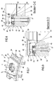
- Figure 2 shows an enlarged view of a portion of a combustor front assembly according to the prior art.
- the combustor front assembly comprises a combustor front plate 32 that is ring-shaped around the gas turbine axis.
- the combustor front plate 32 can be arranged orthogonal with respect to the gas turbine axis 4 or inclined as disclosed in figure 1 .
- the combustor front plate 32 comprises a plurality of through holes 21 equally spaced along the combustor front plate 32. These through holes 21 define a plurality of passages for the hot gas from the burners 11 to the annular combustion chamber 7.
- each through hole 21 of the front plate 32 is coupled with the relevant burner 11, preferably with the mixing tube in case of a EV burner.
- the combustor front assembly comprises a plurality of combustor front segments 22 that are tile-shaped and cover, on the burner 11 side, the entire length of the front plate 32.
- Each front segment 22 comprises a through hole 23 that, once the segment 22 is coupled with the plate 32, is axially aligned with the front plate through hole 21.
- the front segment 22 comprises a front wall 29 and side walls 30.
- Figure 3 is a schematic section view of the combustor front assembly of the figure 2 according to prior art along the section line A-A.
- the combustor front assembly comprises a hook member 24 having a base 25 housed in a relative seat 26 realized in the front plate 32 and a hook end 27 configured to be coupled with a through slot 28 realized in the lateral wall 20 of the front segment 22.
- the hook member 24 is fixed and pushed against the front plate 32 by a screw or bolt member 31 in order to maintain the front segment 22 in the correct position.
- a primary object of the present invention is to provide a combustor front assembly for a gas turbine that allows to increase the lifetime and the reliability of the fixation and sealing system between the combustor front plate and the combustor front segments.
- the present invention provides a combustor front assembly for a gas turbine wherein the gas turbine comprises:
- the combustion chamber comprising is an annular combustion chamber arranged concentrically to the turbine axis and comprises a combustor front assembly coupled with a plurality of burners, for instance EV-burners.
- the combustor front assembly is provided with at least a though hole (a plurality of though holes in case of an annular combustion chamber) in order to allow the gas flow to leave the burners and to enter the combustion chamber.
- the combustor front assembly comprises:
- the combustor front segment is clamped to the outer surface of the combustor front plate.
- the combustor front segment is kept in position in abutment against the front plate in a clamped manner.
- the combustor front assembly comprises a plurality of combustor front segments tile-shaped covering the entire outer surface of the combustor front plate.
- the fixation system of the present invention based on a clamping system between the front segment and the front plate, ensures robustness and reduces the risk of failure due front segment disengage during the start-up phase, the steady state operating regime and also after long operating periods.
- each tile-shaped combustor front segments comprises a front wall, spaced and parallel to the outer surface of the combustor front plate, and two opposite L-shaped side walls.
- Each L-shaped side wall comprises a first portion, orthogonal to the outer surface of the combustor front plate and connected with the front wall, and a second portion spaced and parallel to the front wall facing the outer surface of the combustor front plate. This second portion of the side walls of the combustor front segments is clamped and forced against to the outer surface of the combustor front plate.
- each tile-shaped combustor front segments comprises two side clamping strips having length equal to the side walls and are also configured to push the second portion of the side walls against the outer surface of the combustor front plate.
- the clamping and pushing effects are acting along the entire length of the side wall and therefore the contact pressure is distributed over a large area. Consequently, this solution allows to reduce the risk of wear along the side walls of the front segment.
- each tile-shaped combustor front segment comprises two side closing strips facing the side clamping strips and configured for clamping the free end of the second portion of the side walls between the side clamping strips and the side closing strips.
- each tile-shaped combustor front segment comprises an L-shaped outer and inner wall having a first portion, orthogonal to the outer surface of the combustor front plate and connected with the front wall, and a second portion spaced and parallel to the front wall.
- the second portion of such outer and inner wall of the combustor front segments are clamped and pushed against the outer surface of the combustor front plate.
- the clamping system of the present invention between the front segment and the front plate ensure sufficient robustness also along the inner and outer walls.
- each tile-shaped combustor front segment comprises an inner and an outer middle clamping plate arranged in the middle of the outer and inner wall.
- Such middle clamping plates are configured to clamp and push the second portion of the outer and inner wall against the outer surface of the combustor front plate.
- each tile-shaped combustor front segment comprises an inner and outer closing strip. Each closing strip is facing the relative middle clamping plate for clamping the free end of the second portion of the outer and inner wall between the middle clamping plates and the inner and outer closing strip.
- the clamping effect is acting along the entire length of the middle clamping plate and therefore the contact pressure is distributed over a large area. Consequently, this solution allows to reduce the risk of wear along the inner and an outer walls of the front segment.
- the middle clamping plates are also in abutment against a step seat realized in the inner surface of the through hole of the front segment.
- this solution allows to ensure the correct position of the middle clamping plates. Moreover, according to this feature, the front segment during the steady state operating condition is self-restraining due to its thermal deformation.
- the inner and outer closing strip and the side closing strips are integral each-others to form a single square frame.
- this solution allow to ensure an easy and quick assembly of the front segment.
- the combustor front assembly comprises a seal between the combustor front segment and the outer surface of the combustor front plate.
- the seal is a rope seal housed in a perimetric groove realized in the outer surface of the combustor front plate.
- this solution allow the seal to be clamped in position with limited movements. Consequently, the seal lifetime is optimized.
- the outer surface of the combustor front plate consists in straight portions.
- planar portions ensures to realize well-controlled clearances between the front plate and the front segments.
- FIG. 1 that is a schematic view of a gas turbine, will be made only in order to explain how the invention cooperates with the relative gas turbine.
- FIG 4 is a schematic partial prospective view of a front combustor assembly, on the burner side, according to the invention.
- the figure 4 discloses a portion of a ring-shaped combustor front plate 34 centered around the turbine axis 4 (see also figure 1 ) and a tile-shaped combustor front segments 38 coupled to the outer surface 36 of the combustor front plate 34.
- the outer surface 36 is the surface of the front plate 34 that is outside the combustion chamber 7 facing the burner 11 (see also figure 1 ).
- the combustor front plate 34 is provided with a plurality of through holes 35 equally spaced whereas each combustor front segment 38 comprises a through hole 39.
- the through hole 39 of the front segment 38 is aligned with the through hole 35 of the front plate 34 in order to realize a passage for the gas flowing from the burner 11 to the combustion chamber 7.
- the front segments 38 are arranged along the front plate 34 in order to cover the entire outer surface 36.
- the front plate 34 comprises fixing portions 55 configured to couple the front plate 34 to the inner 13 and outer shell 14 of the combustion chamber 7 (see also figure 1 ).
- Each tile-shaped combustor front segment 38 comprises a front wall 40, side walls 41, an inner and an outer wall 46.
- figure 5 is a schematic section view of the combustor front assembly of the figure 4 along the section line B-B.
- the front wall 40 of the front segments 38 is spaced and parallel with respect to the outer surface 36 of the front plate 34.
- the side walls 41 of the front segments 38 are L-shaped and comprise a first portion 42, orthogonal to the outer surface 36 of the combustor front plate 34, and a second portion 43, having a free end, spaced and parallel to the front wall 40.
- the second portion 43 of the side walls 41 of the combustor front segments 38 is facing the outer surface 36 of the front plate 34.
- the free end of such second portion 43 is clamped between the side clamping strip 44, in form of a rail parallel to the side wall 41, and the relative side closing strip 45.
- the side clamping strip 44 is coupled with the inner surface (inside the front segment 38) of the second portion 43 of the side wall 41 of the combustor front segments 38, whereas the side closing strip 45 is coupled to the outer surface (facing the front plate 34) of the second portion 43 of the side wall 41 of the combustor front segments 38.
- the side clamping strip 44 allows to clamp the free end of the second portions 43 and to push the second portion 43 against the outer surface 36 of the combustor front plate 34.
- the side closing strip 45 are arranged in a lowered portion 56 of the outer surface 36 of the combustor front plate 34 so that the main part of the second portion 43 of the side wall 41 is in abutment against a perimetric higher portion 57 of the outer surface 36 of the combustor front plate 34.
- Figure 5 discloses a seal 53 arranged in a groove 54 realized in the perimetric higher portion 57 of the outer surface 36 of the combustor front plate 34. In particular, the seal is between the outer surface 36 of the combustor front plate 34 and the second portions 43 of the side wall 41.
- the front segment 38 can be defined as clamped against the front plate 34 because the free ends of the side walls 41 of the front segment 38 are clamped and pressed against the outer surface 36, in particular against the perimetric higher portion 57.
- figure 6 is a schematic section view of the combustor front assembly of the figure 4 along the section line C-C.
- Figure 6 discloses that also the inner and outer wall 46 of the front segment 38 are L-shaped and comprise a first portion 47, orthogonal to the outer surface 36 of the combustor front plate 34 and connected with the front wall 40, and a second portion 48. Such second portion 48 is spaced and parallel to the front wall 40 facing the outer surface 36 of the front plate 34. As for the side walls 41, the free end of the second portion 38 of the outer and inner wall 46 is clamped between an inner and an outer middle clamping plate 49, arranged in the middle of the outer and inner wall 46, and an inner and outer closing strip 50.
- the middle clamping plate 49 proceed with clamping the free and of the second portion 48, and push the second portion 48 against the outer surface 36 of the combustor front plate 34.
- the middle clamping plate 49 is also resting on a step seat 52 realized in the inner surface of the hole 39.
- Figure 6 also discloses a seal 53 arranged in a groove 54 realized in the perimetric higher portion 57 of the outer surface 36 of the combustor front plate 34. The seal 53 is placed between the outer surface 36 of the combustor front plate 34 and the second portions 48 of the inner and outer wall 46.
- FIGS 7-9 are schematic view of the combustor front assembly of the figure 4 during the steady state operation regime of the relative gas turbine.
- figure 7 discloses the combustor front assembly of the figure 4 under the operation thermal deformation.
- figures 8 and 9 are schematic section views of the combustor front assembly of the figure 7 along the section lines C-C and D-D.
- the clamping system of the present invention is self-restraining. Indeed, along the line C-C, i.e. at the inner or outer wall 46, the thermal deformation acting on the side clamping strips 44 generates an additional pushing force located at the clamping zone and at the step seat 52.
- figure 10 is a schematic partial prospective view of the combustor front plate 34 of figure 4 without the front segment 38.
- figure 10 discloses the lower portion 56 and the higher portion 57 of the outer surface 36 of the combustor front plate 34. According to the invention, these portions 56 57 of the outer surface 36 of the combustor front plate 34 are straight. Between the lower portion 56 and the higher portion 57, the outer surface 36 of the combustor front plate 34 comprises a step that realizes a seat for the seal 53.
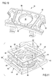
- figure 11 is a schematic exploded prospective view of the combustor front segment according to the invention.
- the inner and outer closing strip 50 and the side closing strips 45 are integral each-others to form a single square frame 51.
- such square frame 51 is fixed in position with respect to the middle clamping plates 49 and to the side clamping strips 44 by bolt or screw 60.
Abstract
- a combustor front plate having at least a through hole and provided with an outer surface outside the combustor chamber;
- at least a combustor front segment having a through hole and coupled with the outer surface of the combustor front plate so that the through hole of the front segment is aligned with the through hole of the front plate;
wherein
the combustor front segment is clamped in position and forced against the outer surface of the combustor front plate.
Description
- The present invention relates to a combustor front assembly for a gas turbine power plant.
- In particular, the present invention refers to an annular combustor front assembly suitable to be preferably associated with a plurality of EV burners.
- Moreover, the present invention refers to a gas turbine power plant provided with the above combustor front assembly.
- A gas turbine power plant (in the following only gas turbine) comprises, following the main gas flow, a compressor fed with air, one or more combustors fed with the compressed air wherein a fuel is injected, mixed to the air flow and burnt in order to generate an high pressure gas, and a turbine fed with the high pressure gas.
- In the case of the gas turbine is provided with an annular combustor, the combustion chamber is an annular structure around the gas turbine axis. This annular combustion chamber is outwardly and inwardly delimited by side walls, upstream by a front assembly coupled with a plurality of burners and downstream by a hot gas discharge passage facing the turbine.
- The terms outwardly/outer and inwardly/inner refer to the gas turbine axis. The terms upstream and downstream refer to the main gas flow direction.
- An example of this kind of gas turbine is schematically represented in
figure 1 wherein the reference M refers to the main gas flow direction. In particular, the gas turbine 1 comprises a casing 2 covering arotor 3 able to rotate around an axis 4. On the upstream side, the gas turbine 1 comprises acompressor 5 for compressing air that flows into a plenum 6. Inside the plenum 6, the gas turbine 1 comprises anannular combustion chamber 7 arranged concentrically to the axis 4 and provided with an inner 13 and anouter shell 14. On the inlet side, theannular combustion chamber 7 comprises acombustor front assembly 8 that is ring-shaped around the axis 4. On the outlet side, theannular combustion chamber 7 comprises a hot gas passage 9 connected with the inlet of theturbine 10.Figure 1 discloses aburner 11, in particular an EV-burner, coupled to thecombustor front assembly 8. Of course, along thecombustor front assembly 8 the gas turbine 1 comprises a plurality ofburner 11 equally spaced. The gas leaves the burner and enters theannular combustion chamber 7 passing thought thecombustor front assembly 8. Ahot air flow 12 formed during the combustion reaches theturbine 10 passing through the above mentioned hot gas passage 9 at the outlet side of theannular combustion chamber 7. Into theturbine 10 the hot air flow expands performing rotating work on the axis 4. Thecombustion chamber 7 is preferably enclosed by an outer 15 andinner cooling shroud 16 in order to realize an outer 17 andinner cooling passage 18. In thecooling passages 17 18, cooling air flows in the opposite direction with respect to thehot gas flow 12 along the walls of thecombustion chamber 7 into acombustor hood 19. From thecombustor hood 19 the air flows into theburner 11 or, passing thoughtfront cooling passages 20, directly into thecombustion chamber 7. - As foregoing described, the burner disclosed in
figure 1 is preferably a EV burner where EV stand for "environmental" burner. Alternatively, the burners can be AEV-burners where AEV stand for "Advanced EnVironmental". This kind of burners is characterized by a very low NOx levels. For instance,EP0851172 ,EP2423597 andWO 2009/019113 disclose EV burners provided with a single or double cone and comprising a swirl generator and a mixing tube at the exit of a burner prior the combustion chamber. The mixing tube is configured to stabilize the swirl flow. Preferably, between the swirl generator and the mixing tube an EV burner comprises also a transition piece. -
Figure 2 shows an enlarged view of a portion of a combustor front assembly according to the prior art. In particular. As known, the combustor front assembly comprises acombustor front plate 32 that is ring-shaped around the gas turbine axis. Thecombustor front plate 32 can be arranged orthogonal with respect to the gas turbine axis 4 or inclined as disclosed infigure 1 . Thecombustor front plate 32 comprises a plurality of throughholes 21 equally spaced along thecombustor front plate 32. These throughholes 21 define a plurality of passages for the hot gas from theburners 11 to theannular combustion chamber 7. In particular, each throughhole 21 of thefront plate 32 is coupled with therelevant burner 11, preferably with the mixing tube in case of a EV burner. As disclosed infigure 2 , on thefront plate 32 the combustor front assembly comprises a plurality of combustorfront segments 22 that are tile-shaped and cover, on theburner 11 side, the entire length of thefront plate 32. Eachfront segment 22 comprises a throughhole 23 that, once thesegment 22 is coupled with theplate 32, is axially aligned with the front plate throughhole 21. As disclosed infigure 2 , thefront segment 22 comprises afront wall 29 andside walls 30. -
Figure 3 is a schematic section view of the combustor front assembly of thefigure 2 according to prior art along the section line A-A. In particular,figure 3 shows how thefront segment 22 is coupled with thefront plate 32 according the prior art. According to this embodiment, the combustor front assembly comprises ahook member 24 having abase 25 housed in arelative seat 26 realized in thefront plate 32 and ahook end 27 configured to be coupled with a throughslot 28 realized in thelateral wall 20 of thefront segment 22. Thehook member 24 is fixed and pushed against thefront plate 32 by a screw orbolt member 31 in order to maintain thefront segment 22 in the correct position. - However, the
combustor front segment 22 are exposed to high level of vibrations and thermal deformation and, unfortunately, the foregoing described hook fixing system solution of the prior art is subject to frequent failure due to the high contact wear which leads often to disengage thefront segments 22 from thecombustor plate 32. - Accordingly, a primary object of the present invention is to provide a combustor front assembly for a gas turbine that allows to increase the lifetime and the reliability of the fixation and sealing system between the combustor front plate and the combustor front segments.
- In order to achieve the objective mentioned above, the present invention provides a combustor front assembly for a gas turbine wherein the gas turbine comprises:
- a rotor rotating around an axis;
- a compressor upstream coupled to the rotor for compressing air;
- a combustion chamber wherein the compressed air is mixed with fuel and burnt in order to generate an high pressure gas;
- a turbine downstream coupled to the rotor wherein the high pressure gas expands performing rotating work on the axis.
- Preferably, the combustion chamber comprising is an annular combustion chamber arranged concentrically to the turbine axis and comprises a combustor front assembly coupled with a plurality of burners, for instance EV-burners.
- The combustor front assembly is provided with at least a though hole (a plurality of though holes in case of an annular combustion chamber) in order to allow the gas flow to leave the burners and to enter the combustion chamber. In particular, the combustor front assembly comprises:
- a combustor front plate having at least a through hole and provided with an outer surface outside the combustor chamber;
- at least a combustor front segment having a through hole and coupled to the outer surface of the combustor front plate so that the through hole of the front segment is aligned with the through hole of the front plate.
- According to the invention, the combustor front segment is clamped to the outer surface of the combustor front plate. In other words, according to the invention the combustor front segment is kept in position in abutment against the front plate in a clamped manner.
- In case of an annular combustor, the combustor front assembly comprises a plurality of combustor front segments tile-shaped covering the entire outer surface of the combustor front plate.
- Advantageously, the fixation system of the present invention, based on a clamping system between the front segment and the front plate, ensures robustness and reduces the risk of failure due front segment disengage during the start-up phase, the steady state operating regime and also after long operating periods.
- In particular, each tile-shaped combustor front segments comprises a front wall, spaced and parallel to the outer surface of the combustor front plate, and two opposite L-shaped side walls. Each L-shaped side wall comprises a first portion, orthogonal to the outer surface of the combustor front plate and connected with the front wall, and a second portion spaced and parallel to the front wall facing the outer surface of the combustor front plate. This second portion of the side walls of the combustor front segments is clamped and forced against to the outer surface of the combustor front plate.
- In particular, each tile-shaped combustor front segments comprises two side clamping strips having length equal to the side walls and are also configured to push the second portion of the side walls against the outer surface of the combustor front plate.
- Advantageously, the clamping and pushing effects are acting along the entire length of the side wall and therefore the contact pressure is distributed over a large area. Consequently, this solution allows to reduce the risk of wear along the side walls of the front segment.
- In particular, each tile-shaped combustor front segment comprises two side closing strips facing the side clamping strips and configured for clamping the free end of the second portion of the side walls between the side clamping strips and the side closing strips.
- In particular, each tile-shaped combustor front segment comprises an L-shaped outer and inner wall having a first portion, orthogonal to the outer surface of the combustor front plate and connected with the front wall, and a second portion spaced and parallel to the front wall. The second portion of such outer and inner wall of the combustor front segments are clamped and pushed against the outer surface of the combustor front plate.
- Advantageously, the clamping system of the present invention between the front segment and the front plate, ensure sufficient robustness also along the inner and outer walls.
- In particular, each tile-shaped combustor front segment comprises an inner and an outer middle clamping plate arranged in the middle of the outer and inner wall. Such middle clamping plates are configured to clamp and push the second portion of the outer and inner wall against the outer surface of the combustor front plate. Also along the outer and inner wall each tile-shaped combustor front segment comprises an inner and outer closing strip. Each closing strip is facing the relative middle clamping plate for clamping the free end of the second portion of the outer and inner wall between the middle clamping plates and the inner and outer closing strip.
- Advantageously, the clamping effect is acting along the entire length of the middle clamping plate and therefore the contact pressure is distributed over a large area. Consequently, this solution allows to reduce the risk of wear along the inner and an outer walls of the front segment.
- In particular, the middle clamping plates are also in abutment against a step seat realized in the inner surface of the through hole of the front segment.
- Advantageously, this solution allows to ensure the correct position of the middle clamping plates. Moreover, according to this feature, the front segment during the steady state operating condition is self-restraining due to its thermal deformation.
- In particular, the inner and outer closing strip and the side closing strips are integral each-others to form a single square frame.
- Advantageously, this solution allow to ensure an easy and quick assembly of the front segment.
- In particular, the combustor front assembly comprises a seal between the combustor front segment and the outer surface of the combustor front plate. Preferably, the seal is a rope seal housed in a perimetric groove realized in the outer surface of the combustor front plate.
- Advantageously, this solution allow the seal to be clamped in position with limited movements. Consequently, the seal lifetime is optimized.
- In particular, the outer surface of the combustor front plate consists in straight portions.
- Advantageously, such planar portions ensures to realize well-controlled clearances between the front plate and the front segments.
- It is to be understood that both the foregoing general description and the following detailed description are exemplary, and are intended to provide further explanation of the invention as claimed. Other advantages and features of the invention will be apparent from the following description, drawings and claims.
- The features of the invention believed to be novel are set forth with particularity in the appended claims.
- Further benefits and advantages of the present invention will become apparent after a careful reading of the detailed description with appropriate reference to the accompanying drawings.
- The invention itself, however, may be best understood by reference to the following detailed description of the invention, which describes an exemplary embodiment of the invention, taken in conjunction with the accompanying drawings, in which:
-
Figure 1 is a schematic section view of a gas turbine provided with an annular combustion chamber; -
Figure 2 is a schematic partial prospective view of a front combustor assembly according to the prior art; -
Figure 3 is a schematic section view of the combustor front assembly of thefigure 2 along the section line A-A; -
Figure 4 is a schematic partial prospective view of a front combustor assembly according to the invention; -
Figure 5 is a schematic section view of the combustor front assembly of thefigure 4 along the section line B-B; -
Figure 6 is a schematic section view of the combustor front assembly of thefigure 4 along the section line C-C; -
Figure 7 is a schematic partial prospective view of the combustor front assembly of thefigure 4 under thermal deformation during the steady state operation regime of the relative gas turbine; -
Figure 8 is a schematic section view of the combustor front assembly of thefigure 7 along the section line C-C; -
Figure 9 is a schematic section view of the combustor front assembly of thefigure 7 along the section line D-D; -
Figure 10 is a schematic partial prospective view of the combustor front plate without any front segment according to the invention; and -
Figure 11 is a schematic exploded prospective view of the combustor front segment according to the invention. - In cooperation with attached drawings, the technical content and the detailed description of the present invention are described thereinafter according to preferable embodiments, being not used to limit its executing scope. Any equivalent variation and modification made according to appended claims is all covered by the claims claimed by the present invention.
- In particular, reference will be made to the
figures 4-11 that disclose in detail an embodiment of the present invention. Reference tofigure 1 , that is a schematic view of a gas turbine, will be made only in order to explain how the invention cooperates with the relative gas turbine. - Reference in now made to the
figure 4 that is a schematic partial prospective view of a front combustor assembly, on the burner side, according to the invention. - In particular, the
figure 4 discloses a portion of a ring-shapedcombustor front plate 34 centered around the turbine axis 4 (see alsofigure 1 ) and a tile-shapedcombustor front segments 38 coupled to theouter surface 36 of the combustorfront plate 34. Theouter surface 36 is the surface of thefront plate 34 that is outside thecombustion chamber 7 facing the burner 11 (see alsofigure 1 ). - According to
figure 4 , the combustorfront plate 34 is provided with a plurality of throughholes 35 equally spaced whereas eachcombustor front segment 38 comprises a throughhole 39. Once thecombustor front segment 38 is coupled to theouter surface 36 of the combustorfront plate 34, the throughhole 39 of thefront segment 38 is aligned with the throughhole 35 of thefront plate 34 in order to realize a passage for the gas flowing from theburner 11 to thecombustion chamber 7. Thefront segments 38 are arranged along thefront plate 34 in order to cover the entireouter surface 36. - According to
figure 4 , thefront plate 34 comprises fixingportions 55 configured to couple thefront plate 34 to the inner 13 andouter shell 14 of the combustion chamber 7 (see alsofigure 1 ). Each tile-shapedcombustor front segment 38 comprises afront wall 40,side walls 41, an inner and anouter wall 46. - Reference is now made to
figure 5 that is a schematic section view of the combustor front assembly of thefigure 4 along the section line B-B. - According to
figure 5 , thefront wall 40 of thefront segments 38 is spaced and parallel with respect to theouter surface 36 of thefront plate 34. Theside walls 41 of thefront segments 38 are L-shaped and comprise afirst portion 42, orthogonal to theouter surface 36 of the combustorfront plate 34, and asecond portion 43, having a free end, spaced and parallel to thefront wall 40. Thesecond portion 43 of theside walls 41 of the combustorfront segments 38 is facing theouter surface 36 of thefront plate 34. The free end of suchsecond portion 43 is clamped between theside clamping strip 44, in form of a rail parallel to theside wall 41, and the relativeside closing strip 45. Respectively, theside clamping strip 44 is coupled with the inner surface (inside the front segment 38) of thesecond portion 43 of theside wall 41 of the combustorfront segments 38, whereas theside closing strip 45 is coupled to the outer surface (facing the front plate 34) of thesecond portion 43 of theside wall 41 of the combustorfront segments 38. By acting on a screw orbolt member 31 passing thefront plate 34 and the side clamping strip 44 (seefigure 5 ), theside clamping strip 44 allows to clamp the free end of thesecond portions 43 and to push thesecond portion 43 against theouter surface 36 of the combustorfront plate 34. Indeed, as disclosed infigure 5 , theside closing strip 45 are arranged in a loweredportion 56 of theouter surface 36 of the combustorfront plate 34 so that the main part of thesecond portion 43 of theside wall 41 is in abutment against a perimetrichigher portion 57 of theouter surface 36 of the combustorfront plate 34.Figure 5 discloses aseal 53 arranged in a groove 54 realized in the perimetrichigher portion 57 of theouter surface 36 of the combustorfront plate 34. In particular, the seal is between theouter surface 36 of the combustorfront plate 34 and thesecond portions 43 of theside wall 41. - In view of the foregoing description, the
front segment 38 can be defined as clamped against thefront plate 34 because the free ends of theside walls 41 of thefront segment 38 are clamped and pressed against theouter surface 36, in particular against the perimetrichigher portion 57. - Reference is now made to
figure 6 that is a schematic section view of the combustor front assembly of thefigure 4 along the section line C-C. -
Figure 6 discloses that also the inner andouter wall 46 of thefront segment 38 are L-shaped and comprise afirst portion 47, orthogonal to theouter surface 36 of the combustorfront plate 34 and connected with thefront wall 40, and asecond portion 48. Suchsecond portion 48 is spaced and parallel to thefront wall 40 facing theouter surface 36 of thefront plate 34.
As for theside walls 41, the free end of thesecond portion 38 of the outer andinner wall 46 is clamped between an inner and an outermiddle clamping plate 49, arranged in the middle of the outer andinner wall 46, and an inner andouter closing strip 50. Acting on a screw orbolt member 31 passing thefront plate 34 and the middle clamping plate 49 (seefigure 6 ), themiddle clamping plate 49 proceed with clamping the free and of thesecond portion 48, and push thesecond portion 48 against theouter surface 36 of the combustorfront plate 34. According tofigure 6 , themiddle clamping plate 49 is also resting on astep seat 52 realized in the inner surface of thehole 39.Figure 6 also discloses aseal 53 arranged in a groove 54 realized in the perimetrichigher portion 57 of theouter surface 36 of the combustorfront plate 34. Theseal 53 is placed between theouter surface 36 of the combustorfront plate 34 and thesecond portions 48 of the inner andouter wall 46. - Reference is now made to
figures 7-9 that are schematic view of the combustor front assembly of thefigure 4 during the steady state operation regime of the relative gas turbine. In other words,figure 7 discloses the combustor front assembly of thefigure 4 under the operation thermal deformation. In particular,figures 8 and 9 are schematic section views of the combustor front assembly of thefigure 7 along the section lines C-C and D-D. These figures disclose that the clamping system of the present invention is self-restraining. Indeed, along the line C-C, i.e. at the inner orouter wall 46, the thermal deformation acting on the side clamping strips 44 generates an additional pushing force located at the clamping zone and at thestep seat 52. - Along the line D-D, i.e. at the corner of the
front segment 38, the thermal deformation generates an additional pushing force acting at thefront segment 38 against thefront plate 34. Infigure 8 and 9 the location where these additional pushing forces are acting have been schematically represented by thereference number 58. The dottedline 59 above thefront wall 40 schematically represents the deformation of thefront segment 38 during the steady state operation regime of the gas turbine. - Reference is now made to
figure 10 that is a schematic partial prospective view of the combustorfront plate 34 offigure 4 without thefront segment 38. In particular,figure 10 discloses thelower portion 56 and thehigher portion 57 of theouter surface 36 of the combustorfront plate 34. According to the invention, theseportions 56 57 of theouter surface 36 of the combustorfront plate 34 are straight. Between thelower portion 56 and thehigher portion 57, theouter surface 36 of the combustorfront plate 34 comprises a step that realizes a seat for theseal 53. - Reference is now made to
figure 11 that is a schematic exploded prospective view of the combustor front segment according to the invention. According to this embodiment, the inner andouter closing strip 50 and the side closing strips 45 are integral each-others to form a singlesquare frame 51. According tofigure 11 , suchsquare frame 51 is fixed in position with respect to themiddle clamping plates 49 and to the side clamping strips 44 by bolt orscrew 60. - Although the invention has been explained in relation to its preferred embodiment(s) as mentioned above, it is to be understood that many other possible modifications and variations can be made without departing from the scope of the present invention. It is, therefore, contemplated that the appended claim or claims will cover such modifications and variations that fall within the true scope of the invention.
Claims (15)
- Combustor front assembly for a gas turbine power plant (1), wherein the combustor front assembly (8) is provided with at least a through hole (33) for allowing the gas flow to come into a combustion chamber (7), the combustor front assembly (8) comprising:- a combustor front plate (34) having at least a through hole (35) and provided with an outer surface (36) outside the combustor chamber (7);- at least a combustor front segment (38) having a through hole (39) and coupled with the outer surface (36) of the combustor front plate (34) so that the through hole (39) of the front segment (38) is aligned with the through hole (35) of the front plate (34);
characterized in that
the combustor front segment (38) is clamped in position and forced against the outer surface (36) of the combustor front plate (34). - Combustor front assembly as claimed in claim 1, wherein the gas turbine (1) comprises a rotor (3) having an axis (4) and the combustor front plate (34) is ring-shaped around the axis (4); the combustor front plate (34) is provided with a plurality of through holes (35) equally spaced along the front plate (34); the combustor front assembly (8) comprising a plurality of combustor front segments (38) tile-shaped covering the entire outer surface (36) of the combustor front plate (34).
- Combustor front assembly as claimed in claim 2, wherein each combustor front segments (38) comprises a front wall (40) spaced and parallel to the outer surface (36) of the combustor front plate (34), two opposite side walls (41) L-shaped having a first portion (42), orthogonal to the outer surface (36) of the combustor front plate (34) and connected with the front wall (40), and a second portion (43) spaced and parallel to the front wall (40); the second portion (43) of the side walls (41) of the combustor front segments (38) being clamped and pushed against the outer surface (36) of the combustor front plate (34).
- Combustor front assembly as claimed in claim 3, wherein each combustor front segment (38) comprises two side clamping strips (44) having length equal to the side walls (41) acting on the second portion (43) of the side walls (41) inside the combustor front segments (38).
- Combustor front assembly as claimed in claim 4, wherein each combustor front segment (38) comprises two side closing strips (45) facing the side clamping strips (44) for clamping the free end of the second portion (43) of the side walls (41) between the side clamping strips (44) and the side closing strips (45).
- Combustor front assembly as claimed in any foregoing claims, wherein each combustor front segment (38) comprises a front wall (40) spaced and parallel to the outer surface (36) of the combustor front plate (34), an outer and an inner wall (46) L-shaped having a first portion (47), orthogonal to the outer surface (36) of the combustor front plate (34) and connected with the front wall (40), and a second portion (48) spaced and parallel to the front wall (40); the second portion (48) of outer and inner wall (46) of the combustor front segment (38) being clamped and pushed against the outer surface (36) of the combustor front plate (34) .
- Combustor front assembly as claimed in claim 6, wherein each combustor front segment (38) comprises an inner and an outer clamping plate (49) arranged in the middle of the outer and inner wall (46) acting on the second portion (48) of the outer and inner wall (46) inside the combustor front segments (38).
- Combustor front assembly as claimed in claim 7, wherein each combustor front segments (38) comprises an inner and outer closing strip (50) facing the inner and an outer clamping plate (49) for clamping the free end of the second portions (48) of the outer and inner wall (46) between the clamping plates (49) and the inner and outer closing strip (50) .
- Combustor front assembly as claimed in claim 8, wherein the clamping plates (49) are in abutment against a step seat (52) realized in the inner surface of the hole (39)
- Combustor front assembly as claimed in claim 8 o 9, wherein the inner and outer closing strip (50) and the side closing strips (45) are integral each-others to form a single square frame (51).
- Combustor front assembly as claimed in any foregoing claims, wherein it comprises a seal (53) between the combustor front segment (38) and the outer surface (36) of the combustor front plate (34).
- Combustor front assembly as claimed in claim 11, wherein the seal is a rope seal (53) housed in a perimetric groove (54) realized in the outer surface (36) of the combustor front plate (34).
- Combustor front assembly as claimed in claim 11, wherein the outer surface (36) of the combustor front plate (34) consists in straight portions.
- Gas turbine power plant (1) comprising- a rotor (3) rotating around an axis (4);- a compressor (5) upstream coupled to the rotor (3) for compressing air;- an annular combustion chamber (7) wherein the compressed air is mixed with fuel and burnt in order to generate an high pressure gas;- a turbine (10) downstream coupled to the rotor (3) wherein the high pressure gas expands performing work on the rotor (3) ;
the annular combustion chamber (7) being arranged concentrically to the axis (4) and comprising a combustor front assembly (8) coupled with a plurality of burners (11); characterized in that
the combustor front assembly (8) is realized according to any foregoing claims. - Gas turbine power plant as claimed in claim 14, wherein the burners (11) are EV-burners or AEV-burners.
Priority Applications (3)
| Application Number | Priority Date | Filing Date | Title |
|---|---|---|---|
| EP16190197.0A EP3299720B1 (en) | 2016-09-22 | 2016-09-22 | Combustor front assembly for a gas turbine |
| US15/708,696 US20180080651A1 (en) | 2016-09-22 | 2017-09-19 | Combustor front assembly for a gas turbine |
| CN201710866282.7A CN107869735B (en) | 2016-09-22 | 2017-09-22 | Combustor front assembly for a gas turbine |
Applications Claiming Priority (1)
| Application Number | Priority Date | Filing Date | Title |
|---|---|---|---|
| EP16190197.0A EP3299720B1 (en) | 2016-09-22 | 2016-09-22 | Combustor front assembly for a gas turbine |
Publications (2)
| Publication Number | Publication Date |
|---|---|
| EP3299720A1 true EP3299720A1 (en) | 2018-03-28 |
| EP3299720B1 EP3299720B1 (en) | 2020-11-04 |
Family
ID=56985547
Family Applications (1)
| Application Number | Title | Priority Date | Filing Date |
|---|---|---|---|
| EP16190197.0A Active EP3299720B1 (en) | 2016-09-22 | 2016-09-22 | Combustor front assembly for a gas turbine |
Country Status (3)
| Country | Link |
|---|---|
| US (1) | US20180080651A1 (en) |
| EP (1) | EP3299720B1 (en) |
| CN (1) | CN107869735B (en) |
Cited By (1)
| Publication number | Priority date | Publication date | Assignee | Title |
|---|---|---|---|---|
| CN111520761A (en) * | 2020-04-22 | 2020-08-11 | 中国空气动力研究与发展中心 | Rotary detonation combustion chamber capable of realizing observation of flow field structure of isolation section |
Citations (7)
| Publication number | Priority date | Publication date | Assignee | Title |
|---|---|---|---|---|
| US5291733A (en) * | 1993-02-08 | 1994-03-08 | General Electric Company | Liner mounting assembly |
| EP0716267A2 (en) * | 1994-12-08 | 1996-06-12 | ROLLS-ROYCE plc | Combustor assembly |
| EP0851172A2 (en) | 1996-12-23 | 1998-07-01 | Abb Research Ltd. | Burner for operating a combustion chamber with a liquid and/or gaseous fuel |
| US20040103668A1 (en) * | 2002-12-03 | 2004-06-03 | Bibler John D. | Method and apparatus to decrease gas turbine engine combustor emissions |
| WO2009019113A2 (en) | 2007-08-07 | 2009-02-12 | Alstom Technology Ltd | Burner for a combustion chamber of a turbo group |
| EP2423597A2 (en) | 2010-08-27 | 2012-02-29 | Alstom Technology Ltd | Premix burner for a gas turbine |
| EP2463583A1 (en) * | 2010-12-06 | 2012-06-13 | Alstom Technology Ltd | Gas turbine and method for reconditioning such a gas turbine |
Family Cites Families (4)
| Publication number | Priority date | Publication date | Assignee | Title |
|---|---|---|---|---|
| EP1302723A1 (en) * | 2001-10-15 | 2003-04-16 | Siemens Aktiengesellschaft | Lining for combustion chamber inside walls |
| EP2685160B1 (en) * | 2012-07-10 | 2018-02-21 | Ansaldo Energia Switzerland AG | Premix burner of the multi-cone type for a gas turbine |
| EP2952812B1 (en) * | 2014-06-05 | 2018-08-08 | General Electric Technology GmbH | Annular combustion chamber of a gas turbine and liner segment |
| US9840932B2 (en) * | 2014-10-06 | 2017-12-12 | General Electric Company | System and method for blade tip clearance control |
-
2016
- 2016-09-22 EP EP16190197.0A patent/EP3299720B1/en active Active
-
2017
- 2017-09-19 US US15/708,696 patent/US20180080651A1/en not_active Abandoned
- 2017-09-22 CN CN201710866282.7A patent/CN107869735B/en active Active
Patent Citations (7)
| Publication number | Priority date | Publication date | Assignee | Title |
|---|---|---|---|---|
| US5291733A (en) * | 1993-02-08 | 1994-03-08 | General Electric Company | Liner mounting assembly |
| EP0716267A2 (en) * | 1994-12-08 | 1996-06-12 | ROLLS-ROYCE plc | Combustor assembly |
| EP0851172A2 (en) | 1996-12-23 | 1998-07-01 | Abb Research Ltd. | Burner for operating a combustion chamber with a liquid and/or gaseous fuel |
| US20040103668A1 (en) * | 2002-12-03 | 2004-06-03 | Bibler John D. | Method and apparatus to decrease gas turbine engine combustor emissions |
| WO2009019113A2 (en) | 2007-08-07 | 2009-02-12 | Alstom Technology Ltd | Burner for a combustion chamber of a turbo group |
| EP2423597A2 (en) | 2010-08-27 | 2012-02-29 | Alstom Technology Ltd | Premix burner for a gas turbine |
| EP2463583A1 (en) * | 2010-12-06 | 2012-06-13 | Alstom Technology Ltd | Gas turbine and method for reconditioning such a gas turbine |
Cited By (2)
| Publication number | Priority date | Publication date | Assignee | Title |
|---|---|---|---|---|
| CN111520761A (en) * | 2020-04-22 | 2020-08-11 | 中国空气动力研究与发展中心 | Rotary detonation combustion chamber capable of realizing observation of flow field structure of isolation section |
| CN111520761B (en) * | 2020-04-22 | 2022-02-01 | 中国空气动力研究与发展中心 | Rotary detonation combustion chamber capable of realizing observation of flow field structure of isolation section |
Also Published As
| Publication number | Publication date |
|---|---|
| EP3299720B1 (en) | 2020-11-04 |
| CN107869735B (en) | 2021-12-14 |
| CN107869735A (en) | 2018-04-03 |
| US20180080651A1 (en) | 2018-03-22 |
Similar Documents
| Publication | Publication Date | Title |
|---|---|---|
| US9322556B2 (en) | Flow sleeve assembly for a combustion module of a gas turbine combustor | |
| EP2710230B1 (en) | Turbine combustion system transition piece side seals | |
| US20090166988A1 (en) | Gas turbine with a gap blocking device | |
| JP2017524089A (en) | Shroud hanger assembly | |
| RU2541482C2 (en) | Burner and gas turbine with such burner | |
| EP2837889A1 (en) | Sequential combustion with dilution gas mixer | |
| EP3450851B1 (en) | Transition duct for a gas turbine can combustor and gas turbine comprising such a transition duct | |
| KR20190032846A (en) | Structure for supporting turbine, turbine and gas turbine using the same | |
| JP2017166811A (en) | Axially staged fuel injector assembly mounting | |
| EP3412972B1 (en) | Gas turbine comprising a plurality of can-combustors | |
| KR101985109B1 (en) | First stage turbine vane support structure and gas turbine including the same | |
| RU2726139C1 (en) | Combustion chamber of gas turbine and transition compartment assembly | |
| CA2936200C (en) | Combustor cooling system | |
| JP2018155246A (en) | Gas turbine, guide blade ring of gas turbine, and method for producing guide blade ring | |
| EP3299720B1 (en) | Combustor front assembly for a gas turbine | |
| US20160033134A1 (en) | Seal in combustor nozzle of gas turbine engine | |
| US10151250B2 (en) | Method of operating a gas turbine assembly and the gas turbine assembly | |
| EP3845810B1 (en) | Supporting device for a heat-insulating tiles of a combustion chamber of a gas turbine assembly for power plants and a gas turbine assembly | |
| US10371385B2 (en) | Sequential burner for an axial gas turbine | |
| KR102205571B1 (en) | Fixing and sealing structure between turbine blade and turbine rotor disk | |
| WO2010046167A1 (en) | Gas turbine nozzle arrangement and gas turbine | |
| KR102059187B1 (en) | Pre-swirl system and gas turbine including the same | |
| EP2685052A1 (en) | A heat shield and a method for construction thereof | |
| KR102021046B1 (en) | Supporting structure of combustion duct for gas turbine engine | |
| EP3945246A1 (en) | Gas turbine assembly for power plants having an improved honeycomb seal device for sealing the combustor to turbine interface |
Legal Events
| Date | Code | Title | Description |
|---|---|---|---|
| PUAI | Public reference made under article 153(3) epc to a published international application that has entered the european phase |
Free format text: ORIGINAL CODE: 0009012 |
|
| STAA | Information on the status of an ep patent application or granted ep patent |
Free format text: STATUS: THE APPLICATION HAS BEEN PUBLISHED |
|
| AK | Designated contracting states |
Kind code of ref document: A1 Designated state(s): AL AT BE BG CH CY CZ DE DK EE ES FI FR GB GR HR HU IE IS IT LI LT LU LV MC MK MT NL NO PL PT RO RS SE SI SK SM TR |
|
| AX | Request for extension of the european patent |
Extension state: BA ME |
|
| STAA | Information on the status of an ep patent application or granted ep patent |
Free format text: STATUS: REQUEST FOR EXAMINATION WAS MADE |
|
| 17P | Request for examination filed |
Effective date: 20180926 |
|
| RBV | Designated contracting states (corrected) |
Designated state(s): AL AT BE BG CH CY CZ DE DK EE ES FI FR GB GR HR HU IE IS IT LI LT LU LV MC MK MT NL NO PL PT RO RS SE SI SK SM TR |
|
| GRAP | Despatch of communication of intention to grant a patent |
Free format text: ORIGINAL CODE: EPIDOSNIGR1 |
|
| STAA | Information on the status of an ep patent application or granted ep patent |
Free format text: STATUS: GRANT OF PATENT IS INTENDED |
|
| INTG | Intention to grant announced |
Effective date: 20200417 |
|
| GRAS | Grant fee paid |
Free format text: ORIGINAL CODE: EPIDOSNIGR3 |
|
| GRAA | (expected) grant |
Free format text: ORIGINAL CODE: 0009210 |
|
| STAA | Information on the status of an ep patent application or granted ep patent |
Free format text: STATUS: THE PATENT HAS BEEN GRANTED |
|
| AK | Designated contracting states |
Kind code of ref document: B1 Designated state(s): AL AT BE BG CH CY CZ DE DK EE ES FI FR GB GR HR HU IE IS IT LI LT LU LV MC MK MT NL NO PL PT RO RS SE SI SK SM TR |
|
| REG | Reference to a national code |
Ref country code: GB Ref legal event code: FG4D |
|
| REG | Reference to a national code |
Ref country code: CH Ref legal event code: EP |
|
| REG | Reference to a national code |
Ref country code: AT Ref legal event code: REF Ref document number: 1331318 Country of ref document: AT Kind code of ref document: T Effective date: 20201115 |
|
| REG | Reference to a national code |
Ref country code: DE Ref legal event code: R096 Ref document number: 602016047038 Country of ref document: DE |
|
| REG | Reference to a national code |
Ref country code: IE Ref legal event code: FG4D |
|
| REG | Reference to a national code |
Ref country code: NL Ref legal event code: MP Effective date: 20201104 |
|
| REG | Reference to a national code |
Ref country code: AT Ref legal event code: MK05 Ref document number: 1331318 Country of ref document: AT Kind code of ref document: T Effective date: 20201104 |
|
| PG25 | Lapsed in a contracting state [announced via postgrant information from national office to epo] |
Ref country code: RS Free format text: LAPSE BECAUSE OF FAILURE TO SUBMIT A TRANSLATION OF THE DESCRIPTION OR TO PAY THE FEE WITHIN THE PRESCRIBED TIME-LIMIT Effective date: 20201104 Ref country code: PT Free format text: LAPSE BECAUSE OF FAILURE TO SUBMIT A TRANSLATION OF THE DESCRIPTION OR TO PAY THE FEE WITHIN THE PRESCRIBED TIME-LIMIT Effective date: 20210304 Ref country code: NO Free format text: LAPSE BECAUSE OF FAILURE TO SUBMIT A TRANSLATION OF THE DESCRIPTION OR TO PAY THE FEE WITHIN THE PRESCRIBED TIME-LIMIT Effective date: 20210204 Ref country code: FI Free format text: LAPSE BECAUSE OF FAILURE TO SUBMIT A TRANSLATION OF THE DESCRIPTION OR TO PAY THE FEE WITHIN THE PRESCRIBED TIME-LIMIT Effective date: 20201104 Ref country code: GR Free format text: LAPSE BECAUSE OF FAILURE TO SUBMIT A TRANSLATION OF THE DESCRIPTION OR TO PAY THE FEE WITHIN THE PRESCRIBED TIME-LIMIT Effective date: 20210205 |
|
| PG25 | Lapsed in a contracting state [announced via postgrant information from national office to epo] |
Ref country code: SE Free format text: LAPSE BECAUSE OF FAILURE TO SUBMIT A TRANSLATION OF THE DESCRIPTION OR TO PAY THE FEE WITHIN THE PRESCRIBED TIME-LIMIT Effective date: 20201104 Ref country code: AT Free format text: LAPSE BECAUSE OF FAILURE TO SUBMIT A TRANSLATION OF THE DESCRIPTION OR TO PAY THE FEE WITHIN THE PRESCRIBED TIME-LIMIT Effective date: 20201104 Ref country code: ES Free format text: LAPSE BECAUSE OF FAILURE TO SUBMIT A TRANSLATION OF THE DESCRIPTION OR TO PAY THE FEE WITHIN THE PRESCRIBED TIME-LIMIT Effective date: 20201104 Ref country code: BG Free format text: LAPSE BECAUSE OF FAILURE TO SUBMIT A TRANSLATION OF THE DESCRIPTION OR TO PAY THE FEE WITHIN THE PRESCRIBED TIME-LIMIT Effective date: 20210204 Ref country code: LV Free format text: LAPSE BECAUSE OF FAILURE TO SUBMIT A TRANSLATION OF THE DESCRIPTION OR TO PAY THE FEE WITHIN THE PRESCRIBED TIME-LIMIT Effective date: 20201104 Ref country code: IS Free format text: LAPSE BECAUSE OF FAILURE TO SUBMIT A TRANSLATION OF THE DESCRIPTION OR TO PAY THE FEE WITHIN THE PRESCRIBED TIME-LIMIT Effective date: 20210304 Ref country code: PL Free format text: LAPSE BECAUSE OF FAILURE TO SUBMIT A TRANSLATION OF THE DESCRIPTION OR TO PAY THE FEE WITHIN THE PRESCRIBED TIME-LIMIT Effective date: 20201104 |
|
| REG | Reference to a national code |
Ref country code: LT Ref legal event code: MG9D |
|
| PG25 | Lapsed in a contracting state [announced via postgrant information from national office to epo] |
Ref country code: HR Free format text: LAPSE BECAUSE OF FAILURE TO SUBMIT A TRANSLATION OF THE DESCRIPTION OR TO PAY THE FEE WITHIN THE PRESCRIBED TIME-LIMIT Effective date: 20201104 |
|
| PG25 | Lapsed in a contracting state [announced via postgrant information from national office to epo] |
Ref country code: RO Free format text: LAPSE BECAUSE OF FAILURE TO SUBMIT A TRANSLATION OF THE DESCRIPTION OR TO PAY THE FEE WITHIN THE PRESCRIBED TIME-LIMIT Effective date: 20201104 Ref country code: SK Free format text: LAPSE BECAUSE OF FAILURE TO SUBMIT A TRANSLATION OF THE DESCRIPTION OR TO PAY THE FEE WITHIN THE PRESCRIBED TIME-LIMIT Effective date: 20201104 Ref country code: SM Free format text: LAPSE BECAUSE OF FAILURE TO SUBMIT A TRANSLATION OF THE DESCRIPTION OR TO PAY THE FEE WITHIN THE PRESCRIBED TIME-LIMIT Effective date: 20201104 Ref country code: LT Free format text: LAPSE BECAUSE OF FAILURE TO SUBMIT A TRANSLATION OF THE DESCRIPTION OR TO PAY THE FEE WITHIN THE PRESCRIBED TIME-LIMIT Effective date: 20201104 Ref country code: CZ Free format text: LAPSE BECAUSE OF FAILURE TO SUBMIT A TRANSLATION OF THE DESCRIPTION OR TO PAY THE FEE WITHIN THE PRESCRIBED TIME-LIMIT Effective date: 20201104 Ref country code: EE Free format text: LAPSE BECAUSE OF FAILURE TO SUBMIT A TRANSLATION OF THE DESCRIPTION OR TO PAY THE FEE WITHIN THE PRESCRIBED TIME-LIMIT Effective date: 20201104 |
|
| REG | Reference to a national code |
Ref country code: DE Ref legal event code: R097 Ref document number: 602016047038 Country of ref document: DE |
|
| PG25 | Lapsed in a contracting state [announced via postgrant information from national office to epo] |
Ref country code: DK Free format text: LAPSE BECAUSE OF FAILURE TO SUBMIT A TRANSLATION OF THE DESCRIPTION OR TO PAY THE FEE WITHIN THE PRESCRIBED TIME-LIMIT Effective date: 20201104 |
|
| PLBE | No opposition filed within time limit |
Free format text: ORIGINAL CODE: 0009261 |
|
| STAA | Information on the status of an ep patent application or granted ep patent |
Free format text: STATUS: NO OPPOSITION FILED WITHIN TIME LIMIT |
|
| 26N | No opposition filed |
Effective date: 20210805 |
|
| PG25 | Lapsed in a contracting state [announced via postgrant information from national office to epo] |
Ref country code: NL Free format text: LAPSE BECAUSE OF FAILURE TO SUBMIT A TRANSLATION OF THE DESCRIPTION OR TO PAY THE FEE WITHIN THE PRESCRIBED TIME-LIMIT Effective date: 20201104 Ref country code: IT Free format text: LAPSE BECAUSE OF FAILURE TO SUBMIT A TRANSLATION OF THE DESCRIPTION OR TO PAY THE FEE WITHIN THE PRESCRIBED TIME-LIMIT Effective date: 20201104 Ref country code: AL Free format text: LAPSE BECAUSE OF FAILURE TO SUBMIT A TRANSLATION OF THE DESCRIPTION OR TO PAY THE FEE WITHIN THE PRESCRIBED TIME-LIMIT Effective date: 20201104 |
|
| PG25 | Lapsed in a contracting state [announced via postgrant information from national office to epo] |
Ref country code: SI Free format text: LAPSE BECAUSE OF FAILURE TO SUBMIT A TRANSLATION OF THE DESCRIPTION OR TO PAY THE FEE WITHIN THE PRESCRIBED TIME-LIMIT Effective date: 20201104 |
|
| REG | Reference to a national code |
Ref country code: CH Ref legal event code: PL |
|
| REG | Reference to a national code |
Ref country code: BE Ref legal event code: MM Effective date: 20210930 |
|
| GBPC | Gb: european patent ceased through non-payment of renewal fee |
Effective date: 20210922 |
|
| PG25 | Lapsed in a contracting state [announced via postgrant information from national office to epo] |
Ref country code: IS Free format text: LAPSE BECAUSE OF FAILURE TO SUBMIT A TRANSLATION OF THE DESCRIPTION OR TO PAY THE FEE WITHIN THE PRESCRIBED TIME-LIMIT Effective date: 20210304 Ref country code: MC Free format text: LAPSE BECAUSE OF FAILURE TO SUBMIT A TRANSLATION OF THE DESCRIPTION OR TO PAY THE FEE WITHIN THE PRESCRIBED TIME-LIMIT Effective date: 20201104 |
|
| PG25 | Lapsed in a contracting state [announced via postgrant information from national office to epo] |
Ref country code: LU Free format text: LAPSE BECAUSE OF NON-PAYMENT OF DUE FEES Effective date: 20210922 Ref country code: IE Free format text: LAPSE BECAUSE OF NON-PAYMENT OF DUE FEES Effective date: 20210922 Ref country code: GB Free format text: LAPSE BECAUSE OF NON-PAYMENT OF DUE FEES Effective date: 20210922 Ref country code: FR Free format text: LAPSE BECAUSE OF NON-PAYMENT OF DUE FEES Effective date: 20210930 Ref country code: BE Free format text: LAPSE BECAUSE OF NON-PAYMENT OF DUE FEES Effective date: 20210930 |
|
| PG25 | Lapsed in a contracting state [announced via postgrant information from national office to epo] |
Ref country code: LI Free format text: LAPSE BECAUSE OF NON-PAYMENT OF DUE FEES Effective date: 20210930 Ref country code: CH Free format text: LAPSE BECAUSE OF NON-PAYMENT OF DUE FEES Effective date: 20210930 |
|
| PGFP | Annual fee paid to national office [announced via postgrant information from national office to epo] |
Ref country code: DE Payment date: 20220920 Year of fee payment: 7 |
|
| PG25 | Lapsed in a contracting state [announced via postgrant information from national office to epo] |
Ref country code: HU Free format text: LAPSE BECAUSE OF FAILURE TO SUBMIT A TRANSLATION OF THE DESCRIPTION OR TO PAY THE FEE WITHIN THE PRESCRIBED TIME-LIMIT; INVALID AB INITIO Effective date: 20160922 |
|
| PG25 | Lapsed in a contracting state [announced via postgrant information from national office to epo] |
Ref country code: CY Free format text: LAPSE BECAUSE OF FAILURE TO SUBMIT A TRANSLATION OF THE DESCRIPTION OR TO PAY THE FEE WITHIN THE PRESCRIBED TIME-LIMIT Effective date: 20201104 |