EP0851155A1 - Cylinder head gasket - Google Patents
Cylinder head gasket Download PDFInfo
- Publication number
- EP0851155A1 EP0851155A1 EP96120820A EP96120820A EP0851155A1 EP 0851155 A1 EP0851155 A1 EP 0851155A1 EP 96120820 A EP96120820 A EP 96120820A EP 96120820 A EP96120820 A EP 96120820A EP 0851155 A1 EP0851155 A1 EP 0851155A1
- Authority
- EP
- European Patent Office
- Prior art keywords
- thin plates
- laminated
- gasket
- plates
- coating layer
- Prior art date
- Legal status (The legal status is an assumption and is not a legal conclusion. Google has not performed a legal analysis and makes no representation as to the accuracy of the status listed.)
- Granted
Links
Images


Classifications
-
- F—MECHANICAL ENGINEERING; LIGHTING; HEATING; WEAPONS; BLASTING
- F16—ENGINEERING ELEMENTS AND UNITS; GENERAL MEASURES FOR PRODUCING AND MAINTAINING EFFECTIVE FUNCTIONING OF MACHINES OR INSTALLATIONS; THERMAL INSULATION IN GENERAL
- F16J—PISTONS; CYLINDERS; SEALINGS
- F16J15/00—Sealings
- F16J15/02—Sealings between relatively-stationary surfaces
- F16J15/06—Sealings between relatively-stationary surfaces with solid packing compressed between sealing surfaces
- F16J15/08—Sealings between relatively-stationary surfaces with solid packing compressed between sealing surfaces with exclusively metal packing
- F16J15/0818—Flat gaskets
- F16J15/0825—Flat gaskets laminated
-
- F—MECHANICAL ENGINEERING; LIGHTING; HEATING; WEAPONS; BLASTING
- F16—ENGINEERING ELEMENTS AND UNITS; GENERAL MEASURES FOR PRODUCING AND MAINTAINING EFFECTIVE FUNCTIONING OF MACHINES OR INSTALLATIONS; THERMAL INSULATION IN GENERAL
- F16J—PISTONS; CYLINDERS; SEALINGS
- F16J15/00—Sealings
- F16J15/02—Sealings between relatively-stationary surfaces
- F16J15/06—Sealings between relatively-stationary surfaces with solid packing compressed between sealing surfaces
- F16J15/08—Sealings between relatively-stationary surfaces with solid packing compressed between sealing surfaces with exclusively metal packing
- F16J15/0818—Flat gaskets
- F16J2015/0837—Flat gaskets with an edge portion folded over a second plate or shim
-
- F—MECHANICAL ENGINEERING; LIGHTING; HEATING; WEAPONS; BLASTING
- F16—ENGINEERING ELEMENTS AND UNITS; GENERAL MEASURES FOR PRODUCING AND MAINTAINING EFFECTIVE FUNCTIONING OF MACHINES OR INSTALLATIONS; THERMAL INSULATION IN GENERAL
- F16J—PISTONS; CYLINDERS; SEALINGS
- F16J15/00—Sealings
- F16J15/02—Sealings between relatively-stationary surfaces
- F16J15/06—Sealings between relatively-stationary surfaces with solid packing compressed between sealing surfaces
- F16J15/08—Sealings between relatively-stationary surfaces with solid packing compressed between sealing surfaces with exclusively metal packing
- F16J15/0818—Flat gaskets
- F16J2015/0856—Flat gaskets with a non-metallic coating or strip
-
- F—MECHANICAL ENGINEERING; LIGHTING; HEATING; WEAPONS; BLASTING
- F16—ENGINEERING ELEMENTS AND UNITS; GENERAL MEASURES FOR PRODUCING AND MAINTAINING EFFECTIVE FUNCTIONING OF MACHINES OR INSTALLATIONS; THERMAL INSULATION IN GENERAL
- F16J—PISTONS; CYLINDERS; SEALINGS
- F16J15/00—Sealings
- F16J15/02—Sealings between relatively-stationary surfaces
- F16J15/06—Sealings between relatively-stationary surfaces with solid packing compressed between sealing surfaces
- F16J15/08—Sealings between relatively-stationary surfaces with solid packing compressed between sealing surfaces with exclusively metal packing
- F16J15/0818—Flat gaskets
- F16J2015/0862—Flat gaskets with a bore ring
Definitions
- This invention relates to a cylinder head gasket interposed between a cylinder head and a cylinder block, particularly to a cylinder head gasket in which plural thin metal plates are laminated.
- the total height of the cylinder head gasket, a cylinder head and a cylinder block can be regulated by the number of thin plates thereof, and a member for heightening sealing property at combustion room bores and fluid bores piercing the gasket can be provided extremely easily at said bores, whereby the gasket has excellent advantages as compared with a cylinder head gasket constituted by a single thin plate described above.
- the gasket has an advantage that when contact pressure with a high load is applied to the laminated thin plates, the laminated thin plates can be deformed by compression because of this coating layer and can be also conformed easily to deformation of a cylinder head or a cylinder block.
- a coating layer is formed not only on the above contacting surface but also on the surface of a thin plate to be contacted with a cylinder head or a cylinder block.
- a gasket in which a composite material, i.e., a material comprising a rubber material, a filler, an organic fiber, an inorganic fiber and the like is used in place of a rubber type or resin type material to be used for the above coating layer.
- a coating layer is constituted by such a composite material, and as shown in Fig. 6, coating layers 21 of the composite material are provided on both surfaces of a single thin plate 20.
- This gasket has mechanical strength and durability against flow breaking, peeling or creep.
- the gasket does not comprise laminated thin plates so that it does not have the above excellent advantages which can be obtained by lamination.
- An object of the present invention is to provide a cylinder head gasket having sufficient mechanical strength and excellent durability while exhibiting advantages which can be obtained by laminating thin plates and providing coating layers on the contacting surfaces of laminated thin plates.
- Another object of the present invention is to provide a cylinder head gasket in which the total height or thickness of the gasket itself is suppressed by changing the thickness of coating layers provided on thin plates depending on members with which the coating layers are contacted, a mechanical creep phenomenon is not caused even when a high load is applied to, and durability is improved.
- the cylinder head gasket of the first embodiment of the present invention comprises plural thin metal plates each having at least cylinder bores and fluid-passing bores being laminated to constitute laminated thin plates; the surfaces of the outermost thin plates of the laminated thin plates being coated with a composite material, respectively; and the surface of at least one of the thin plates adjacent to each other of the laminated thin plates being coated with the composite material to form a coating layer, whereby the adjacent thin plates are laminated with the coating layer sandwiched therebetween.
- the cylinder head gasket of another embodiment of the present invention comprises plural thin metal plates each having at least cylinder bores and fluid-passing bores being laminated to constitute laminated thin plates; the surfaces of the outermost thin plates of the laminated thin plates being coated with a composite material, respectively; and the surface of at least one of the thin plates adjacent to each other of the laminated thin plates being coated with the composite material to form a coating layer, whereby the adjacent thin plates are laminated with the coating layer sandwiched therebetween, wherein each of the coating layers on the surfaces of the outermost thin plates is formed so as to be thicker than the coating layer formed between the adjacent thin plates.
- the cylinder head gasket of a further embodiment of the present invention comprises plural thin metal plates each having at least cylinder bores and fluid-passing bores being laminated to constitute laminated thin plates; the surfaces of the outermost thin plates of the laminated thin plates being coated with a composite material containing a fiber in addition to a binder and a filler, respectively; and the surface of at least one of the thin plates adjacent to each other of the laminated thin plates being coated with the composite material to form a coating layer, whereby the adjacent thin plates are laminated with the coating layer sandwiched therebetween, wherein each of the coating layers on the surfaces of the outermost thin plates is formed so as to be thicker than the coating layer formed between the adjacent thin plates.
- the cylinder head gasket of the second embodiment of the present invention comprises the cylinder head gasket of the above first embodiment, another embodiment or further embodiment, wherein beads surrounding the fluid-passing bores are formed only on the intermediate thin plates except for the outermost thin plates among the thin plates constituting the laminated thin plates.
- Fig. 1 is a cross-sectional view of a cylinder head gasket according to the embodiment of the present invention.
- Fig. 2 is a plan view of the gasket of Fig. 1.
- Fig. 3a is an enlarged sectional view of an A-A section in Fig. 2.
- Fig. 3b and Fig. 3c are each an enlarged sectional view of a B-B section in the gasket plan view with different embodiments shown in Fig. 2.
- Fig. 4 is a sectional view of a conventional cylinder head gasket in which thin metal plates are laminated.
- Fig. 5 is a sectional view of a conventional cylinder head gasket in which thin metal plates are laminated.
- Fig. 6 is a sectional view of a conventional cylinder head gasket in which a conventional composite material is coated.
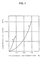
- Fig. 7 is a graph showing pressure-resistant characteristics of the composite material of the present invention and a conventional composite material.
- the composite material comprises a rubber material such as nitrile rubber and chloroprene rubber, a filler such as graphite and mica, an inorganic fiber such as glass fiber and an organic fiber such as aromatic polyamide fiber and aromatic polyimide fiber.
- the total height of the cylinder head gasket, a cylinder head and a cylinder block can be regulated; a member for heightening sealing property can be provided extremely easily; when contact pressure with a high load is applied to, the laminated thin plates can be conformed to deformation of a cylinder head or a cylinder block because of the coating layers and also flow breaking or peeling of the coating layers does not occur; and a creep phenomenon is not caused by thermal influence.
- both of the outermost thick coating layers are contacted with the processed surfaces of a cylinder head and a cylinder block which are counterpart members to absorb roughness of the processed surfaces, and the coating layer(s) is/are prevented from being formed to have an unnecessary thickness by making the thin plates adjacent with the coating layer(s) which is/are thin but have a thickness enough to retain airtightness between the plates, sandwiched therebetween, whereby the total height of the gasket itself can be suppressed, and even when a high load is applied to, a mechanical creep phenomenon is not caused.
- a cylinder head gasket 1 (hereinafter abbreviated to as “gasket 1") according to the first embodiment of the present invention is to be interposed between a cylinder head 2 (hereinafter abbreviated to as “head 2”) and a cylinder block 3 (hereinafter abbreviated to as “block 3").
- Fig. 1 is a cross-sectional view thereof.
- Fig. 2 is a plan view of the gasket 1;
- Fig. 3a is an enlarged sectional view of an A-A section of the gasket 1 of Fig. 2;
- Fig. 3b and Fig. 3c are each an enlarged sectional view of a B-B section of the gasket 1 of Fig 2 showing different embodiments.
- the gasket 1 is constituted by laminating three surface-treated thin steel plates 4 to 6.
- coating layers 8 On the back surfaces of the thin plates 4 and 6, i.e., at the sides of the surfaces adjacent to the thin plate 5, coating layers 8 having a desired thickness of 60 to 100 ⁇ m of the same kind of the above composite material are provided, respectively.
- the above coating layers 7 are formed so as to have the same thickness as that of the coating layers 8.
- the thicknesses of the coating layers 7 and 8 should be selected variously in consideration of not only precisions of surface roughness of the thin plates 4 to 6 themselves constituting the gasket 1 and surface roughness of the head 2 and the block 3 but also use conditions of the gasket 1.
- the thickness of the coating layers 7 is preferably 100 ⁇ m or more, and that of the coating layers 8 is preferably 100 ⁇ m or less.
- Fig. 1 the case where the coating layers 7 having the same thickness are formed on the outer surfaces of the thin plate 4 and the thin plate 6 is illustrated, but the present invention is not limited thereby.
- the coating layers 7 may be formed so that they are different in thickness depending on surface roughness or the like of the head 2 and the block 3.
- the coating layers 8 are formed on the back surfaces of the thin plates 4 and 6 is illustrated, but the present invention is not limited thereby.
- the coating layers 8 may be formed on both surfaces of the thin plate 5 in place of the back surfaces of the thin plates 4 and 6, or the coating layers 8 may be formed on the back surfaces of the thin plates 4 and 6 and both surfaces of the thin place 5, respectively, so that the coating layers 8 has a total thickness of 60 ⁇ m or less.
- the composite material of the present invention could stand a compressive load exceeding 150 Mega pascal (MPa) and allow thickness deformation exceeding 30 %.
- the conventional composite material was crushed when applying a compressive load of 75 MPa which was a half of the above compressive load. This crush point was thickness deformation of less than 10 %. The crush point is marked with "X" in Fig. 7.
- the gasket 1 as described above is constituted by the laminated thin plates 4 to 6, whereby the total height of the gasket 1, the head 2 and the block 3 can be regulated. Additionally, even when a high load is applied to and the gasket 1 is interposed between the head 2 and the block 3, the coating layers 8 are provided on the contacting surface of the laminated thin plates 4 and 5 and that of the laminated thin plates 5 and 6 so that the gasket 1 can be conformed to deformation of the head 2 or the block 3. Moreover, the composite material is used for the coating layers 7 and 8 so that flow breaking or peeling of the coating layers 7 and 8 does not occur and a creep phenomenon is not caused by thermal influence from the block 3 or the like.
- the coating layers 7 and the coating layers 8 are prevented from being formed to have an unnecessary thickness by absorbing surface roughness of the surfaces contacting with counterpart members between which the gasket 1 is interposed, i.e., the head 2 and the block 3 by the coating layers 7 and retaining airtightness between the than plates 4 to 6 by the coating layers 8 which are thinner than the coating layers 7, whereby the total height of the gasket 1 itself can be suppressed; even when a high load is applied to, a mechanical creep phenomenon is not caused; and durability is obtained.
- a member for heightening sealing property e.g., an O-ring and a mandrel
- the above member can be provided extremely easily as compared with a gasket constituted by a single thin plate described above.
- a concave portion 5a is formed at the thin plate 5 which is an intermediate layer, whereby a member 9 (composed of 9a and 9b) for heightening sealing property can be engaged with the concave portion 5a.
- the member 9 comprises an O-ring 9a made of rubber and a mandrel 9b for reinforcing the ring 9a which are molded integrally, and the mandrel 9b is engaged with the concave portion 5a.
- the gasket 1 having mechanical strength and durability against flow breaking, peeling or creep, in which the member 9 for heightening sealing property of the combustion room bores 1a or the fluid-passing bores 1b can be provided extremely easily.
- a cylinder head gasket 31 according to the second embodiment of the present invention is also to be interposed between the cylinder head 2 and the cylinder block 3, and a plan shape thereof is the same as shown in Fig. 2.
- Fig. 3b and Fig. 3c are each an enlarged sectional view of a B-B section of Fig. 2.
- the gasket 31 having a sectional constitution shown in Fig. 3b or Fig. 3c is the same as the gasket of Fig. 3a in that the gasket 31 is constituted by laminating three surface-treated steel thin plates 4, 35a and 6.
- the gasket 31 shown in Fig. 3b or Fig. 3c is different from the gasket of Fig. 3a in the following points. That is, the gasket 1 of Fig. 3a showing the first embodiment of the present invention has a constitution that in order to prevent leakage of a combustion gas, cooling water and the like, the member 9 for heightening sealing property, for example, the O-ring 9a and the mandrel 9b are provided externally at the circumferential edges of the plural combustion room bores 1a or the plural fluid-passing bores 1b.
- the member 9 for heightening sealing property requires additional processing step(s) for such provision.
- a surface-coating layer having a sufficient thickness cannot be provided, as a method in which an externally provided sealing member is not used, there may be mentioned a conventional technique that a bead-processed portion 25 is provided in order to form local sealing stress at a portion contacting with a counterpart flange surface, as shown in Fig. 4 and 5. In that case, there is a problem that peeling or abrasion of a coating layer at the bead-processed portion 25 occurs.
- bead processing is applied based on an inventive finding that by a coating layer of a surface contacting with a counterpart flange having a sufficient thickness and also making thinner a coating layer of an intermediate contacting surface to which bead processing is to be applied, necessary sealing stress can be formed at the surface contacting with the counterpart flange by subjecting only the intermediate layer to bead processing.
- Fig. 3b shows an embodiment that a bead-processed portion 35b is provided only at an intermediate layer 35a, and the coating layers 7 and 8 are provided on both surfaces of the outer thin plates 4 and 6.
- FIG. 3c shows an embodiment that a bead-processed portion 35b is provided only at an intermediate layer 35a, and the coating layers 8c are provided on both surfaces of the intermediate layer 35a.
- the embodiment that coating layers 8c are coated on both surfaces of the intermediate layer 35a illustrated in Fig. 3c is not limited to such constitution, and the coating layer 8c may be provided only on either surface of the intermediate layer 35a, and coating may be applied to a side facing to a thin plate adjacent to a surface which is not coated.
- the gasket 1 constituted by laminating the three thin steel plates 4 to 6, which is considered to be used most frequently from the standpoints of productivity and cost is explained.
- four or more thin plates may be laminated depending on conditions under which a gasket is used.
- a composite material (trade name: 4840AH-2, available from Asktechnika Corporation, Japan) with a dried thickness of 120 ⁇ m.
- the composite material comprises 60 % by weight of a filler composed of a mixture of silica, kaolin and mica; 20 % by weight of a binder (butadiene-acrylonitrile rubber: acrylonitrile content in the binder of 35 % by weight) and 20 % by weight of a fiber composed of a mixture of an aromatic polyamide fiber and rock wool with a weight ratio of 1 : 1.
- a composite material (trade name: 4840AH-2, available from Asktechnika Corporation, Japan) with a dried thickness of 120 ⁇ m.
- the composite material comprises 60 % by weight of a filler composed of a mixture of silica, kaolin and mica; 20 % by weight of a binder (butadiene-acrylonitrile rubber: acrylonitrile content in the binder of 35 % by weight) and 20 % by weight of a fiber
- This both-surface coated steel plate is subjected to blanking with a blanking press with a predetermined shape to have cylinder bores and fluid-passing bores.
- a stainless plate to which the same blanking treatment as mentioned above is subjected and a part of blanking bores is subjected to beading treatment is prepared.
- This beading-treated steel plate is sandwiched between two sheets of the above both-surface coated steel plates so that the thicker coating layers of the respective both-surface coated steel plates are positioned at the outermost surface of the laminated plates to prepare a cylinder head gasket of the present invention.
- To a part of the blanking bores is attached an O-ring to obtain a final product.
- the gasket when contact pressure with a high load is applied to, the gasket can be conformed to deformation of a cylinder head or a cylinder block due to the coating layers, flow breaking or peeling of the coating layers does not occur, and a creep phenomenon is not caused by thermal influence.
- the cylinder head gasket of the present invention roughness of the processed surfaces of counterpart members can be absorbed, and the coating layers are formed so that airtightness between the thin plates can be retained, whereby the total height of the gasket itself can be suppressed, and even when a high load is applied to, a mechanical creep phenomenon of the coating layers does not occur, and durability is improved.
Abstract
Description
- Filler:
- preferably 40 to 85 % by weight, more preferably about 60 % by weight based on the total weight of the composite material kaolin, silica, mica or antigorite average particle size; preferably 1 to 50 µm, more preferably about 10 µm
- Binder:
- preferably 5 to 30 % by weight, more preferably about 20 % by weight based on the same nitrile rubber, butadiene-acrylonitrile rubber (NBR) or chloroprene rubber content of acrylonitrile in the binder; preferably 20 to 50 % by weight, more preferably about 33 to 35 % by weight
- Fiber:
- preferably 10 to 40 % by weight, more preferably about 20 % by weight based on the same aromatic polyamide fiber, asbestos or rock wool
- Size of test strips:
- 5 x 15 mm
- Pre-treatment conditions of test strips:
- Test strips were dipped in a long life coolant diluted with 50 % tap water heated at 100 °C, for 1 hour.
- Test method:
- The test strips were placed on a platen of a material compression tester Autograph DSS-25T (trade name) produced by Shimadzu Seisakusho and compressed by a compression jig having a size of about 30 mm in diameter. The compression rate was 0.5 mm/min.
Claims (6)
- A cylinder head gasket which comprises:plural thin metal plates each having at least cylinder bores and fluid-passing bores being laminated to constitute laminated thin plates;the surfaces of the outermost thin plates of the laminated thin plates being coated with a composite material, respectively; andthe surface of at least one of the thin plates adjacent to each other of the laminated thin plates being coated with the composite material to form a coating layer, whereby the adjacent thin plates are laminated with the coating layer sandwiched therebetween.
- The gasket according to Claim 1, wherein beads surrounding the fluid-passing bores are formed only on the intermediate thin plates except for the outermost thin plates among the thin plates constituting the laminated thin plates.
- A cylinder head gasket which comprises:plural thin metal plates each having at least cylinder bores and fluid-passing bores being laminated to constitute laminated thin plates;the surfaces of the outermost thin plates of the laminated thin plates being coated with a composite material, respectively; andthe surface of at least one of the thin plates adjacent to each other of the laminated thin plates being coated with the composite material to form a coating layer, whereby the adjacent thin plates are laminated with the coating layer sandwiched therebetween,
wherein each of the coating layers on the surfaces of the outermost thin plates is formed so as to be thicker than the coating layer formed between the adjacent thin plates. - The gasket according to Claim 3, wherein beads surrounding the fluid-passing bores are formed only on the intermediate thin plates except for the outermost thin plates among the thin plates constituting the laminated thin plates.
- A cylinder head gasket which comprises:plural thin metal plates each having at least cylinder bores and fluid-passing bores being laminated to constitute laminated thin plates;the surfaces of the outermost thin plates of the laminated thin plates being coated with a composite material containing a fiber in addition to a binder and a filler, respectively; andthe surface of at least one of the thin plates adjacent to each other of the laminated thin plates being coated with the composite material to form a coating layer, whereby the adjacent thin plates are laminated with the coating layer sandwiched therebetween,
wherein each of the coating layers on the surfaces of the outermost thin plates is formed so as to be thicker than the coating layer formed between the adjacent thin plates. - The gasket according to Claim 5, wherein beads surrounding the fluid-passing bores are formed only on the intermediate thin plates except for the outermost thin plates among the thin plates constituting the laminated thin plates.
Priority Applications (5)
| Application Number | Priority Date | Filing Date | Title |
|---|---|---|---|
| JP7203652A JPH0953726A (en) | 1995-08-09 | 1995-08-09 | Gasket for cylinder head |
| EP96120820A EP0851155B1 (en) | 1995-08-09 | 1996-12-23 | Cylinder head gasket |
| ES96120820T ES2216033T3 (en) | 1995-08-09 | 1996-12-23 | HEAD GASKET. |
| DE69631832T DE69631832T2 (en) | 1995-08-09 | 1996-12-23 | Cylinder head gasket |
| US08/774,187 US6139024A (en) | 1995-08-09 | 1996-12-26 | Cylinder head gasket |
Applications Claiming Priority (3)
| Application Number | Priority Date | Filing Date | Title |
|---|---|---|---|
| JP7203652A JPH0953726A (en) | 1995-08-09 | 1995-08-09 | Gasket for cylinder head |
| EP96120820A EP0851155B1 (en) | 1995-08-09 | 1996-12-23 | Cylinder head gasket |
| US08/774,187 US6139024A (en) | 1995-08-09 | 1996-12-26 | Cylinder head gasket |
Publications (2)
| Publication Number | Publication Date |
|---|---|
| EP0851155A1 true EP0851155A1 (en) | 1998-07-01 |
| EP0851155B1 EP0851155B1 (en) | 2004-03-10 |
Family
ID=27237497
Family Applications (1)
| Application Number | Title | Priority Date | Filing Date |
|---|---|---|---|
| EP96120820A Expired - Lifetime EP0851155B1 (en) | 1995-08-09 | 1996-12-23 | Cylinder head gasket |
Country Status (5)
| Country | Link |
|---|---|
| US (1) | US6139024A (en) |
| EP (1) | EP0851155B1 (en) |
| JP (1) | JPH0953726A (en) |
| DE (1) | DE69631832T2 (en) |
| ES (1) | ES2216033T3 (en) |
Cited By (3)
| Publication number | Priority date | Publication date | Assignee | Title |
|---|---|---|---|---|
| DE10244853A1 (en) * | 2002-09-26 | 2004-04-15 | Federal-Mogul Sealing Systems Gmbh | Multi-layer cylinder head gasket |
| EP1522770A1 (en) * | 2003-10-07 | 2005-04-13 | Bayerische Motoren Werke Aktiengesellschaft | Gasket |
| DE102007022423B4 (en) | 2006-05-12 | 2018-12-27 | Ishikawa Gasket Co., Ltd. | Multilayer cylinder head gasket with rubber ring |
Families Citing this family (13)
| Publication number | Priority date | Publication date | Assignee | Title |
|---|---|---|---|---|
| DE19735390A1 (en) * | 1997-08-14 | 1999-02-25 | Reinz Dichtungs Gmbh | Sealant coating useful in ventilation joints, oil tanks, gear flanges, compressors and axles |
| JP2002013640A (en) * | 2000-06-29 | 2002-01-18 | Uchiyama Mfg Corp | Cylinder head gasket |
| US7200932B2 (en) * | 2004-01-13 | 2007-04-10 | Federal-Mogul Worldwide, Inc. | Laser welded multi-layered steel gasket assembly |
| US20070029738A1 (en) * | 2005-08-05 | 2007-02-08 | Person Dennis F | MLS gasket sealability with bronze addition |
| JP2008202625A (en) * | 2007-02-16 | 2008-09-04 | Ishikawa Gasket Co Ltd | Laminated gasket |
| US20080260455A1 (en) * | 2007-04-17 | 2008-10-23 | Air Products And Chemicals, Inc. | Composite Seal |
| CN102483161B (en) * | 2009-08-19 | 2014-11-05 | 费德罗-莫格尔公司 | Cylinder head gasket assembly |
| KR101527569B1 (en) * | 2014-01-06 | 2015-06-09 | 제일 이엔에스 주식회사 | Manufacturing method of rubber o-ring type gasket having kammprofile |
| KR101960335B1 (en) * | 2015-03-13 | 2019-03-21 | 이종철 | Gasket and the manufacturing method thereof |
| US10927790B2 (en) * | 2015-11-20 | 2021-02-23 | Nok Corporation | Cylinder head gasket |
| JP6905052B2 (en) * | 2016-09-09 | 2021-07-21 | リー、ジョンチョルLEE, Jong Chul | gasket |
| US11268616B2 (en) * | 2017-10-06 | 2022-03-08 | Virginia Sealing Products, Inc. | Envelope gasket |
| US11703013B1 (en) * | 2022-03-03 | 2023-07-18 | Caterpillar Inc. | Engine head gasket having anti-preignition wrap and method of making same |
Citations (3)
| Publication number | Priority date | Publication date | Assignee | Title |
|---|---|---|---|---|
| EP0431227A1 (en) * | 1989-11-20 | 1991-06-12 | Ishikawa Gasket Co. Ltd. | A steel laminate gasket |
| WO1993008420A1 (en) * | 1991-10-21 | 1993-04-29 | Mccord Payen Incorporated | Embossed composite gasket |
| US5490681A (en) * | 1994-09-22 | 1996-02-13 | Dana Corporation | Three layer metal gasket with dual coating |
Family Cites Families (14)
| Publication number | Priority date | Publication date | Assignee | Title |
|---|---|---|---|---|
| US2074388A (en) * | 1934-06-28 | 1937-03-23 | Gen Motors Corp | Gasket |
| US2116000A (en) * | 1935-03-08 | 1938-05-03 | Victor Mfg & Gasket Co | Coating for gaskets and the like |
| US2070918A (en) * | 1935-03-11 | 1937-02-16 | Victor Mfg & Gasket Co | Coated gasket |
| US2753199A (en) * | 1952-05-21 | 1956-07-03 | Victor Mfg & Gasket Co | Gasket |
| US3784212A (en) * | 1972-05-22 | 1974-01-08 | Detroit Gasket Mfg Co | Composite gasket |
| US4325559A (en) * | 1980-05-12 | 1982-04-20 | Felt Products Mfg. Co. | Erosion resistant gasket |
| JPS57188056A (en) * | 1981-05-15 | 1982-11-18 | Fuji Xerox Co Ltd | Paper transport method of copying machine |
| JPS6040165A (en) * | 1983-08-12 | 1985-03-02 | Sumitomo Chem Co Ltd | Production of fluoran compound |
| US4834279A (en) * | 1987-08-03 | 1989-05-30 | Fel-Pro Incorporated | Gasketing material and method of making same by densifying adhesive bonded facing layers to a metallic core |
| US4826708A (en) * | 1987-08-03 | 1989-05-02 | Ishikawa Gasket Co., Ltd. | Method of manufacturing a steel plate with a seal coating for a steel laminate gasket |
| US5122214A (en) * | 1988-07-18 | 1992-06-16 | Fel-Pro Incorporated | Method of making a rubber laminated gasket |
| US4898396A (en) * | 1988-08-11 | 1990-02-06 | Ishikawa Gasket Co., Ltd. | Steel laminate gasket |
| EP0468526B1 (en) * | 1990-07-26 | 1995-04-05 | Taiho Kogyo Co., Ltd. | Metal gasket |
| US5582415A (en) * | 1993-08-31 | 1996-12-10 | Kokusan Parts Industry Co., Ltd. | Metal gasket |
-
1995
- 1995-08-09 JP JP7203652A patent/JPH0953726A/en active Pending
-
1996
- 1996-12-23 EP EP96120820A patent/EP0851155B1/en not_active Expired - Lifetime
- 1996-12-23 DE DE69631832T patent/DE69631832T2/en not_active Expired - Lifetime
- 1996-12-23 ES ES96120820T patent/ES2216033T3/en not_active Expired - Lifetime
- 1996-12-26 US US08/774,187 patent/US6139024A/en not_active Expired - Lifetime
Patent Citations (3)
| Publication number | Priority date | Publication date | Assignee | Title |
|---|---|---|---|---|
| EP0431227A1 (en) * | 1989-11-20 | 1991-06-12 | Ishikawa Gasket Co. Ltd. | A steel laminate gasket |
| WO1993008420A1 (en) * | 1991-10-21 | 1993-04-29 | Mccord Payen Incorporated | Embossed composite gasket |
| US5490681A (en) * | 1994-09-22 | 1996-02-13 | Dana Corporation | Three layer metal gasket with dual coating |
Cited By (4)
| Publication number | Priority date | Publication date | Assignee | Title |
|---|---|---|---|---|
| DE10244853A1 (en) * | 2002-09-26 | 2004-04-15 | Federal-Mogul Sealing Systems Gmbh | Multi-layer cylinder head gasket |
| DE10244853B4 (en) * | 2002-09-26 | 2005-06-23 | Federal-Mogul Sealing Systems Gmbh | Multi-layered cylinder head gasket |
| EP1522770A1 (en) * | 2003-10-07 | 2005-04-13 | Bayerische Motoren Werke Aktiengesellschaft | Gasket |
| DE102007022423B4 (en) | 2006-05-12 | 2018-12-27 | Ishikawa Gasket Co., Ltd. | Multilayer cylinder head gasket with rubber ring |
Also Published As
| Publication number | Publication date |
|---|---|
| US6139024A (en) | 2000-10-31 |
| ES2216033T3 (en) | 2004-10-16 |
| JPH0953726A (en) | 1997-02-25 |
| EP0851155B1 (en) | 2004-03-10 |
| DE69631832T2 (en) | 2005-02-10 |
| DE69631832D1 (en) | 2004-04-15 |
Similar Documents
| Publication | Publication Date | Title |
|---|---|---|
| US6139024A (en) | Cylinder head gasket | |
| EP0721077B1 (en) | Metal gasket | |
| KR930001357Y1 (en) | Steel laminate gasket for an internal combustion epublishing system of brand tag and label using converter ngine | |
| US5277434A (en) | Multiple layer cylinder head gasket | |
| US7726662B2 (en) | Stopped-active type cylinder head gasket | |
| EP1180619B2 (en) | Cylinder head gasket with different seal coatings | |
| US7669859B2 (en) | Cylinder head gasket | |
| US5588657A (en) | Laminated metal gasket with diverse bead height | |
| KR20020012487A (en) | Head gasket | |
| JP3753413B2 (en) | Multi-cylinder head gasket | |
| US5634645A (en) | Sheet-like gasket with overlapped peripheral portions | |
| EP1564453A1 (en) | Cylinder head gasket | |
| EP0725241B1 (en) | Metal gasket | |
| CA2276072A1 (en) | Gasket with dynamic embossment | |
| US6135459A (en) | Metal gasket | |
| US20050200083A1 (en) | Cylinder head gasket | |
| KR100411148B1 (en) | Head gasket | |
| US7401790B2 (en) | Metal gasket with rigid seal | |
| US4852893A (en) | Elastomeric coated perforated metal core composite gasket and method of making same | |
| US20050093248A1 (en) | Cylinder head gasket | |
| WO1993008420A1 (en) | Embossed composite gasket | |
| EP0592142B1 (en) | Head gasket | |
| EP0845621A1 (en) | Metal gasket | |
| US5482014A (en) | High output automotive engine gasket assembly and method of making same | |
| JPH06100285B2 (en) | Cylinder / Head / Gasket |
Legal Events
| Date | Code | Title | Description |
|---|---|---|---|
| PUAI | Public reference made under article 153(3) epc to a published international application that has entered the european phase |
Free format text: ORIGINAL CODE: 0009012 |
|
| AK | Designated contracting states |
Kind code of ref document: A1 Designated state(s): DE ES FR GB IT NL SE |
|
| AX | Request for extension of the european patent |
Free format text: AL;LT;LV;RO;SI |
|
| 17P | Request for examination filed |
Effective date: 19980908 |
|
| AKX | Designation fees paid |
Free format text: DE ES FR GB IT NL SE |
|
| RBV | Designated contracting states (corrected) |
Designated state(s): DE ES FR GB IT NL SE |
|
| 17Q | First examination report despatched |
Effective date: 20010531 |
|
| REG | Reference to a national code |
Ref country code: GB Ref legal event code: FG4D |
|
| GRAH | Despatch of communication of intention to grant a patent |
Free format text: ORIGINAL CODE: EPIDOS IGRA |
|
| GRAS | Grant fee paid |
Free format text: ORIGINAL CODE: EPIDOSNIGR3 |
|
| GRAA | (expected) grant |
Free format text: ORIGINAL CODE: 0009210 |
|
| AK | Designated contracting states |
Kind code of ref document: B1 Designated state(s): DE ES FR GB IT NL SE |
|
| REG | Reference to a national code |
Ref country code: SE Ref legal event code: TRGR |
|
| REF | Corresponds to: |
Ref document number: 69631832 Country of ref document: DE Date of ref document: 20040415 Kind code of ref document: P |
|
| REG | Reference to a national code |
Ref country code: ES Ref legal event code: FG2A Ref document number: 2216033 Country of ref document: ES Kind code of ref document: T3 |
|
| ET | Fr: translation filed | ||
| PLBE | No opposition filed within time limit |
Free format text: ORIGINAL CODE: 0009261 |
|
| STAA | Information on the status of an ep patent application or granted ep patent |
Free format text: STATUS: NO OPPOSITION FILED WITHIN TIME LIMIT |
|
| 26N | No opposition filed |
Effective date: 20041213 |
|
| REG | Reference to a national code |
Ref country code: FR Ref legal event code: PLFP Year of fee payment: 20 |
|
| PGFP | Annual fee paid to national office [announced via postgrant information from national office to epo] |
Ref country code: GB Payment date: 20151221 Year of fee payment: 20 |
|
| PGFP | Annual fee paid to national office [announced via postgrant information from national office to epo] |
Ref country code: FR Payment date: 20151218 Year of fee payment: 20 Ref country code: SE Payment date: 20151222 Year of fee payment: 20 Ref country code: ES Payment date: 20151218 Year of fee payment: 20 Ref country code: NL Payment date: 20151221 Year of fee payment: 20 |
|
| PGFP | Annual fee paid to national office [announced via postgrant information from national office to epo] |
Ref country code: DE Payment date: 20151230 Year of fee payment: 20 |
|
| PGFP | Annual fee paid to national office [announced via postgrant information from national office to epo] |
Ref country code: IT Payment date: 20151222 Year of fee payment: 20 |
|
| REG | Reference to a national code |
Ref country code: DE Ref legal event code: R071 Ref document number: 69631832 Country of ref document: DE |
|
| REG | Reference to a national code |
Ref country code: NL Ref legal event code: MK Effective date: 20161222 |
|
| REG | Reference to a national code |
Ref country code: GB Ref legal event code: PE20 Expiry date: 20161222 |
|
| PG25 | Lapsed in a contracting state [announced via postgrant information from national office to epo] |
Ref country code: GB Free format text: LAPSE BECAUSE OF EXPIRATION OF PROTECTION Effective date: 20161222 |
|
| REG | Reference to a national code |
Ref country code: SE Ref legal event code: EUG |
|
| PG25 | Lapsed in a contracting state [announced via postgrant information from national office to epo] |
Ref country code: ES Free format text: LAPSE BECAUSE OF EXPIRATION OF PROTECTION Effective date: 20161224 |