EP0851138A2 - Flüssigkeitskupplung - Google Patents
Flüssigkeitskupplung Download PDFInfo
- Publication number
- EP0851138A2 EP0851138A2 EP97122917A EP97122917A EP0851138A2 EP 0851138 A2 EP0851138 A2 EP 0851138A2 EP 97122917 A EP97122917 A EP 97122917A EP 97122917 A EP97122917 A EP 97122917A EP 0851138 A2 EP0851138 A2 EP 0851138A2
- Authority
- EP
- European Patent Office
- Prior art keywords
- impeller
- runner
- speed
- fluid coupling
- casing
- Prior art date
- Legal status (The legal status is an assumption and is not a legal conclusion. Google has not performed a legal analysis and makes no representation as to the accuracy of the status listed.)
- Granted
Links
- 230000008878 coupling Effects 0.000 title claims abstract description 34
- 238000010168 coupling process Methods 0.000 title claims abstract description 34
- 238000005859 coupling reaction Methods 0.000 title claims abstract description 34
- 239000012530 fluid Substances 0.000 title claims abstract description 32
- 239000000463 material Substances 0.000 claims abstract description 15
- 229910001069 Ti alloy Inorganic materials 0.000 claims abstract description 13
- 230000005484 gravity Effects 0.000 claims abstract description 12
- 229910000838 Al alloy Inorganic materials 0.000 claims abstract description 7
- 230000035882 stress Effects 0.000 description 19
- 239000003921 oil Substances 0.000 description 7
- 230000002093 peripheral effect Effects 0.000 description 7
- 229910000851 Alloy steel Inorganic materials 0.000 description 6
- 239000010936 titanium Substances 0.000 description 6
- XEEYBQQBJWHFJM-UHFFFAOYSA-N Iron Chemical compound [Fe] XEEYBQQBJWHFJM-UHFFFAOYSA-N 0.000 description 4
- RTAQQCXQSZGOHL-UHFFFAOYSA-N Titanium Chemical compound [Ti] RTAQQCXQSZGOHL-UHFFFAOYSA-N 0.000 description 3
- 229910052719 titanium Inorganic materials 0.000 description 3
- XAGFODPZIPBFFR-UHFFFAOYSA-N aluminium Chemical compound [Al] XAGFODPZIPBFFR-UHFFFAOYSA-N 0.000 description 2
- 229910052782 aluminium Inorganic materials 0.000 description 2
- 239000010949 copper Substances 0.000 description 2
- 238000009434 installation Methods 0.000 description 2
- 239000011777 magnesium Substances 0.000 description 2
- 239000011572 manganese Substances 0.000 description 2
- 238000004519 manufacturing process Methods 0.000 description 2
- 230000008646 thermal stress Effects 0.000 description 2
- OKTJSMMVPCPJKN-UHFFFAOYSA-N Carbon Chemical compound [C] OKTJSMMVPCPJKN-UHFFFAOYSA-N 0.000 description 1
- RYGMFSIKBFXOCR-UHFFFAOYSA-N Copper Chemical compound [Cu] RYGMFSIKBFXOCR-UHFFFAOYSA-N 0.000 description 1
- FYYHWMGAXLPEAU-UHFFFAOYSA-N Magnesium Chemical compound [Mg] FYYHWMGAXLPEAU-UHFFFAOYSA-N 0.000 description 1
- PWHULOQIROXLJO-UHFFFAOYSA-N Manganese Chemical compound [Mn] PWHULOQIROXLJO-UHFFFAOYSA-N 0.000 description 1
- XUIMIQQOPSSXEZ-UHFFFAOYSA-N Silicon Chemical compound [Si] XUIMIQQOPSSXEZ-UHFFFAOYSA-N 0.000 description 1
- 229910000831 Steel Inorganic materials 0.000 description 1
- 229910000883 Ti6Al4V Inorganic materials 0.000 description 1
- QVGXLLKOCUKJST-UHFFFAOYSA-N atomic oxygen Chemical compound [O] QVGXLLKOCUKJST-UHFFFAOYSA-N 0.000 description 1
- 229910052799 carbon Inorganic materials 0.000 description 1
- VNTLIPZTSJSULJ-UHFFFAOYSA-N chromium molybdenum Chemical compound [Cr].[Mo] VNTLIPZTSJSULJ-UHFFFAOYSA-N 0.000 description 1
- 229910052802 copper Inorganic materials 0.000 description 1
- -1 e.g. Inorganic materials 0.000 description 1
- 229910052742 iron Inorganic materials 0.000 description 1
- 229910052749 magnesium Inorganic materials 0.000 description 1
- 229910052748 manganese Inorganic materials 0.000 description 1
- 239000000203 mixture Substances 0.000 description 1
- 230000004048 modification Effects 0.000 description 1
- 238000012986 modification Methods 0.000 description 1
- 229910052760 oxygen Inorganic materials 0.000 description 1
- 239000001301 oxygen Substances 0.000 description 1
- VSZWPYCFIRKVQL-UHFFFAOYSA-N selanylidenegallium;selenium Chemical compound [Se].[Se]=[Ga].[Se]=[Ga] VSZWPYCFIRKVQL-UHFFFAOYSA-N 0.000 description 1
- 229910052710 silicon Inorganic materials 0.000 description 1
- 239000010703 silicon Substances 0.000 description 1
- 230000003068 static effect Effects 0.000 description 1
- 239000010959 steel Substances 0.000 description 1
- JBQYATWDVHIOAR-UHFFFAOYSA-N tellanylidenegermanium Chemical compound [Te]=[Ge] JBQYATWDVHIOAR-UHFFFAOYSA-N 0.000 description 1
- LEONUFNNVUYDNQ-UHFFFAOYSA-N vanadium atom Chemical compound [V] LEONUFNNVUYDNQ-UHFFFAOYSA-N 0.000 description 1
Images

Classifications
-
- F—MECHANICAL ENGINEERING; LIGHTING; HEATING; WEAPONS; BLASTING
- F16—ENGINEERING ELEMENTS AND UNITS; GENERAL MEASURES FOR PRODUCING AND MAINTAINING EFFECTIVE FUNCTIONING OF MACHINES OR INSTALLATIONS; THERMAL INSULATION IN GENERAL
- F16H—GEARING
- F16H41/00—Rotary fluid gearing of the hydrokinetic type
- F16H41/24—Details
-
- F—MECHANICAL ENGINEERING; LIGHTING; HEATING; WEAPONS; BLASTING
- F16—ENGINEERING ELEMENTS AND UNITS; GENERAL MEASURES FOR PRODUCING AND MAINTAINING EFFECTIVE FUNCTIONING OF MACHINES OR INSTALLATIONS; THERMAL INSULATION IN GENERAL
- F16D—COUPLINGS FOR TRANSMITTING ROTATION; CLUTCHES; BRAKES
- F16D33/00—Rotary fluid couplings or clutches of the hydrokinetic type
- F16D33/18—Details
Definitions
- the present invention relates to a fluid coupling, and more particularly to a fluid coupling which is used for controlling rotational speeds of a boiler feed pump, a descaling pump or the like in a thermal power plant, an iron production plant or the like, and is operable at high speeds.
- variable speed regulators for operating high-speed, large-capacity pumps and blowers with high efficiency as energy saving apparatus for use with rotary machinery.
- a fluid coupling assembly which comprises speed-increasing gear trains and a variable-speed fluid coupling which are integrally housed in a casing, the variable-speed fluid coupling having an impeller runner assembly mounted on a high-speed shaft of the speed-increasing gear train.
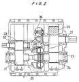
- FIG. 2 of the accompanying drawings shows a conventional fluid coupling.
- the conventional fluid coupling has an input shaft 21 with a large gear 22 mounted thereon, and a drive shaft 23 disposed parallel to the input shaft 21 and supporting a small gear 24 held in mesh with the large gear 22.
- the large gear 22 and the small gear 24 which are held in mesh with each other jointly serve as a speed-increasing gear train for increasing the rotational speed of the drive shaft 23 as compared with the rotational speed of the input shaft 21.
- the conventional fluid coupling also has a driven shaft 25 disposed adjacent to and coaxially with the drive shaft 23.
- An impeller 26 is coupled to an inner end of the drive shaft 23, and a runner 27 is coupled to an inner end of the driven shaft 25.
- the impeller 26 is fixed to an impeller casing 28 which houses the runner 27 therein.
- the impeller 26, the runner 27 and the impeller casing 28 jointly define a working fluid chamber with a scoop tube 30 disposed therein for continuously varying the rotational speed of a load such as a pump coupled to the fluid coupling from a minimum speed level to a maximum speed level.
- a large gear 31 is mounted on the driven shaft 25 and held in mesh with a small gear 33 mounted on an output shaft 32 which extends parallel to the driven shaft 25.
- the large gear 31 and the small gear 33 also jointly serve as a speed-increasing gear train for increasing the rotational speed of the output shaft 32 as compared with the rotational speed of the driven shaft 25.
- Auxiliary machines such as a main oil pump 36 and an auxiliary oil pump (not shown) are connected to the input shaft 21 through gears 35.
- the main oil pump 36 axially extends in a direction normal to the sheet of FIG. 1.
- the conventional fluid coupling meets such a high speed requirement by increasing the rotational speed with the two speed-increasing gear trains, positioned respectively on input and output sides of the impeller 26 and the runner 27, such that the peripheral speeds of effective-diameter portions of the impeller 26 and the runner 27 will not exceed a certain reference value which normally ranges from about 150 m/s to 165 m/s.
- the impeller 26, the runner 27 and the impeller casing 28 are protected from fracture or fatigue-induced fracture due to various stresses including centrifugal stresses developed in the impeller 26, the runner 27 and the impeller casing 28 when power is transmitted thereto, stresses and thermal stresses developed by a centrifugal hydraulic pressure in the working fluid chamber, and stresses caused when torque is transmitted.
- outer circumferential open ends of the impeller 26 and the impeller casing 28 are of an overhanging and cantilevered structure, the peripheral speeds of the impeller 26 and the impeller casing 28 are suppressed because their outer circumferential open ends are most subject to fatigue-induced fracture.
- the two speed-increasing gear trains are disposed respectively on the input and output sides of the impeller 26 and the runner 27 to meet rotational speed requirements of the load such as a pump.
- the two speed-increasing gear trains have suffered various disadvantages in that the fluid coupling is large in overall size and weight, takes up a large installation space, and is highly costly to manufacture.
- a fluid coupling comprising: an input shaft having a speed-increasing gear train; a working fluid chamber defined by an impeller, a runner and an impeller casing; an output shaft having the runner operatively combined with the impeller; the impeller casing being made of a material having a small specific gravity and a high allowable stress range for reducing centrifugal stresses developed therein when the impeller casing rotates at high speeds.
- the speed-increasing gear train is provided only on the input shaft, i.e., an input side of the impeller and the runner.
- the speed-increasing gear train is not provided on an output side of the impeller and the runner.
- the peripheral speeds of the impeller and the runner are high, and hence they are subject to centrifugal stresses that increase in proportion to the square of the peripheral speeds. If the peripheral speeds of the impeller and the runner exceed a certain limit, the impeller and the runner would be subjected to fracture or fatigue-induced fracture.
- peripheral speeds of the impeller and the runner measured at their effective-diameter portions thereof should not exceed a value ranging from about 150 m/s to 165 m/s if the impeller and the runner were made of an alloy steel for use in machine structures.
- the impeller casing which is connected to the impeller in an overhanging and cantilevered fashion, or the impeller casing and the impeller are made of a material having a small specific gravity and a high allowable stress range such as a titanium alloy rather than an alloy steel for use in machine structures. Since the specific gravity of such a material is smaller than an alloy steel for use in machine structures, i.e., 60 % of that of an alloy steel for use in machine structures, any centrifugal stresses developed in the impeller and the runner when power is transmitted are reduced. The impeller and the runner are protected from fracture or fatigue-induced fracture even under a combination of such centrifugal stresses, stresses and thermal stresses developed by a centrifugal hydraulic pressure in the working fluid chamber, and stresses caused when torque is transmitted.
- a material having a small specific gravity and a high allowable stress range such as a titanium alloy rather than an alloy steel for use in machine structures. Since the specific gravity of such a material is smaller than an alloy steel for use in machine structures, i.e.
- a fluid coupling As shown in FIG.1, a fluid coupling according to the present invention has an input shaft 1 with a large gear 2 mounted thereon, and a drive shaft 3 disposed parallel to the input shaft 1 and supporting a small gear 4 held in mesh with the large gear 2.
- the large gear 2 and the small gear 4 which are held in mesh with each other jointly serve as a speed-increasing gear train for increasing the rotational speed of the drive shaft 3 as compared with the rotational speed of the input shaft 1.
- the fluid coupling also has an output shaft 5 disposed adjacent to and coaxially with the drive shaft 3.
- An impeller 6 is coupled to an inner end of the drive shaft 3, and a runner 7 is coupled to an inner end of the output shaft 5 and operatively combined with the impeller 6.
- the impeller 6 is fixed to an impeller casing 8 which houses the runner 7 therein.
- the impeller 6, the runner 7 and the impeller casing 8 jointly define a working fluid chamber with a scoop tube 10 disposed therein for continuously varying the rotational speed of a load such as a pump coupled to the output shaft 5 from a minimum speed level to a maximum speed level.
- the speed-increasing gear train, the impeller 6, the runner 7 and the impeller casing 8 are housed in a coupling housing 11.
- the impeller casing 8 is made of a material having a small specific gravity and a high allowable stress range, e.g., a titanium alloy or an aluminum alloy.
- the titanium alloy is composed of 5.5 to 6.75 weight % of aluminum (Al), 3.5 to 4.5 weight % of vanadium (V), 0.3 weight % or less of iron (Fe), 0.2 weight % or less of oxygen (O), 0.1 weight % or less of carbon (C), 0.4 % or less of other elements, and the remainder of titanium (Ti).
- the aluminum alloy is composed of 5.1 to 6.1 weight % of zinc (Zn), 2.1 to 2.9 weight % of magnesium (Mg), 1.2 to 2.0 weight % of copper (Cu), 0.4 weight % or less of silicon (Si), 0.5 weight % or less of iron (Fe), 0.3 weight % or less of manganese (Mn), 0.25 weight % or less of zirconium (Zr) + titanium (Ti), 0.2 weight % or less of titanium (Ti), and the remainder of aluminum (Al).
- the impeller 6 is also made of a material having a small specific gravity and a high allowable stress range, e.g., a titanium alloy or an aluminum alloy.
- the titanium alloy has the same composition as the titanium alloy of the impeller casing 8.
- Auxiliary machines such as a main oil pump 12 and an auxiliary oil pump (not shown) are connected to the input shaft.
- the auxiliary machines extend in an axial direction of the input shaft 1.
- Each of the input shaft 1, the drive shaft 3, and the output shaft 5 is rotatably supported in the coupling housing 11 by two static bearings 14, 15.
- the speed-increasing gear train which comprises the large gear 2 and the small gear 4 is disposed only on an input side of the impeller 6 and the runner 7, and the impeller casing 8 is made of a material having a small specific gravity and a high allowable stress range, e.g., a titanium alloy or an aluminum alloy. Therefore, the impeller 6 and the runner 7 are subjected to reduced centrifugal stresses when they rotate at high speeds in the range of 7,000 to 10,000 rpm. The impeller 6 and the runner 7 are thus protected from fracture under stresses upon rotation at high speeds.
- the auxiliary machines including the main oil pump 12 may be disposed in a space within the coupling housing 11 which would otherwise be taken up heretofore by a speed-increasing gear train on an output side of the impeller and the runner. As a result, the space in the coupling housing 11 can effectively be utilized.
- Specific gravity and tensile strength values of a conventional alloy steel for use in machine structures, e.g., SCM440Q, and a titanium alloy, e.g., Ti6Al4V, for use in the impeller casing 8 and the impeller 6 according to the present invention are shown in Table below.
- the impeller casing connected to the impeller in an overhanging and cantilevered fashion, or both the impeller casing and the impeller are made of a material having a small specific gravity and a high allowable stress range, rather than a conventional alloy steel for use in machine structures. Since the impeller and the runner, which serve as a centrifugal coupling unit, are protected from fracture under stresses when they rotate at high speeds in the range of 7,000 to 10,000 rpm, a speed-increasing gear train may be disposed only on an input side of the impeller and the runner, and no speed-increasing gear train is required on an output side of the impeller and the runner.
- the space in the coupling housing can effectively be utilized because the auxiliary machines including the main oil pump may be disposed in a space within the coupling housing which would otherwise be taken up heretofore by a speed-increasing gear train on an output side of the impeller and the runner.
- the fluid coupling according to the present invention is thus lighter and more compact than the conventional fluid coupling having two speed-increasing gear trains, and hence takes up a less installation space and can be manufactured less expensively.
Landscapes
- Engineering & Computer Science (AREA)
- General Engineering & Computer Science (AREA)
- Mechanical Engineering (AREA)
- Structures Of Non-Positive Displacement Pumps (AREA)
- Rotary Pumps (AREA)
- Gear Transmission (AREA)
Applications Claiming Priority (3)
| Application Number | Priority Date | Filing Date | Title |
|---|---|---|---|
| JP358235/96 | 1996-12-27 | ||
| JP8358235A JPH10196686A (ja) | 1996-12-27 | 1996-12-27 | 流体継手 |
| JP35823596 | 1996-12-27 |
Publications (3)
| Publication Number | Publication Date |
|---|---|
| EP0851138A2 true EP0851138A2 (de) | 1998-07-01 |
| EP0851138A3 EP0851138A3 (de) | 1998-12-09 |
| EP0851138B1 EP0851138B1 (de) | 2002-12-04 |
Family
ID=18458244
Family Applications (1)
| Application Number | Title | Priority Date | Filing Date |
|---|---|---|---|
| EP97122917A Expired - Lifetime EP0851138B1 (de) | 1996-12-27 | 1997-12-27 | Flüssigkeitskupplung |
Country Status (5)
| Country | Link |
|---|---|
| US (1) | US6062021A (de) |
| EP (1) | EP0851138B1 (de) |
| JP (1) | JPH10196686A (de) |
| CN (1) | CN1100221C (de) |
| DE (1) | DE69717596T2 (de) |
Families Citing this family (4)
| Publication number | Priority date | Publication date | Assignee | Title |
|---|---|---|---|---|
| DE102008031905A1 (de) * | 2008-07-08 | 2010-01-14 | Voith Patent Gmbh | Verschluss mit thermischer Sicherungsfunktion für eine hydrodynamische Maschine |
| JP2017101759A (ja) | 2015-12-02 | 2017-06-08 | 株式会社荏原製作所 | 流体継手 |
| JP2017116078A (ja) | 2015-12-25 | 2017-06-29 | 株式会社荏原製作所 | 流量調整機構および流体継手 |
| JP6538550B2 (ja) * | 2015-12-25 | 2019-07-03 | 株式会社荏原製作所 | 潤滑油の漏洩を防止する軸封装置を有する流体継手 |
Family Cites Families (15)
| Publication number | Priority date | Publication date | Assignee | Title |
|---|---|---|---|---|
| GB1484011A (en) * | 1973-08-09 | 1977-08-24 | Fluidrive Eng Co Ltd | Fluid couplings |
| FR2386742A1 (fr) * | 1977-04-07 | 1978-11-03 | Ts Avtomobilny Avtomotor | Convertisseur hydraulique de couples |
| DE2830358C2 (de) * | 1978-07-11 | 1984-05-17 | MTU Motoren- und Turbinen-Union München GmbH, 8000 München | Verdichterlaufrad, insbesondere Radialverdichterlaufrad für Strömungsmaschinen |
| CA1209440A (en) * | 1982-06-22 | 1986-08-12 | John Elderton | Scoop-controlled fluid couplings |
| US4608823A (en) * | 1983-05-04 | 1986-09-02 | Maze Robert E | Spragless torque converter apparatus and method |
| US4648492A (en) * | 1983-10-05 | 1987-03-10 | Ford Motor Company | Mechanism to engage part time drive system in a moving vehicle |
| DE3415909A1 (de) * | 1984-04-28 | 1985-10-31 | J.M. Voith Gmbh, 7920 Heidenheim | Lastschaltgetriebe |
| DE8414929U1 (de) * | 1984-05-16 | 1984-08-09 | Voith-Turbo Gmbh & Co Kg, 7180 Crailsheim | Hydrodynamische kupplung |
| JPS61244963A (ja) * | 1985-04-23 | 1986-10-31 | Mazda Motor Corp | 偏平型トルクコンバ−タ |
| JPH073260B2 (ja) * | 1987-03-31 | 1995-01-18 | 日産自動車株式会社 | 自動変速機のポンプカバ−組立体 |
| DE4336386A1 (de) * | 1993-10-26 | 1995-04-27 | Bosch Gmbh Robert | Turbinen- und/oder Pumpenrad |
| DE4338475A1 (de) * | 1993-11-10 | 1995-05-11 | Bmw Rolls Royce Gmbh | Wellen-Nabenverbindung mit einer Leichtmetall-Nabe |
| US5431752A (en) * | 1993-11-12 | 1995-07-11 | Asea Brown Boveri Ltd. | Friction welding of γ titanium aluminide to steel body with nickel alloy connecting piece there between |
| US5431536A (en) * | 1994-02-01 | 1995-07-11 | General Motors Corporation | Molded torque converter stator and integral race for a one-way torque transmitter |
| JP3520660B2 (ja) * | 1996-03-28 | 2004-04-19 | アイシン・エィ・ダブリュ株式会社 | 流体伝動装置 |
-
1996
- 1996-12-27 JP JP8358235A patent/JPH10196686A/ja active Pending
-
1997
- 1997-12-24 US US08/997,806 patent/US6062021A/en not_active Expired - Lifetime
- 1997-12-27 EP EP97122917A patent/EP0851138B1/de not_active Expired - Lifetime
- 1997-12-27 DE DE69717596T patent/DE69717596T2/de not_active Expired - Lifetime
- 1997-12-29 CN CN97125746A patent/CN1100221C/zh not_active Expired - Lifetime
Non-Patent Citations (1)
| Title |
|---|
| None |
Also Published As
| Publication number | Publication date |
|---|---|
| EP0851138A3 (de) | 1998-12-09 |
| DE69717596D1 (de) | 2003-01-16 |
| CN1100221C (zh) | 2003-01-29 |
| JPH10196686A (ja) | 1998-07-31 |
| US6062021A (en) | 2000-05-16 |
| DE69717596T2 (de) | 2003-11-13 |
| EP0851138B1 (de) | 2002-12-04 |
| CN1186185A (zh) | 1998-07-01 |
Similar Documents
| Publication | Publication Date | Title |
|---|---|---|
| US4969325A (en) | Turbofan engine having a counterrotating partially geared fan drive turbine | |
| EP1311759B1 (de) | Kraftübertragungseinrichtung für windturbinen | |
| US5382132A (en) | Toothed wheel gear unit for a compressor system | |
| CN100404910C (zh) | 具有内部动力分布的齿轮机构 | |
| US20210277876A1 (en) | Planetary gearbox, drive train, wind turbine and industrial application | |
| JPS62501722A (ja) | 回転数可変の機械を駆動するための複式伝動装置 | |
| US5378128A (en) | Multi-stage screw vacuum pump | |
| CN202634175U (zh) | 用于粉碎传动系统的齿轮电动机 | |
| EP0094106B1 (de) | Flügelblattverstellvorrichtung für ein Windrad | |
| US6062021A (en) | Fluid coupling | |
| US6401561B1 (en) | Bowl mill transmission | |
| US5557980A (en) | One-piece gear rattle prevention for countershaft transmission | |
| DK2032264T3 (en) | Snekkecentrifuge with drive unit | |
| JP3474852B2 (ja) | 超過圧力ガスの生成方法 | |
| US8087323B2 (en) | Gear transmission with reduced transmission wall housing deflection | |
| EP0219578B1 (de) | Zentrifugalventilatoren und Gebläse | |
| US3373634A (en) | Compact transmission | |
| CN213332263U (zh) | 一种防反转的直交轴冷却塔减速机 | |
| CN121002307A (zh) | 包括安装在行星架中的太阳齿轮的行星齿轮箱 | |
| CN213870987U (zh) | 一种用于氧化铝搅拌机的驱动机构及氧化铝搅拌机 | |
| EP1485638B1 (de) | Getriebe-einheit | |
| RU2432994C2 (ru) | Измельчающая машина | |
| US20020158157A1 (en) | Drive system for a tube mill | |
| US5002521A (en) | Dual load path motor means for aircraft actuation systems and the like | |
| EP2458247B1 (de) | Grundgetriebe und Bereichsgetriebe für Kraftfahrzeug |
Legal Events
| Date | Code | Title | Description |
|---|---|---|---|
| PUAI | Public reference made under article 153(3) epc to a published international application that has entered the european phase |
Free format text: ORIGINAL CODE: 0009012 |
|
| AK | Designated contracting states |
Kind code of ref document: A2 Designated state(s): DE FR GB IT |
|
| AX | Request for extension of the european patent |
Free format text: AL;LT;LV;MK;RO;SI |
|
| PUAL | Search report despatched |
Free format text: ORIGINAL CODE: 0009013 |
|
| AK | Designated contracting states |
Kind code of ref document: A3 Designated state(s): AT BE CH DE DK ES FI FR GB GR IE IT LI LU MC NL PT SE |
|
| AX | Request for extension of the european patent |
Free format text: AL;LT;LV;MK;RO;SI |
|
| 17P | Request for examination filed |
Effective date: 19990521 |
|
| AKX | Designation fees paid |
Free format text: DE FR GB IT |
|
| 17Q | First examination report despatched |
Effective date: 20010111 |
|
| GRAG | Despatch of communication of intention to grant |
Free format text: ORIGINAL CODE: EPIDOS AGRA |
|
| GRAG | Despatch of communication of intention to grant |
Free format text: ORIGINAL CODE: EPIDOS AGRA |
|
| GRAH | Despatch of communication of intention to grant a patent |
Free format text: ORIGINAL CODE: EPIDOS IGRA |
|
| GRAH | Despatch of communication of intention to grant a patent |
Free format text: ORIGINAL CODE: EPIDOS IGRA |
|
| GRAA | (expected) grant |
Free format text: ORIGINAL CODE: 0009210 |
|
| AK | Designated contracting states |
Kind code of ref document: B1 Designated state(s): DE FR GB IT |
|
| REG | Reference to a national code |
Ref country code: GB Ref legal event code: FG4D |
|
| REF | Corresponds to: |
Ref document number: 69717596 Country of ref document: DE Date of ref document: 20030116 |
|
| RIN2 | Information on inventor provided after grant (corrected) |
Inventor name: OGATA, HIROSHI Inventor name: OTSUKA, MICHIO Inventor name: HATTORI, KAZUO Inventor name: SUGIYAMA, KAZUHIKO Inventor name: KIMURA, KATSUMI |
|
| ET | Fr: translation filed | ||
| PLBE | No opposition filed within time limit |
Free format text: ORIGINAL CODE: 0009261 |
|
| STAA | Information on the status of an ep patent application or granted ep patent |
Free format text: STATUS: NO OPPOSITION FILED WITHIN TIME LIMIT |
|
| 26N | No opposition filed |
Effective date: 20030905 |
|
| REG | Reference to a national code |
Ref country code: FR Ref legal event code: PLFP Year of fee payment: 19 |
|
| REG | Reference to a national code |
Ref country code: FR Ref legal event code: PLFP Year of fee payment: 20 |
|
| PGFP | Annual fee paid to national office [announced via postgrant information from national office to epo] |
Ref country code: FR Payment date: 20161111 Year of fee payment: 20 Ref country code: DE Payment date: 20161220 Year of fee payment: 20 Ref country code: GB Payment date: 20161221 Year of fee payment: 20 |
|
| PGFP | Annual fee paid to national office [announced via postgrant information from national office to epo] |
Ref country code: IT Payment date: 20161221 Year of fee payment: 20 |
|
| REG | Reference to a national code |
Ref country code: DE Ref legal event code: R071 Ref document number: 69717596 Country of ref document: DE |
|
| REG | Reference to a national code |
Ref country code: GB Ref legal event code: PE20 Expiry date: 20171226 |
|
| PG25 | Lapsed in a contracting state [announced via postgrant information from national office to epo] |
Ref country code: GB Free format text: LAPSE BECAUSE OF EXPIRATION OF PROTECTION Effective date: 20171226 |