EP0851118A1 - Buse d'injection avec soupape d'injection qui ouvre dans la direction du courant - Google Patents
Buse d'injection avec soupape d'injection qui ouvre dans la direction du courant Download PDFInfo
- Publication number
- EP0851118A1 EP0851118A1 EP97121399A EP97121399A EP0851118A1 EP 0851118 A1 EP0851118 A1 EP 0851118A1 EP 97121399 A EP97121399 A EP 97121399A EP 97121399 A EP97121399 A EP 97121399A EP 0851118 A1 EP0851118 A1 EP 0851118A1
- Authority
- EP
- European Patent Office
- Prior art keywords
- pressure
- valve
- fuel
- injection
- injection nozzle
- Prior art date
- Legal status (The legal status is an assumption and is not a legal conclusion. Google has not performed a legal analysis and makes no representation as to the accuracy of the status listed.)
- Withdrawn
Links
- 238000002347 injection Methods 0.000 title claims abstract description 133
- 239000007924 injection Substances 0.000 title claims abstract description 133
- 239000000446 fuel Substances 0.000 claims abstract description 77
- 238000002485 combustion reaction Methods 0.000 claims abstract description 30
- 230000000737 periodic effect Effects 0.000 description 4
- XLYOFNOQVPJJNP-UHFFFAOYSA-N water Substances O XLYOFNOQVPJJNP-UHFFFAOYSA-N 0.000 description 3
- 238000010276 construction Methods 0.000 description 2
- 238000000034 method Methods 0.000 description 2
- 230000004323 axial length Effects 0.000 description 1
- 238000011109 contamination Methods 0.000 description 1
- 230000003111 delayed effect Effects 0.000 description 1
- 230000001419 dependent effect Effects 0.000 description 1
- 239000002283 diesel fuel Substances 0.000 description 1
- 230000000694 effects Effects 0.000 description 1
- 239000012530 fluid Substances 0.000 description 1
- 239000000295 fuel oil Substances 0.000 description 1
- 230000006870 function Effects 0.000 description 1
- 230000003993 interaction Effects 0.000 description 1
- 239000007787 solid Substances 0.000 description 1
- 239000004071 soot Substances 0.000 description 1
- 230000001960 triggered effect Effects 0.000 description 1
- 238000011144 upstream manufacturing Methods 0.000 description 1
Images
Classifications
-
- F—MECHANICAL ENGINEERING; LIGHTING; HEATING; WEAPONS; BLASTING
- F02—COMBUSTION ENGINES; HOT-GAS OR COMBUSTION-PRODUCT ENGINE PLANTS
- F02M—SUPPLYING COMBUSTION ENGINES IN GENERAL WITH COMBUSTIBLE MIXTURES OR CONSTITUENTS THEREOF
- F02M61/00—Fuel-injectors not provided for in groups F02M39/00 - F02M57/00 or F02M67/00
- F02M61/16—Details not provided for in, or of interest apart from, the apparatus of groups F02M61/02 - F02M61/14
- F02M61/20—Closing valves mechanically, e.g. arrangements of springs or weights or permanent magnets; Damping of valve lift
- F02M61/205—Means specially adapted for varying the spring tension or assisting the spring force to close the injection-valve, e.g. with damping of valve lift
-
- F—MECHANICAL ENGINEERING; LIGHTING; HEATING; WEAPONS; BLASTING
- F02—COMBUSTION ENGINES; HOT-GAS OR COMBUSTION-PRODUCT ENGINE PLANTS
- F02M—SUPPLYING COMBUSTION ENGINES IN GENERAL WITH COMBUSTIBLE MIXTURES OR CONSTITUENTS THEREOF
- F02M43/00—Fuel-injection apparatus operating simultaneously on two or more fuels, or on a liquid fuel and another liquid, e.g. the other liquid being an anti-knock additive
- F02M43/04—Injectors peculiar thereto
-
- F—MECHANICAL ENGINEERING; LIGHTING; HEATING; WEAPONS; BLASTING
- F02—COMBUSTION ENGINES; HOT-GAS OR COMBUSTION-PRODUCT ENGINE PLANTS
- F02M—SUPPLYING COMBUSTION ENGINES IN GENERAL WITH COMBUSTIBLE MIXTURES OR CONSTITUENTS THEREOF
- F02M45/00—Fuel-injection apparatus characterised by having a cyclic delivery of specific time/pressure or time/quantity relationship
- F02M45/02—Fuel-injection apparatus characterised by having a cyclic delivery of specific time/pressure or time/quantity relationship with each cyclic delivery being separated into two or more parts
- F02M45/04—Fuel-injection apparatus characterised by having a cyclic delivery of specific time/pressure or time/quantity relationship with each cyclic delivery being separated into two or more parts with a small initial part, e.g. initial part for partial load and initial and main part for full load
- F02M45/08—Injectors peculiar thereto
- F02M45/086—Having more than one injection-valve controlling discharge orifices
-
- F—MECHANICAL ENGINEERING; LIGHTING; HEATING; WEAPONS; BLASTING
- F02—COMBUSTION ENGINES; HOT-GAS OR COMBUSTION-PRODUCT ENGINE PLANTS
- F02M—SUPPLYING COMBUSTION ENGINES IN GENERAL WITH COMBUSTIBLE MIXTURES OR CONSTITUENTS THEREOF
- F02M47/00—Fuel-injection apparatus operated cyclically with fuel-injection valves actuated by fluid pressure
- F02M47/02—Fuel-injection apparatus operated cyclically with fuel-injection valves actuated by fluid pressure of accumulator-injector type, i.e. having fuel pressure of accumulator tending to open, and fuel pressure in other chamber tending to close, injection valves and having means for periodically releasing that closing pressure
- F02M47/027—Electrically actuated valves draining the chamber to release the closing pressure
-
- F—MECHANICAL ENGINEERING; LIGHTING; HEATING; WEAPONS; BLASTING
- F02—COMBUSTION ENGINES; HOT-GAS OR COMBUSTION-PRODUCT ENGINE PLANTS
- F02M—SUPPLYING COMBUSTION ENGINES IN GENERAL WITH COMBUSTIBLE MIXTURES OR CONSTITUENTS THEREOF
- F02M61/00—Fuel-injectors not provided for in groups F02M39/00 - F02M57/00 or F02M67/00
- F02M61/04—Fuel-injectors not provided for in groups F02M39/00 - F02M57/00 or F02M67/00 having valves, e.g. having a plurality of valves in series
- F02M61/08—Fuel-injectors not provided for in groups F02M39/00 - F02M57/00 or F02M67/00 having valves, e.g. having a plurality of valves in series the valves opening in direction of fuel flow
-
- F—MECHANICAL ENGINEERING; LIGHTING; HEATING; WEAPONS; BLASTING
- F02—COMBUSTION ENGINES; HOT-GAS OR COMBUSTION-PRODUCT ENGINE PLANTS
- F02B—INTERNAL-COMBUSTION PISTON ENGINES; COMBUSTION ENGINES IN GENERAL
- F02B3/00—Engines characterised by air compression and subsequent fuel addition
- F02B3/06—Engines characterised by air compression and subsequent fuel addition with compression ignition
-
- F—MECHANICAL ENGINEERING; LIGHTING; HEATING; WEAPONS; BLASTING
- F02—COMBUSTION ENGINES; HOT-GAS OR COMBUSTION-PRODUCT ENGINE PLANTS
- F02F—CYLINDERS, PISTONS OR CASINGS, FOR COMBUSTION ENGINES; ARRANGEMENTS OF SEALINGS IN COMBUSTION ENGINES
- F02F7/00—Casings, e.g. crankcases
- F02F2007/0097—Casings, e.g. crankcases for large diesel engines
Definitions
- the invention relates to an injection nozzle for fuel injection devices of internal combustion engines, which is connected to a high-pressure fuel line and has an injection valve opening in the flow direction of the fuel or to the combustion chamber, in which a fuel pressure (closing pressure P s ) and / or a spring force acts in the closing direction and a fuel pressure (opening pressure) in a pressure chamber acts via a piston in the opening direction of the injection valve.
- a high-pressure pump delivers fuel from a low-pressure room into one for everyone Injectors common high-pressure supply line (common rail) and installed there Fuel pressure level that is independent of the engine speed for injection Available.
- Fuel lines then lead from the supply line to the individual, injecting into the combustion chamber of the internal combustion engine to be supplied from. These each have an injection valve, which shows the way of the fuel over the Injection openings of the injection nozzle in the combustion chamber intermittently close and open.
- the Fuel pressure applied to the injection nozzle is used to actuate the injection valve used in the opening and closing directions by adding another valve in the opening direction acting fuel pressure on the injector releases, so that fuel over the injection ports can be injected.
- the in Fuel pressure acting in the opening direction blocked, so that a constantly in the closing direction acting spring force and fuel pressure leads to a rapid closing of the injection valve.
- Injection valves (co-current nozzles) opening in the direction of flow of the fuel have the Advantage that the injection openings are closed in the combustion chamber during the combustion process are protected from contamination and soot. This is particularly so of importance if the injection valve is only intermittent, for example for pilot injection is in operation and an additional injection valve for the primary fuel supply which has the combustion chamber the fuel necessary for primary combustion feeds. This can be a gas or heavy oil, while the secondary, in Injection valve opening the flow direction of the combustion chamber with diesel oil or other media like water supplies. Depending on the design of the injection nozzle, the one acting on the injection valve is Closing or opening pressure by means of a mostly electromagnetically operated control valve controllable.
- the injection nozzle is a fuel pressure actuated directional control valve that connects to control the opening pressure (Connecting line) between the pressure chamber and the high-pressure fuel line closes and opens, the fuel pressure in the high-pressure fuel line in the opening direction of the directional control valve acts in the closing direction from a fuel pressure (control pressure) charged Wegevenil.
- the invention makes itself under high pressure in the combustion chambers of the internal combustion engine
- This has the advantage that in addition to that for the actuation of the injection nozzle anyway available fuel no separate control fluid is required.
- water injection is also possible, in which case the connection to a high pressure water supply.
- the control of the opening pressure is by means of A 2/2-way valve is provided, which connects the high-pressure fuel line and a pressure chamber closes and opens so that the pressure in the pressure chamber Opening pressure via a separately movable or directly on the injection valve Piston actuated the injector. Additional drives or control circuits for actuating the Pistons are therefore unnecessary.
- the 2/2-way valve is designed with a valve chamber and a closing element, that the fuel pressure permanently applied in the valve chamber closes the closing member in the opening direction pressurized while at an end of the Closing member this is acted upon by a control pressure in the closing direction. That from 2/2-way valve acted on by control pressure is in turn periodic by means of a control valve can be relieved of pressure so that by simply switching off fuel, for example into an overflow, opened due to the opening pressure permanently applied to the 2/2-way valve is so that the opening pressure can now actuate the injection valve in the opening direction.
- the opening pressure can be controlled by periodically lowering the control pressure ultimately has the advantage that only a tuning of the chokes is required if one Injector to be adapted to engines with different injection characteristics.
- the design according to the is advantageous for the mechanical stress on the injection valve Features of claim 2, so that between the combustion chamber near and the combustion chamber distant Place the injector is not subject to tensile stress, so that the injector runs lighter can be reacted more quickly to the pressure signals.
- a simple design of the 2/2-way valve with reliable function goes from the features of claim 4 to 6 before that.
- a return throttle in the discharge line of the pressure chamber By forming a return throttle in the discharge line of the pressure chamber can on the The speed of the closing movement of the injection valve can be influenced, so that when Closing the injection valve the tensile load in the combustion chamber section of the injection valve is reduced.
- a flow restrictor is used in the connection between Pressure chamber and the high pressure fuel line the speed of the opening movement determinable.
- control valve By designing the control valve as an electromagnetic valve, the electronic one opens Controllability of the injection nozzle, which affects a variety of injection parameters Has influence. Furthermore, an electromagnetic control valve is characterized fast switching times.
- the versions can also be used in connection with the electromagnetic control valve be seen according to claims 12 to 15, since the periodic pressure relief of the 2/2-way valve by opening and closing a drain opening quickly an electromagnetically operated valve member is made possible. In contrast, one would direct electromagnetic actuation of the injection valve and much higher actuation forces thus require increased construction costs on the part of the electromagnetic mechanics.
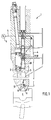
- the injection nozzle 1 shown in Fig. 1 is part of a fuel injection device, not shown as described in German patent application 196 40 085.6.
- This fuel injection device designed according to the memory injection principle is used particularly in large diesel engines, with each combustion chamber an injection nozzle 1 is provided.
- the present injection nozzle 1 has a main injection valve 2 and for the main injection a second injection valve 3 for pilot injection.
- the injection valve 3 of the pilot injection as well as its training and interaction with the other valves is the subject the description below.
- the injection nozzle 1 is connected to a storage line (common rail) 5 via a high-pressure fuel line 4.
- the storage line 5 is supplied with fuel under high pressure via a fuel pump (not shown).
- the injection valve 3 is held in the closed position as shown in FIG. 1 by the fuel pressure prevailing in the fuel line 4 - it essentially corresponds to the pressure p C present in the storage line 5 and is opened by a periodically controlled opening pressure P ⁇ .
- the injection valve 3 is designed in the so-called co-current design, i.e. the injection valve 3 opens in the direction of flow of the injected into the combustion chamber Fuel, i.e. towards the combustion chamber.
- the injection valve 3 has a Valve head 6, which in the closed position of the injector 3 in the combustion chamber opening injection openings 7 closes.
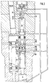
- the injection openings 7 are above a nozzle chamber 8 with the fuel line 4 in connection, so that the valve head 6 in the open position of the injection valve 3 releases the injection opening 7 and thus the pilot injection process takes place can.
- the injection valve 3 is actuated by a separately axially movable piston 10.
- the stroke of the piston 10 is limited in such a way that it determines the opening stroke of the injection valve 3.
- the piston 10 has a piston surface 11 located beyond the injection valve 3, which is acted upon in the opening interval by an opening pressure P O prevailing in an adjacent pressure chamber 12 in the opening direction of the injection valve 3, that is to say towards the combustion chamber 9.
- a pressure shoulder 13 is formed on the injection valve 3 axially between the valve head 6 and the piston 10, which points in the direction of the combustion chamber 9 and is constantly subjected to the closing pressure Ps by the fuel pressure prevailing in the nozzle chamber 8 becomes. Since the opening pressure P ⁇ and the closing pressure P s are approximately the same during the opening interval, the effective area of the pressure shoulder 13 is smaller than the piston area 11 in order to obtain a resulting pressure force F acting in the opening direction.
- the injection nozzle 1 has a 2/2-way valve 14 and a control valve 15, which are arranged coaxially with the injection valve 3 and interact in the following way:
- the coaxially between the control valve 15 and the piston 10 located 2/2-way valve 14 has a blind hole-shaped valve chamber 16 connected to the fuel line 4 and a closing member 17 axially movable therein.
- the valve chamber 16 and the pressure chamber 12 are connected to one another via a coaxial connecting line 18, the valve-side opening 19 of the connecting line 18 being closable by the needle-shaped closing head 20 of the closing element 17.
- the fuel pressure p c constantly prevailing in the valve chamber 16 acts via a pressure shoulder 21 conically formed on the closing member 17 in the opening direction of the 2/2-way valve 14 or its closing member 17.
- a piston surface 22 is formed on the end of the closing member 17 opposite the closing head 20, which acts on a closing force which is greater than the opening force acting on the pressure shoulder 21.
- the closing force periodically controlled by the control valve 15 in accordance with the injection cycle acts on the piston surface 22, which in turn on the control valve side on an axially movable Piston 23 is formed, which in turn actuates the closing member 17 in the closing direction.
- the Piston surface 22 is in turn dependent on the fuel pressure prevailing in a control line 24 acted upon, the control line 24 via a control throttle 25 to the fuel line 4th connected.
- the closing speed of the piston 23 and thus also the closing member 17 can be determined.
- the control line 24 has an outlet opening 26 which is provided by a valve member 28 of the control valve 15 is periodically opened and closed according to the injection interval.
- the drain opening 26 results in a pressure drop in the control line 24, so that the on the pressure shoulder 21 applied fuel pressure, the directional valve 14 moves in the open position and the opening pressure developing in the pressure chamber 12 is an opening of the injection nozzle 3 causes.
- the drain opening 26 is included provided a flow restrictor 28, which also causes the operating forces to operate the valve member 27 reduce. The opening and closing of the drain opening 26 thus becomes indirect the opening pressure acting on the injection nozzle 3 is triggered.
- Another throttle namely the return throttle 29, is used to influence the closing movement of the injection valve 3 is provided in a drain line 30, which during the closing movement of the injection valve 3 or its upstream piston 10, the outflow of fuel from the Pressure chamber 12 is delayed so that the closing process of the injection valve 3 is damped and thus the load on the injection valve, in particular the tensile load in the area of Valve head 6, is reduced.
- a flow throttle 31 is formed.
Landscapes
- Engineering & Computer Science (AREA)
- Chemical & Material Sciences (AREA)
- Combustion & Propulsion (AREA)
- Mechanical Engineering (AREA)
- General Engineering & Computer Science (AREA)
- Physics & Mathematics (AREA)
- Fluid Mechanics (AREA)
- Fuel-Injection Apparatus (AREA)
Applications Claiming Priority (2)
| Application Number | Priority Date | Filing Date | Title |
|---|---|---|---|
| DE19654091 | 1996-12-23 | ||
| DE19654091A DE19654091A1 (de) | 1996-12-23 | 1996-12-23 | Einspritzdüse mit in Strömungsrichtung öffnendem Einspritzventil |
Publications (1)
| Publication Number | Publication Date |
|---|---|
| EP0851118A1 true EP0851118A1 (fr) | 1998-07-01 |
Family
ID=7816065
Family Applications (1)
| Application Number | Title | Priority Date | Filing Date |
|---|---|---|---|
| EP97121399A Withdrawn EP0851118A1 (fr) | 1996-12-23 | 1997-12-05 | Buse d'injection avec soupape d'injection qui ouvre dans la direction du courant |
Country Status (2)
| Country | Link |
|---|---|
| EP (1) | EP0851118A1 (fr) |
| DE (1) | DE19654091A1 (fr) |
Cited By (2)
| Publication number | Priority date | Publication date | Assignee | Title |
|---|---|---|---|---|
| DE10000575A1 (de) * | 2000-01-10 | 2001-07-19 | Bosch Gmbh Robert | Einspritzdüse |
| EP3404235A1 (fr) * | 2017-05-19 | 2018-11-21 | Winterthur Gas & Diesel AG | Gros moteur diesel et procédé de fonctionnement d'un gros moteur diesel |
Families Citing this family (1)
| Publication number | Priority date | Publication date | Assignee | Title |
|---|---|---|---|---|
| AT501679B1 (de) * | 2006-06-29 | 2008-02-15 | Avl List Gmbh | Dämpfungseinrichtung für einen oszillierenden bauteil |
Citations (7)
| Publication number | Priority date | Publication date | Assignee | Title |
|---|---|---|---|---|
| DE2759255A1 (de) * | 1977-12-31 | 1979-07-12 | Bosch Gmbh Robert | Kraftstoffeinspritzventil fuer brennkraftmaschinen |
| US4164326A (en) * | 1978-04-06 | 1979-08-14 | General Motors Corporation | Electromagnetic fuel injector nozzle assembly |
| GB2097858A (en) * | 1981-05-05 | 1982-11-10 | Sulzer Ag | A fuel injector for an internal combustion engine |
| JPS6153455A (ja) * | 1984-08-22 | 1986-03-17 | Mitsubishi Motors Corp | 燃料噴射ノズル |
| DE4030890A1 (de) * | 1990-09-29 | 1992-04-02 | Bosch Gmbh Robert | Kraftstoffeinblaseinrichtung fuer zweitakt-brennkraftmaschinen |
| GB2284236A (en) * | 1993-11-26 | 1995-05-31 | Daimler Benz Ag | I.c. engine fuel injector |
| DE19504849A1 (de) * | 1995-02-15 | 1996-08-22 | Bosch Gmbh Robert | Kraftstoffeinspritzeinrichtung für Brennkraftmaschinen |
-
1996
- 1996-12-23 DE DE19654091A patent/DE19654091A1/de not_active Withdrawn
-
1997
- 1997-12-05 EP EP97121399A patent/EP0851118A1/fr not_active Withdrawn
Patent Citations (7)
| Publication number | Priority date | Publication date | Assignee | Title |
|---|---|---|---|---|
| DE2759255A1 (de) * | 1977-12-31 | 1979-07-12 | Bosch Gmbh Robert | Kraftstoffeinspritzventil fuer brennkraftmaschinen |
| US4164326A (en) * | 1978-04-06 | 1979-08-14 | General Motors Corporation | Electromagnetic fuel injector nozzle assembly |
| GB2097858A (en) * | 1981-05-05 | 1982-11-10 | Sulzer Ag | A fuel injector for an internal combustion engine |
| JPS6153455A (ja) * | 1984-08-22 | 1986-03-17 | Mitsubishi Motors Corp | 燃料噴射ノズル |
| DE4030890A1 (de) * | 1990-09-29 | 1992-04-02 | Bosch Gmbh Robert | Kraftstoffeinblaseinrichtung fuer zweitakt-brennkraftmaschinen |
| GB2284236A (en) * | 1993-11-26 | 1995-05-31 | Daimler Benz Ag | I.c. engine fuel injector |
| DE19504849A1 (de) * | 1995-02-15 | 1996-08-22 | Bosch Gmbh Robert | Kraftstoffeinspritzeinrichtung für Brennkraftmaschinen |
Non-Patent Citations (1)
| Title |
|---|
| PATENT ABSTRACTS OF JAPAN vol. 010, no. 216 (M - 502) 29 July 1986 (1986-07-29) * |
Cited By (2)
| Publication number | Priority date | Publication date | Assignee | Title |
|---|---|---|---|---|
| DE10000575A1 (de) * | 2000-01-10 | 2001-07-19 | Bosch Gmbh Robert | Einspritzdüse |
| EP3404235A1 (fr) * | 2017-05-19 | 2018-11-21 | Winterthur Gas & Diesel AG | Gros moteur diesel et procédé de fonctionnement d'un gros moteur diesel |
Also Published As
| Publication number | Publication date |
|---|---|
| DE19654091A1 (de) | 1998-06-25 |
Similar Documents
| Publication | Publication Date | Title |
|---|---|---|
| DE10118053A1 (de) | Ventil zum Steuern von Flüssigkeiten | |
| DE10315015A1 (de) | Kraftstoffinjektor mit Druckverstärker und Servoventil mit optimierter Steuermenge | |
| EP1774166B1 (fr) | Dispositif pour injecter du carburant dans la chambre de combustion d'un moteur a combustion interne | |
| EP1126160B1 (fr) | Injecteur pour injecter du carburant dans un moteur à combustion interne | |
| DE19716226C2 (de) | Kraftstoffeinspritzventil für Brennkraftmaschinen | |
| EP1925812B1 (fr) | Soupape d'injection de carburant pour moteurs à combustion interne | |
| EP0851118A1 (fr) | Buse d'injection avec soupape d'injection qui ouvre dans la direction du courant | |
| DE102004014198B3 (de) | Servoventil und Einspritzventil | |
| DE10160264A1 (de) | Kraftstoffeinspritzeinrichtung für eine Brennkraftmaschine | |
| DE102004010183A1 (de) | Einspritzventil | |
| DE10132248C2 (de) | Kraftstoffinjektor mit 2-Wege-Ventilsteuerung | |
| DE102005010453A1 (de) | Kraftstoffeinspritzventil für Brennkraftmaschinen | |
| EP1637727B1 (fr) | Soupape de contrôle pour un injecteur | |
| DE10042309A1 (de) | Zumessventil | |
| EP1630409A1 (fr) | Soupape servo et soupape d'injection | |
| DE10233574B4 (de) | Ventil zum Steuern von Flüssigkeiten | |
| DE102005028601B4 (de) | Einspritzventil, insbesondere Pumpe-Düse | |
| DE102004042558B4 (de) | Kraftstoffinjektor mit einer von einer Servoventileinheit gesteuerten Registerdüse | |
| DE10003252A1 (de) | Einspritzdüse | |
| DE102007001365A1 (de) | Injektor mit Steuer- und Schaltkammer | |
| DE102006036782B4 (de) | Injektor | |
| DE102005020832A1 (de) | Kraftstoffeinspritzdüse | |
| DE102004046899A1 (de) | Kraftstoffeinspritzvorrichtung | |
| DE19916965A1 (de) | Einspritzsystem | |
| DE20320383U1 (de) | Anordnung zur Steuerung eines Injektors mit einer Registerdüse sowie Injektor |
Legal Events
| Date | Code | Title | Description |
|---|---|---|---|
| PUAI | Public reference made under article 153(3) epc to a published international application that has entered the european phase |
Free format text: ORIGINAL CODE: 0009012 |
|
| AK | Designated contracting states |
Kind code of ref document: A1 Designated state(s): AT BE CH DE DK |
|
| AX | Request for extension of the european patent |
Free format text: AL;LT;LV;MK;RO;SI |
|
| AKX | Designation fees paid |
Free format text: AT CH DE GB LI |
|
| RBV | Designated contracting states (corrected) |
Designated state(s): AT CH DE GB LI |
|
| STAA | Information on the status of an ep patent application or granted ep patent |
Free format text: STATUS: THE APPLICATION IS DEEMED TO BE WITHDRAWN |
|
| 18D | Application deemed to be withdrawn |
Effective date: 19990105 |