EP0850831B1 - Inlet nose cone assembly and method for repairing the assembly - Google Patents
Inlet nose cone assembly and method for repairing the assembly Download PDFInfo
- Publication number
- EP0850831B1 EP0850831B1 EP97310273A EP97310273A EP0850831B1 EP 0850831 B1 EP0850831 B1 EP 0850831B1 EP 97310273 A EP97310273 A EP 97310273A EP 97310273 A EP97310273 A EP 97310273A EP 0850831 B1 EP0850831 B1 EP 0850831B1
- Authority
- EP
- European Patent Office
- Prior art keywords
- nose cone
- outer ring
- inlet nose
- aft fairing
- inner ring
- Prior art date
- Legal status (The legal status is an assumption and is not a legal conclusion. Google has not performed a legal analysis and makes no representation as to the accuracy of the status listed.)
- Expired - Lifetime
Links
- 238000000034 method Methods 0.000 title claims description 13
- 239000007789 gas Substances 0.000 claims description 39
- 239000002131 composite material Substances 0.000 claims description 23
- 239000000463 material Substances 0.000 claims description 19
- 239000002657 fibrous material Substances 0.000 claims description 17
- 230000032798 delamination Effects 0.000 claims description 12
- 239000011521 glass Substances 0.000 claims description 12
- 230000006835 compression Effects 0.000 claims description 9
- 238000007906 compression Methods 0.000 claims description 9
- 229920000271 Kevlar® Polymers 0.000 claims description 8
- OKTJSMMVPCPJKN-UHFFFAOYSA-N Carbon Chemical compound [C] OKTJSMMVPCPJKN-UHFFFAOYSA-N 0.000 claims description 7
- 239000000853 adhesive Substances 0.000 claims description 7
- 230000001070 adhesive effect Effects 0.000 claims description 7
- 229910052799 carbon Inorganic materials 0.000 claims description 7
- 239000003822 epoxy resin Substances 0.000 claims description 7
- 229920000647 polyepoxide Polymers 0.000 claims description 7
- 230000004044 response Effects 0.000 claims description 4
- 230000004323 axial length Effects 0.000 claims description 3
- 229920006332 epoxy adhesive Polymers 0.000 claims 2
- 239000012530 fluid Substances 0.000 claims 2
- 229920000049 Carbon (fiber) Polymers 0.000 claims 1
- 239000002313 adhesive film Substances 0.000 claims 1
- 239000004917 carbon fiber Substances 0.000 claims 1
- 230000008901 benefit Effects 0.000 description 6
- 238000013459 approach Methods 0.000 description 5
- 230000008439 repair process Effects 0.000 description 4
- 230000000712 assembly Effects 0.000 description 3
- 238000000429 assembly Methods 0.000 description 3
- 238000002485 combustion reaction Methods 0.000 description 2
- 230000007423 decrease Effects 0.000 description 2
- 230000003247 decreasing effect Effects 0.000 description 2
- 239000000203 mixture Substances 0.000 description 2
- 230000009467 reduction Effects 0.000 description 2
- 238000000926 separation method Methods 0.000 description 2
- 230000002411 adverse Effects 0.000 description 1
- 230000008859 change Effects 0.000 description 1
- 230000001934 delay Effects 0.000 description 1
- 230000000694 effects Effects 0.000 description 1
- 239000000446 fuel Substances 0.000 description 1
- 239000003365 glass fiber Substances 0.000 description 1
- 230000005484 gravity Effects 0.000 description 1
- 230000002250 progressing effect Effects 0.000 description 1
- 229920005989 resin Polymers 0.000 description 1
- 239000011347 resin Substances 0.000 description 1
- 238000005728 strengthening Methods 0.000 description 1
- 238000006467 substitution reaction Methods 0.000 description 1
Images


Classifications
-
- F—MECHANICAL ENGINEERING; LIGHTING; HEATING; WEAPONS; BLASTING
- F02—COMBUSTION ENGINES; HOT-GAS OR COMBUSTION-PRODUCT ENGINE PLANTS
- F02C—GAS-TURBINE PLANTS; AIR INTAKES FOR JET-PROPULSION PLANTS; CONTROLLING FUEL SUPPLY IN AIR-BREATHING JET-PROPULSION PLANTS
- F02C7/00—Features, components parts, details or accessories, not provided for in, or of interest apart form groups F02C1/00 - F02C6/00; Air intakes for jet-propulsion plants
- F02C7/04—Air intakes for gas-turbine plants or jet-propulsion plants
-
- F—MECHANICAL ENGINEERING; LIGHTING; HEATING; WEAPONS; BLASTING
- F02—COMBUSTION ENGINES; HOT-GAS OR COMBUSTION-PRODUCT ENGINE PLANTS
- F02K—JET-PROPULSION PLANTS
- F02K1/00—Plants characterised by the form or arrangement of the jet pipe or nozzle; Jet pipes or nozzles peculiar thereto
- F02K1/04—Mounting of an exhaust cone in the jet pipe
-
- Y—GENERAL TAGGING OF NEW TECHNOLOGICAL DEVELOPMENTS; GENERAL TAGGING OF CROSS-SECTIONAL TECHNOLOGIES SPANNING OVER SEVERAL SECTIONS OF THE IPC; TECHNICAL SUBJECTS COVERED BY FORMER USPC CROSS-REFERENCE ART COLLECTIONS [XRACs] AND DIGESTS
- Y02—TECHNOLOGIES OR APPLICATIONS FOR MITIGATION OR ADAPTATION AGAINST CLIMATE CHANGE
- Y02T—CLIMATE CHANGE MITIGATION TECHNOLOGIES RELATED TO TRANSPORTATION
- Y02T50/00—Aeronautics or air transport
- Y02T50/60—Efficient propulsion technologies, e.g. for aircraft
-
- Y—GENERAL TAGGING OF NEW TECHNOLOGICAL DEVELOPMENTS; GENERAL TAGGING OF CROSS-SECTIONAL TECHNOLOGIES SPANNING OVER SEVERAL SECTIONS OF THE IPC; TECHNICAL SUBJECTS COVERED BY FORMER USPC CROSS-REFERENCE ART COLLECTIONS [XRACs] AND DIGESTS
- Y10—TECHNICAL SUBJECTS COVERED BY FORMER USPC
- Y10T—TECHNICAL SUBJECTS COVERED BY FORMER US CLASSIFICATION
- Y10T156/00—Adhesive bonding and miscellaneous chemical manufacture
- Y10T156/10—Methods of surface bonding and/or assembly therefor
- Y10T156/1052—Methods of surface bonding and/or assembly therefor with cutting, punching, tearing or severing
- Y10T156/108—Flash, trim or excess removal
-
- Y—GENERAL TAGGING OF NEW TECHNOLOGICAL DEVELOPMENTS; GENERAL TAGGING OF CROSS-SECTIONAL TECHNOLOGIES SPANNING OVER SEVERAL SECTIONS OF THE IPC; TECHNICAL SUBJECTS COVERED BY FORMER USPC CROSS-REFERENCE ART COLLECTIONS [XRACs] AND DIGESTS
- Y10—TECHNICAL SUBJECTS COVERED BY FORMER USPC
- Y10T—TECHNICAL SUBJECTS COVERED BY FORMER US CLASSIFICATION
- Y10T29/00—Metal working
- Y10T29/49—Method of mechanical manufacture
- Y10T29/49316—Impeller making
- Y10T29/49318—Repairing or disassembling
Definitions
- This invention relates to axial flow rotary machines such as gas turbine engines, and more particularly to an inlet nose cone assembly for a gas turbine engine such as a turbofan engine.
- turbofan engine is the most widely used power plant on large aircraft today.
- a typical turbofan engine has a compression section, a combustion section and a turbine section.
- An annular, primary, flowpath for working medium gases extends axially through the compression section, combustion section and the turbine section.
- An annular, secondary flowpath is disposed radially outward of the primary flowpath.
- the compression section includes a low pressure compressor and a high pressure compressor.
- the low pressure compressor has a plurality of stages, the first stage of which is generally known as the fan stage.
- a fan duct extends circumferentially about the low pressure compressor to bound the secondary flow path.
- Working medium gases are drawn into the engine along the primary and secondary flow paths.
- the gases are passed through the fan stage and the low pressure compressor where the gases are compressed to raise the temperature and the pressure of the working medium gases.
- a portion of the gases are flowed through the secondary flowpath, inwardly of the fan duct, and do not pass through the later stages of the low pressure compressor.
- a large percentage of the thrust produced by a conventional turbofan engine is generated by the gases passing through the fan ducts.
- the ratio of gases flowing through the fan ducts to the gases flowing through the engine core is known as the bypass ratio.
- the bypass ratio may be a different value for each individual engine model according to the performance requirements of the power plant. In a large commercial turbofan engine, the bypass ratio may be as high as 6.5 to 1.
- an inlet nose cone is attached to the fan stage to gradually turn the working medium gases into the fan stage.
- the inlet nose cone is generally constructed of a light weight composite material to reduce weight, an important consideration for aircraft power plants.
- a composite inlet nose cone is known from document EP 294 654.
- An aircraft power plant such as a turbofan engine, must produce sufficient power to enable an aircraft to fly.
- the reduction of the inlet nose cone weight results in a smaller power requirement for flight.
- the inlet nose cone may cause the aft portion of the inlet nose cone, also known as the aft fairing, to radially deflect. Continuous deflections of the aft fairing can cause the composite material to delaminate or separate from adjacent layers especially if the inlet nose cone has been damaged during handling or as a result of ingesting foreign matter into the engine. These pieces of the inlet nose cone may be ingested into the primary flowpath of the engine, decreasing the overall engine performance. Delamination also decreases the effectiveness of the inlet nose cone by creating disturbances in the flow path of the working medium gases that adversely affect performance of the engine.
- One approach is to wrap a fibrous glass material around the delaminated aft fairing of the inlet nose cone. This procedure gives the inlet nose cone increased damage tolerance and added strength in the transverse direction. While this procedure repairs the damage to the inlet nose cone, it does not reduce future occurrences of delamination. The repaired inlet nose cone is still susceptible to delaminations in the future.
- Another approach is to inject resin between the separated composite layers to bond the layers back together and restore the original configuration. This procedure delays separation from progressing and bonds together the delaminated composite layers. However, delaminations may occur in the future.
- Yet another approach is to replace material in the flange and aft fairing and to provide at least one layer of fibrous kevlar® material in tension around the aft fairing to protect the fairing against handling and foreign object damage.
- This procedure repairs the damage that occurred and stiffens the aft fairing of the composite inlet nose cone and reduces stress.
- the fibrous kevlar® material exerts a tensile force upon the composite material of the aft fairing. The tensile force places stress on the bonds between the layers of the composite material and can lead to delaminations, the very problem sought to be prevented.
- This invention is in part predicated upon the recognition that a composite inlet nose cone having an aft fairing subjected to impact damage which is followed by radial deflections in the aft fairing that induce strain in that location may have separation of the adjacent layers of the composite material and subsequent loss of engine efficiency.
- an inlet nose cone formed of composite material having an aft fairing extending in cantilevered fashion from the inlet nose cone further includes a circumferentially continuous outer ring encircling the aft fairing that has a higher stiffness to mass ratio than the aft fairing to constrain the aft fairing against radial deflection.
- the present invention provides an inlet nose cone assembly as claimed in claim 1.
- the present invention provides a kit for repairing delaminations to an inlet nose cone assembly as claimed in claim 16.
- the present invention provides a method for repairing an inlet nose cone assembly as claimed in claim 17.
- an inner ring is attached to the bottom surface of the aft fairing of the inlet nose cone and the bottom surface of the outer ring.
- the outer ring is a one-piece assembly that attaches to the aft fairing of the inlet nose cone and straddles the flange.
- a primary feature of the present invention is an inlet nose cone assembly having an aft fairing. Another feature is a flange that extends radially inward from the inlet nose cone. The flange is attached to adjacent engine structure. Another feature is an outer ring encircling the aft fairing and a portion of the inlet nose cone.
- the present invention also features an inner ring constructed in the form of a frustoconical section having two surfaces. The first surface is bonded to the bottom surface of the aft fairing and the second surface is bonded to the bottom surface of the outer ring.
- a primary advantage of the present invention is the increased engine efficiency that results from a smooth flowpath for the working medium gases. Still another advantage of the present invention is a reduction in the cost of ownership of the engine that results from the enhanced durability of the composite inlet nose cone having an outer ring encircling the aft fairing. The outer ring applies a compressive force under operative conditions to the aft fairing that reduces the occurrences of delaminations and increases the durability of the inlet nose cone assembly.
- a turbofan gas turbine engine 10 is shown in perspective view.
- the engine includes a low pressure compressor 20, a high pressure compressor 25, a combustor 30, a high pressure turbine 35 and a low pressure turbine 40.
- the engine also has a primary flowpath 45 and a secondary flowpath 50 for working medium gases.
- the low pressure compressor 20 includes a fan section 55, an inner fan case 60, and an outer fan case 65.
- the inner fan case 60 extends circumferentially about the primary flowpath 45 to bound the flowpath at its outermost portion.
- the secondary flowpath 50 extends radially outward of the primary flowpath 45 through the fan section 55 and is bounded at its outermost portion by the outer fan case 65.
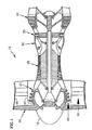
- FIG. 2 shows a cross sectional view of one embodiment of an inlet nose cone assembly 70 of the present invention.
- the assembly includes an inlet nose cone 15 having a first circumferentially extending location 80 and circumferentially located vent holes 85.
- the assembly also includes an outer ring 90, a flange 100, and an aft fairing 105.
- a bubble airseal 110 extends rearwardly, also shown in phantom is a portion of the fan section 55 that includes a fan blade 115 and a fan rotor disk 120.
- the flange 100 extends radially inward from the first circumferentially extending location 80 of the inlet nose cone 15. The flange is attached to the fan rotor disk 120.
- the aft fairing 105 is integral with the inlet nose cone 15 and extends rearwardly in cantilevered fashion from the first circumferentially extending location 80 to within close proximity of the fan rotor disk 120.
- the inlet nose cone 15 and the aft fairing 105 are composed of a composite material having a first stiffness to mass ratio.
- the bubble airseal is located under the aft fairing 105 and makes abutting contact with the fan blade 115.
- the outer ring 90 extends forward of the first circumferentially extending location 80 a first length, L 1 and rearward of the first circumferentially extending location 80 a second length L 2 to within close proximity of the fan rotor disk 120.
- the outer ring 90 completely encircles the aft fairing 105 and a portion of the inlet nose cone 15.
- the outer ring 90 is composed at least one layer of a carbon fibrous material disposed between two layers of glass fibrous material with both layers being bonded together by an epoxy resin.
- the outer ring has a second stiffness to mass ratio that is greater than the first stiffness to mass ratio of the aft fairing 105 and the inlet nose cone 15. Examples of suitable materials for this combination of materials are available from the Hexcel Corporation, Livermore, California as: T6C145 carbon fibrous material; style 120-38 glass fibrous material; and F-263 epoxy resin.
- the repaired inlet nose cone assembly includes a foreshortened aft fairing 105 that has a length L 3 that is shorter than the length of an unmodified aft fairing 105.
- the length L 2 of the outer ring is at least twice greater than the length L 3 of the aft fairing.
- the distance D 1 is the distance of the modified aft fairing from the flange end 100 and the distance D 2 is the distance of an unmodified aft fairing.
- the inlet nose cone assembly also includes an inner ring 125 in addition to the parts disclosed in FIG 2.
- the inner ring 125 is in the shape of a frustoconical section having a first part having a first surface 130 and a second part having a second surface 135.
- the inner ring has a third part 137 which is inclined outwardly from the first part to the second part such that the surfaces of the first and second parts are spaced radially one from the other and are each in faying relationship with the aft fairing and the outer ring 90.
- the first surface 130 is attached to the foreshortened aft fairing 105 and the second surface 135 is attached to the outer ring 90.
- the outer ring 90 and the inner ring 125 extend to within close proximity of the fan blade 115.
- the bubble airseal 110 rests under the first surface 130 of the inner 125.
- the inner ring 125 is composed of glass fibrous layers with an inner layer(s) of kevlar® material.
- the inner ring has a third stiffness to mass ratio that is less than the second stiffness to mass ratio of the outer ring 90. Examples of suitable materials for this combination of materials are also available from the Hexcel Corporation, Livermore, California as : style 120-38 glass fibrous material; K285 Kevlar® material; and , D-126 epoxy resin.
- working medium gases are drawn into the engine. As the gases approach the fan stage, the gases are flowed around the contour of the inlet nose cone 15. The gases are compressed in the fan section 55. A large percentage of the working medium gases are flowed into the secondary flowpath 50 and are exhausted to the atmosphere. The remainder of the working medium gases follow the primary flow path into the low pressure compressor 20 where the gases are further compressed.
- the gases then enter the high pressure compressor 25 where again the gases are compressed raising the temperature and pressure of the working medium gases.
- the gases are flowed into the combustor 30, where they are mixed with fuel and burned.
- the hot gas mixture is flowed into the high pressure turbine 35 where work is extracted from the gas mixture.
- the high pressure turbine 35 transmits this work to the high pressure compressor 25.
- the gases are then flowed into the low pressure turbine 40 where still more useful work is extracted from the gases.
- the low pressure turbine transmits work to the low pressure compressor 20 and the fan section 55. Finally the gases are exhausted to the atmosphere.
- the nose cone assembly 70 is rotated about the axis of rotation of the engine with the fan disk 120.
- the aft fairing 105 of the inlet nose cone 15 may deflect radially during engine operation in response to rotational forces in assemblies not having an outer ring. Continuous radial deflections cause the composite layers of the aft fairing 105 to delaminate if the nose cone assembly has handling or foreign object damage.
- the method for repairing this delamination is as follows. First, a portion of the trailing edge of the aft fairing 105, a length D 1 that exceeds the axial length of the delamination, is removed. Next, the surfaces of the aft fairing 105 and the inlet nose cone 15 are abraded. A bonding medium (such as EA-9394 epoxy resin adhesive available from the Dexter Corporation, Hysol Division, Pittsburg, CA 94565) is applied to the inlet nose cone 15 and the aft fairing 105.
- a bonding medium such as EA-9394 epoxy resin adhesive available from the Dexter Corporation, Hysol Division, Pittsburg, CA 94565
- the outer ring 90 is applied to the inlet nose cone 15 and the aft fairing 105 such that the outer ring 90 extends forward of the first circumferentially extending location 80 a first length, L 1 and rearward of the first circumferentially extending location 80 a second length, L 2 to within close proximity of the fan rotor disk.
- the bonding medium is allowed to cure for an appropriate amount of time.
- the bonding medium is applied to the interior surface of the outer ring 90 and the interior surface of aft fairing 105.
- the inner ring 125 is applied to the aft fairing 105 and the outer ring 90.
- the bonding medium is allowed to cure for an appropriate amount of time.
- a scrim supported epoxy resin adhesive might be used for the bonding material.
- a particular embodiment of the present invention can be utilized to modify a nose cone assembly not having an outer ring 90 but that has a serviceable inlet nose cone 15.
- the procedure entails the following steps. First, the surfaces of the inlet nose cone 15 and the aft fairing 105 are abraded. A bonding medium, such as one of those discussed previously, is applied to the surfaces of the inlet nose cone 15 and the aft fairing 105.
- the outer ring 90 is applied to the inlet nose cone 15 and the aft fairing 105 such that the outer ring 90 extends forward of the first circumferentially extending location 80 a first length, L 1, and rearward of the first circumferentially extending location 80 a second length, L 2 , to within close proximity of the fan rotor disk 120.
- the bonding medium is allowed to cure for an appropriate amount of time.
- the repair kit includes an outer ring 90 and an inner ring 125.
- the outer ring 90 is composed of a free-standing carbon fibrous and glass fibrous material combination that has a higher stiffness to mass ratio than the aft fairing 105.
- the inner ring 125 is composed of a Kevlar® fibrous and glass fibrous material combination that has a lower stiffness to mass ratio than the outer ring 90 but may be higher than the aft fairing 105. It should also be noted that material substitution could be made for the outer ring 80 and inner ring 125 provided the stiffness to mass ratios as set forth above are met. The higher stiffness to mass ratio of the outer ring 90 gives the present invention several distinct advantages.
- the higher stiffness to mass ratio enables the outer ring to constrain the radial deflections of the aft fairing 105 since the ring does not experience any significant radial deflections.
- the stiffness to mass characteristic of the outer ring 90 enables the outer ring 90 to constrain the aft fairing while having a cross sectional profile that is thin in comparison with the aft fairing 105 or the inlet nose cone 15. This is particularly important for nose cone assemblies that are modified, serviceable nose cone assemblies.
- the thin profile does not significantly change the center of gravity of the inlet nose cone assembly and thus does not significantly increase the distribution of centrifugal forces exerted on the inlet nose cone assembly.
- the thin profile of the outer ring 90 in comparison with the inlet nose cone 15 allows for a smooth flowpath around the inlet nose cone 15 and the aft fairing 105.
- Another advantage of the present invention is that the adhesive bonds of the inner ring 125 and the outer ring 90 are in compression during engine operation.
- the compressive force of the inner ring 125 results from the lower stiffness to mass ratio of the inner ring 125 in comparison with the outer ring.
- the compressive force exerted by the outer ring 90 results from the stiffness of the outer ring 90 as compared with the inlet nose cone 15 and the aft fairing 105.
- the adhesive bonds exhibit the greatest strength in compression while they exhibit the least in tension.
- the outer ring and inner ring place the bonds in a condition in which the maximum strength of the bonds can be utilized.
- the mass (or mass characteristic of a specific embodiment) may be adjusted to ensure the mass provides the necessary compressive force.
- the inner ring may or may not be circumferentially continuous. There is an advantage to having an inner ring which is circumferentially continuous.
- the stiffness to mass characteristic ensures the force stays within acceptable values over the entire range of rotational speeds which are experienced during normal operative conditions.
- the inlet nose cone and aft fairing are subjected to rotational forces and wherein the fan rotor disk grows outwardly in response to rotational forces on the fan rotor disk and exerts an outward radial force on the flange of the aft fairing.
- the outer ring extends forwardly of the first circumferentially extending location a first length, L 1 , such that the length L 1 enables the radial forces transmitted through the flange to be resisted over a distributed area.
- the outer ring also extends rearwardly of the first circumferentially extending location a second length, L 2 , to within close proximity of the fan rotor disk such that radial deflections of the aft fairing are resisted under operative conditions.
- the exterior surface of the outer ring bounds the working medium flowpath enabling the working medium gases to flow smoothly into the fan blades.
- a particular advantage of the present invention is the distribution of the radial force transmitted through the flange 100 from the fan rotor disk 120.
- the fan rotor disk 120 grows and thus applies force to the flange 100.
- the location of the outer ring 90 helps to distribute this force.
- the outer ring 90 extends forward of the first circumferentially extending location 80 a first length L 1 that is greater than the second length L 2 that extends aft of the first circumferentially extending location 80.
- the length L extends the outer ring forwardly to extend forwardly the region of resistance of the outer ring to the force which is exerted by the flange on nose cone and on the aft fairing and to decrease the force acting on the outer ring over the length L 2 through the aft fairing, decreasing the strain in the aft fairing under operative conditions.
Landscapes
- Engineering & Computer Science (AREA)
- Chemical & Material Sciences (AREA)
- Combustion & Propulsion (AREA)
- Mechanical Engineering (AREA)
- General Engineering & Computer Science (AREA)
- Structures Of Non-Positive Displacement Pumps (AREA)
- Turbine Rotor Nozzle Sealing (AREA)
Applications Claiming Priority (2)
| Application Number | Priority Date | Filing Date | Title |
|---|---|---|---|
| US08/773,041 US5833435A (en) | 1996-12-24 | 1996-12-24 | Inlet nose cone assembly and method for repairing the assembly |
| US773041 | 1996-12-24 |
Publications (3)
| Publication Number | Publication Date |
|---|---|
| EP0850831A2 EP0850831A2 (en) | 1998-07-01 |
| EP0850831A3 EP0850831A3 (en) | 1999-06-16 |
| EP0850831B1 true EP0850831B1 (en) | 2003-11-26 |
Family
ID=25097020
Family Applications (1)
| Application Number | Title | Priority Date | Filing Date |
|---|---|---|---|
| EP97310273A Expired - Lifetime EP0850831B1 (en) | 1996-12-24 | 1997-12-18 | Inlet nose cone assembly and method for repairing the assembly |
Country Status (7)
| Country | Link |
|---|---|
| US (1) | US5833435A (enExample) |
| EP (1) | EP0850831B1 (enExample) |
| JP (1) | JP4028924B2 (enExample) |
| KR (1) | KR100569764B1 (enExample) |
| DE (1) | DE69726392T2 (enExample) |
| MY (1) | MY117773A (enExample) |
| SG (1) | SG54611A1 (enExample) |
Families Citing this family (45)
| Publication number | Priority date | Publication date | Assignee | Title |
|---|---|---|---|---|
| GB9828812D0 (en) * | 1998-12-29 | 1999-02-17 | Rolls Royce Plc | Gas turbine nose cone assembly |
| US6358014B1 (en) * | 2000-03-24 | 2002-03-19 | General Electric Company | Composite spinner and method of making the same |
| GB2363170A (en) * | 2000-06-08 | 2001-12-12 | Rolls Royce Plc | Attaching a nose cone to a gas turbine engine rotor |
| GB0102169D0 (en) * | 2001-01-27 | 2001-03-14 | Rolls Royce Plc | A gas turbine engine nose cone |
| ITMI20011961A1 (it) * | 2001-09-20 | 2003-03-20 | Nuovo Pignone Spa | Flangia migliorata di accoppiamento tra compressore assiale e gruppo di dischi rotorici di alta pressione in una turbina a gas |
| KR20040016227A (ko) * | 2002-08-16 | 2004-02-21 | 한국항공우주산업 주식회사 | 항공기의 노즐 페어링 결합장치 |
| GB2398353B (en) * | 2003-02-14 | 2006-02-15 | Rolls Royce Plc | A gas turbine engine nose cone |
| US7419556B2 (en) * | 2005-10-11 | 2008-09-02 | United Technologies Corporation | Method of repair for inlet caps of turbine engines |
| DE102006011513A1 (de) * | 2006-03-10 | 2007-09-13 | Rolls-Royce Deutschland Ltd & Co Kg | Einlaufkonus aus einem Faserverbundwerkstoff für ein Gasturbinentriebwerk und Verfahren zu dessen Herstellung |
| US20100043228A1 (en) * | 2007-12-28 | 2010-02-25 | James Lloyd Daniels | Method of Preparing an Engine for Ferry Flight |
| US20100047077A1 (en) * | 2007-12-28 | 2010-02-25 | General Electric Company | Ferry Flight Engine Fairing Kit |
| US8616854B2 (en) | 2009-03-05 | 2013-12-31 | Rolls-Royce Corporation | Nose cone assembly |
| DE102009016802A1 (de) | 2009-04-09 | 2010-10-14 | Rolls-Royce Deutschland Ltd & Co Kg | Einlaufkonus aus Faserverbundmaterial für ein Gasturbinentriebwerk |
| US8322991B2 (en) | 2009-04-10 | 2012-12-04 | Rolls-Royce Corporation | Balance weight |
| US8563079B2 (en) * | 2009-06-08 | 2013-10-22 | United Technologies Corporation | Plastic welding using fiber reinforcement materials |
| GB201020213D0 (en) * | 2010-11-30 | 2011-01-12 | Rolls Royce Plc | Nose cone assembly |
| GB201020230D0 (en) * | 2010-11-30 | 2011-01-12 | Rolls Royce Plc | Nose cone assembly |
| CN102425497B (zh) * | 2011-12-07 | 2013-07-24 | 北京航空航天大学 | 燃气涡轮发动机进气锥固定结构 |
| FR2986580B1 (fr) * | 2012-02-08 | 2014-02-28 | Safran | Piece de revolution de rotor de turbomachine aeronautique |
| US9062566B2 (en) | 2012-04-02 | 2015-06-23 | United Technologies Corporation | Turbomachine thermal management |
| US9115593B2 (en) | 2012-04-02 | 2015-08-25 | United Technologies Corporation | Turbomachine thermal management |
| US9127566B2 (en) | 2012-04-02 | 2015-09-08 | United Technologies Corporation | Turbomachine thermal management |
| US9261112B2 (en) | 2012-04-24 | 2016-02-16 | General Electric Company | Dampers for fan spinners of aircraft engines |
| FR2998620B1 (fr) * | 2012-11-29 | 2018-04-06 | Safran Aircraft Engines | Capot de turbomachine apte a recouvrir un cone de soufflante |
| US9353685B2 (en) | 2012-12-21 | 2016-05-31 | United Technologies Corporation | Turbine engine nosecone with deformation region |
| US9759129B2 (en) * | 2012-12-28 | 2017-09-12 | United Technologies Corporation | Removable nosecone for a gas turbine engine |
| US9682450B2 (en) * | 2013-01-11 | 2017-06-20 | United Technologies Corporation | Gas turbine engine nose cone attachment configuration |
| WO2014120123A2 (en) | 2013-01-29 | 2014-08-07 | United Technologies Corporation | Thermoplastic nosecone for a turbine engine |
| US9969489B2 (en) * | 2013-02-08 | 2018-05-15 | General Electric Company | Hybrid spinner support |
| US9481448B2 (en) * | 2013-03-11 | 2016-11-01 | Rolls-Royce Corporation | Aerodynamic fairings secondarily attached to nosecone |
| US9482236B2 (en) | 2013-03-13 | 2016-11-01 | Rolls-Royce Corporation | Modulated cooling flow scheduling for both SFC improvement and stall margin increase |
| EP3019710A4 (en) | 2013-07-09 | 2017-05-10 | United Technologies Corporation | Plated polymer fan |
| CA2917871A1 (en) | 2013-07-09 | 2015-01-15 | United Technologies Corporation | Plated tubular lattice structure |
| WO2015017095A2 (en) * | 2013-07-09 | 2015-02-05 | United Technologies Corporation | Plated polymer nosecone |
| US10927843B2 (en) | 2013-07-09 | 2021-02-23 | Raytheon Technologies Corporation | Plated polymer compressor |
| EP3060777B1 (en) * | 2013-10-21 | 2018-12-19 | United Technologies Corporation | Fan assembly for a gas turbine engine, corresponding method of fabricating and gas turbine engine |
| US10100644B2 (en) | 2014-03-03 | 2018-10-16 | Rolls-Royce Corporation | Spinner for a gas turbine engine |
| US9657719B2 (en) * | 2014-06-16 | 2017-05-23 | General Electric Company | Ventilation arrangement |
| CN104373160B (zh) * | 2014-10-09 | 2017-01-11 | 中国石油天然气集团公司 | 一种烟气轮机的进气锥以及烟气轮机 |
| US9920708B2 (en) | 2015-02-09 | 2018-03-20 | United Technologies Corporation | Nose cone assembly and method of circulating air in a gas turbine engine |
| US10167088B2 (en) | 2015-10-19 | 2019-01-01 | General Electric Company | Crosswind performance aircraft engine spinner |
| US10207792B2 (en) * | 2016-05-23 | 2019-02-19 | United Technologies Corporation | System and method for nose cone edge delamination repair |
| US11078839B2 (en) * | 2018-01-22 | 2021-08-03 | Rolls-Royce Corporation | Composite nosecone |
| US11098646B2 (en) * | 2019-07-08 | 2021-08-24 | Pratt & Whitney Canada Corp. | Gas turbine impeller nose cone |
| US11459980B2 (en) | 2019-12-02 | 2022-10-04 | Rohr, Inc. | Compression ring for exhaust nozzle and center body attachment |
Family Cites Families (9)
| Publication number | Priority date | Publication date | Assignee | Title |
|---|---|---|---|---|
| GB543723A (en) * | 1939-11-02 | 1942-03-10 | Escher Wyss Maschf Ag | Improved means for fastening hoods to propeller hubs |
| US2401247A (en) * | 1941-09-20 | 1946-05-28 | Goodrich Co B F | Spinner assembly |
| SU372366A1 (ru) * | 1970-12-15 | 1973-03-01 | Устройство для крепления обтекателя | |
| US4957415A (en) * | 1986-04-14 | 1990-09-18 | United Technologies Corporation | Polyester composite propeller spinner and method of making same |
| DE3719098A1 (de) * | 1987-06-06 | 1988-12-22 | Mtu Muenchen Gmbh | Nasenhaube aus faserverbundwerkstoffen |
| US5252160A (en) * | 1990-11-15 | 1993-10-12 | Auto Air Composites, Inc. | Method of manufacturing a metal/composite spinner cone |
| US5149251A (en) * | 1990-11-15 | 1992-09-22 | Auto Air Composites, Inc. | Metal/composite spinner cone |
| US5307623A (en) * | 1991-05-28 | 1994-05-03 | General Electric Company | Apparatus and method for the diassembly of an ultra high bypass engine |
| US5573378A (en) * | 1995-07-10 | 1996-11-12 | United Technologies Corporation | Gas turbine nose cone attachment |
-
1996
- 1996-12-24 US US08/773,041 patent/US5833435A/en not_active Expired - Lifetime
-
1997
- 1997-12-18 DE DE69726392T patent/DE69726392T2/de not_active Expired - Lifetime
- 1997-12-18 EP EP97310273A patent/EP0850831B1/en not_active Expired - Lifetime
- 1997-12-23 KR KR1019970072440A patent/KR100569764B1/ko not_active Expired - Fee Related
- 1997-12-23 SG SG1997004651A patent/SG54611A1/en unknown
- 1997-12-23 MY MYPI97006278A patent/MY117773A/en unknown
- 1997-12-24 JP JP35432797A patent/JP4028924B2/ja not_active Expired - Fee Related
Also Published As
| Publication number | Publication date |
|---|---|
| DE69726392T2 (de) | 2004-05-27 |
| DE69726392D1 (de) | 2004-01-08 |
| EP0850831A3 (en) | 1999-06-16 |
| SG54611A1 (en) | 1998-11-16 |
| EP0850831A2 (en) | 1998-07-01 |
| JPH10196455A (ja) | 1998-07-28 |
| JP4028924B2 (ja) | 2008-01-09 |
| US5833435A (en) | 1998-11-10 |
| KR19980064500A (ko) | 1998-10-07 |
| MY117773A (en) | 2004-08-30 |
| KR100569764B1 (ko) | 2006-07-25 |
Similar Documents
| Publication | Publication Date | Title |
|---|---|---|
| EP0850831B1 (en) | Inlet nose cone assembly and method for repairing the assembly | |
| EP0834003B1 (en) | Fan blade containment assembly | |
| US5725354A (en) | Forward swept fan blade | |
| US20080159856A1 (en) | Guide vane and method of fabricating the same | |
| US5356264A (en) | Viscoelastic vibration damper for engine struts | |
| US20080159851A1 (en) | Guide Vane and Method of Fabricating the Same | |
| US20080072569A1 (en) | Guide vane and method of fabricating the same | |
| US10731662B2 (en) | Apparatus and method of manufacturing a containment case with embedded containment core | |
| US20140170435A1 (en) | Hollow airfoil with composite cover and foam filler | |
| US6394746B1 (en) | Gas turbine engine blade containment assembly | |
| GB2361747A (en) | Fan casing with radially movable liner | |
| EP2037082A1 (fr) | Dispositif d'amortissement pour aube en matériau composite | |
| JP2008157231A (ja) | 重量および振動特性を改善するシャフト及び該シャフトを備えたタービンエンジン | |
| JPH10196455A5 (enExample) | ||
| US20170096941A1 (en) | Gas turbine gearbox input shaft | |
| EP2896794B1 (en) | Blisk | |
| CN111197596A (zh) | 具有磨料尖端的复合风扇叶片 | |
| EP3084178B1 (en) | Layered ice liner | |
| US10724390B2 (en) | Collar support assembly for airfoils | |
| CN114294263A (zh) | 风扇叶盘结构及涡轮风扇发动机 | |
| US12467385B1 (en) | Outlet guide vane mount | |
| US20240288002A1 (en) | Turbomachine and method of assembly | |
| US12492641B2 (en) | Variable pitch airfoil | |
| US20240301889A1 (en) | Turbomachine and method of assembly |
Legal Events
| Date | Code | Title | Description |
|---|---|---|---|
| PUAI | Public reference made under article 153(3) epc to a published international application that has entered the european phase |
Free format text: ORIGINAL CODE: 0009012 |
|
| AK | Designated contracting states |
Kind code of ref document: A2 Designated state(s): CH DE FR GB LI |
|
| AX | Request for extension of the european patent |
Free format text: AL;LT;LV;MK;RO;SI |
|
| PUAL | Search report despatched |
Free format text: ORIGINAL CODE: 0009013 |
|
| AK | Designated contracting states |
Kind code of ref document: A3 Designated state(s): AT BE CH DE DK ES FI FR GB GR IE IT LI LU MC NL PT SE |
|
| AX | Request for extension of the european patent |
Free format text: AL;LT;LV;MK;RO;SI |
|
| 17P | Request for examination filed |
Effective date: 19991117 |
|
| AKX | Designation fees paid |
Free format text: CH DE FR GB LI |
|
| 17Q | First examination report despatched |
Effective date: 20020621 |
|
| GRAH | Despatch of communication of intention to grant a patent |
Free format text: ORIGINAL CODE: EPIDOS IGRA |
|
| GRAS | Grant fee paid |
Free format text: ORIGINAL CODE: EPIDOSNIGR3 |
|
| GRAA | (expected) grant |
Free format text: ORIGINAL CODE: 0009210 |
|
| AK | Designated contracting states |
Kind code of ref document: B1 Designated state(s): CH DE FR GB LI |
|
| REG | Reference to a national code |
Ref country code: GB Ref legal event code: FG4D |
|
| REG | Reference to a national code |
Ref country code: CH Ref legal event code: EP |
|
| REG | Reference to a national code |
Ref country code: CH Ref legal event code: NV Representative=s name: DR. R.C. SALGO EUROPEAN PATENT ATTORNEY |
|
| REF | Corresponds to: |
Ref document number: 69726392 Country of ref document: DE Date of ref document: 20040108 Kind code of ref document: P |
|
| ET | Fr: translation filed | ||
| PLBE | No opposition filed within time limit |
Free format text: ORIGINAL CODE: 0009261 |
|
| STAA | Information on the status of an ep patent application or granted ep patent |
Free format text: STATUS: NO OPPOSITION FILED WITHIN TIME LIMIT |
|
| 26N | No opposition filed |
Effective date: 20040827 |
|
| REG | Reference to a national code |
Ref country code: CH Ref legal event code: PFA Owner name: UNITED TECHNOLOGIES CORPORATION Free format text: UNITED TECHNOLOGIES CORPORATION#UNITED TECHNOLOGIES BUILDING, 1 FINANCIAL PLAZA#HARTFORD, CT 06101 (US) -TRANSFER TO- UNITED TECHNOLOGIES CORPORATION#UNITED TECHNOLOGIES BUILDING, 1 FINANCIAL PLAZA#HARTFORD, CT 06101 (US) |
|
| PGFP | Annual fee paid to national office [announced via postgrant information from national office to epo] |
Ref country code: FR Payment date: 20081205 Year of fee payment: 12 |
|
| REG | Reference to a national code |
Ref country code: FR Ref legal event code: ST Effective date: 20100831 |
|
| PG25 | Lapsed in a contracting state [announced via postgrant information from national office to epo] |
Ref country code: FR Free format text: LAPSE BECAUSE OF NON-PAYMENT OF DUE FEES Effective date: 20091231 |
|
| PGFP | Annual fee paid to national office [announced via postgrant information from national office to epo] |
Ref country code: CH Payment date: 20131212 Year of fee payment: 17 Ref country code: GB Payment date: 20131218 Year of fee payment: 17 Ref country code: DE Payment date: 20131211 Year of fee payment: 17 |
|
| REG | Reference to a national code |
Ref country code: DE Ref legal event code: R119 Ref document number: 69726392 Country of ref document: DE |
|
| REG | Reference to a national code |
Ref country code: CH Ref legal event code: PL |
|
| GBPC | Gb: european patent ceased through non-payment of renewal fee |
Effective date: 20141218 |
|
| PG25 | Lapsed in a contracting state [announced via postgrant information from national office to epo] |
Ref country code: GB Free format text: LAPSE BECAUSE OF NON-PAYMENT OF DUE FEES Effective date: 20141218 Ref country code: CH Free format text: LAPSE BECAUSE OF NON-PAYMENT OF DUE FEES Effective date: 20141231 Ref country code: DE Free format text: LAPSE BECAUSE OF NON-PAYMENT OF DUE FEES Effective date: 20150701 Ref country code: LI Free format text: LAPSE BECAUSE OF NON-PAYMENT OF DUE FEES Effective date: 20141231 |