EP0850744A2 - Process and apparatus for producing expansion-molded article - Google Patents
Process and apparatus for producing expansion-molded article Download PDFInfo
- Publication number
- EP0850744A2 EP0850744A2 EP97122605A EP97122605A EP0850744A2 EP 0850744 A2 EP0850744 A2 EP 0850744A2 EP 97122605 A EP97122605 A EP 97122605A EP 97122605 A EP97122605 A EP 97122605A EP 0850744 A2 EP0850744 A2 EP 0850744A2
- Authority
- EP
- European Patent Office
- Prior art keywords
- foamed particles
- compression
- heated steam
- super heated
- feeding region
- Prior art date
- Legal status (The legal status is an assumption and is not a legal conclusion. Google has not performed a legal analysis and makes no representation as to the accuracy of the status listed.)
- Granted
Links
Images


Classifications
-
- B—PERFORMING OPERATIONS; TRANSPORTING
- B29—WORKING OF PLASTICS; WORKING OF SUBSTANCES IN A PLASTIC STATE IN GENERAL
- B29C—SHAPING OR JOINING OF PLASTICS; SHAPING OF MATERIAL IN A PLASTIC STATE, NOT OTHERWISE PROVIDED FOR; AFTER-TREATMENT OF THE SHAPED PRODUCTS, e.g. REPAIRING
- B29C44/00—Shaping by internal pressure generated in the material, e.g. swelling or foaming ; Producing porous or cellular expanded plastics articles
- B29C44/20—Shaping by internal pressure generated in the material, e.g. swelling or foaming ; Producing porous or cellular expanded plastics articles for articles of indefinite length
- B29C44/30—Expanding the moulding material between endless belts or rollers
-
- B—PERFORMING OPERATIONS; TRANSPORTING
- B29—WORKING OF PLASTICS; WORKING OF SUBSTANCES IN A PLASTIC STATE IN GENERAL
- B29C—SHAPING OR JOINING OF PLASTICS; SHAPING OF MATERIAL IN A PLASTIC STATE, NOT OTHERWISE PROVIDED FOR; AFTER-TREATMENT OF THE SHAPED PRODUCTS, e.g. REPAIRING
- B29C44/00—Shaping by internal pressure generated in the material, e.g. swelling or foaming ; Producing porous or cellular expanded plastics articles
- B29C44/34—Auxiliary operations
- B29C44/3415—Heating or cooling
-
- B—PERFORMING OPERATIONS; TRANSPORTING
- B29—WORKING OF PLASTICS; WORKING OF SUBSTANCES IN A PLASTIC STATE IN GENERAL
- B29C—SHAPING OR JOINING OF PLASTICS; SHAPING OF MATERIAL IN A PLASTIC STATE, NOT OTHERWISE PROVIDED FOR; AFTER-TREATMENT OF THE SHAPED PRODUCTS, e.g. REPAIRING
- B29C44/00—Shaping by internal pressure generated in the material, e.g. swelling or foaming ; Producing porous or cellular expanded plastics articles
- B29C44/34—Auxiliary operations
- B29C44/36—Feeding the material to be shaped
- B29C44/38—Feeding the material to be shaped into a closed space, i.e. to make articles of definite length
- B29C44/44—Feeding the material to be shaped into a closed space, i.e. to make articles of definite length in solid form
- B29C44/445—Feeding the material to be shaped into a closed space, i.e. to make articles of definite length in solid form in the form of expandable granules, particles or beads
-
- B—PERFORMING OPERATIONS; TRANSPORTING
- B29—WORKING OF PLASTICS; WORKING OF SUBSTANCES IN A PLASTIC STATE IN GENERAL
- B29C—SHAPING OR JOINING OF PLASTICS; SHAPING OF MATERIAL IN A PLASTIC STATE, NOT OTHERWISE PROVIDED FOR; AFTER-TREATMENT OF THE SHAPED PRODUCTS, e.g. REPAIRING
- B29C44/00—Shaping by internal pressure generated in the material, e.g. swelling or foaming ; Producing porous or cellular expanded plastics articles
- B29C44/34—Auxiliary operations
- B29C44/36—Feeding the material to be shaped
- B29C44/46—Feeding the material to be shaped into an open space or onto moving surfaces, i.e. to make articles of indefinite length
- B29C44/54—Feeding the material to be shaped into an open space or onto moving surfaces, i.e. to make articles of indefinite length in the form of expandable particles or beads
-
- B—PERFORMING OPERATIONS; TRANSPORTING
- B29—WORKING OF PLASTICS; WORKING OF SUBSTANCES IN A PLASTIC STATE IN GENERAL
- B29C—SHAPING OR JOINING OF PLASTICS; SHAPING OF MATERIAL IN A PLASTIC STATE, NOT OTHERWISE PROVIDED FOR; AFTER-TREATMENT OF THE SHAPED PRODUCTS, e.g. REPAIRING
- B29C44/00—Shaping by internal pressure generated in the material, e.g. swelling or foaming ; Producing porous or cellular expanded plastics articles
- B29C44/34—Auxiliary operations
- B29C44/60—Measuring, controlling or regulating
-
- B—PERFORMING OPERATIONS; TRANSPORTING
- B29—WORKING OF PLASTICS; WORKING OF SUBSTANCES IN A PLASTIC STATE IN GENERAL
- B29C—SHAPING OR JOINING OF PLASTICS; SHAPING OF MATERIAL IN A PLASTIC STATE, NOT OTHERWISE PROVIDED FOR; AFTER-TREATMENT OF THE SHAPED PRODUCTS, e.g. REPAIRING
- B29C44/00—Shaping by internal pressure generated in the material, e.g. swelling or foaming ; Producing porous or cellular expanded plastics articles
- B29C44/34—Auxiliary operations
- B29C44/3415—Heating or cooling
- B29C44/3426—Heating by introducing steam in the mould
-
- B—PERFORMING OPERATIONS; TRANSPORTING
- B29—WORKING OF PLASTICS; WORKING OF SUBSTANCES IN A PLASTIC STATE IN GENERAL
- B29K—INDEXING SCHEME ASSOCIATED WITH SUBCLASSES B29B, B29C OR B29D, RELATING TO MOULDING MATERIALS OR TO MATERIALS FOR MOULDS, REINFORCEMENTS, FILLERS OR PREFORMED PARTS, e.g. INSERTS
- B29K2023/00—Use of polyalkenes or derivatives thereof as moulding material
- B29K2023/04—Polymers of ethylene
- B29K2023/06—PE, i.e. polyethylene
-
- B—PERFORMING OPERATIONS; TRANSPORTING
- B29—WORKING OF PLASTICS; WORKING OF SUBSTANCES IN A PLASTIC STATE IN GENERAL
- B29K—INDEXING SCHEME ASSOCIATED WITH SUBCLASSES B29B, B29C OR B29D, RELATING TO MOULDING MATERIALS OR TO MATERIALS FOR MOULDS, REINFORCEMENTS, FILLERS OR PREFORMED PARTS, e.g. INSERTS
- B29K2023/00—Use of polyalkenes or derivatives thereof as moulding material
- B29K2023/10—Polymers of propylene
- B29K2023/12—PP, i.e. polypropylene
-
- B—PERFORMING OPERATIONS; TRANSPORTING
- B29—WORKING OF PLASTICS; WORKING OF SUBSTANCES IN A PLASTIC STATE IN GENERAL
- B29K—INDEXING SCHEME ASSOCIATED WITH SUBCLASSES B29B, B29C OR B29D, RELATING TO MOULDING MATERIALS OR TO MATERIALS FOR MOULDS, REINFORCEMENTS, FILLERS OR PREFORMED PARTS, e.g. INSERTS
- B29K2105/00—Condition, form or state of moulded material or of the material to be shaped
- B29K2105/04—Condition, form or state of moulded material or of the material to be shaped cellular or porous
- B29K2105/048—Expandable particles, beads or granules
Definitions
- the present invention relates to methods and apparatus for producing expansion-molded articles.
- the continuous molding process has the advantages of permitting the continuous production of molded articles from foamed particles and the provision of molded articles of continuous length compared with the batch type molding process.
- the steam heating method is a method useful even for the foamed particles of the polyolefin resin.
- an attempt to mold the foamed particles of the polyolefin resin by the continuous molding process using such steam heating as described in Japanese Patent Publication No. 2424/1977 has involved such problems that steam for heating the foamed particles leaks out on the feeding side of the foamed particles to cause failures in fusion bonding among the foamed particles and in secondary expansion of the foamed particles due to insufficient heating, and that when the leakage of the steam becomes greater, the foamed particles fed come to flow backward on the feeding side.
- the reason for this is considered to be attributable to a difference in secondary expandability between the foamed particles of the polystyrene resin and the foamed particles of the polyolefin resin. More specifically, the foamed particles of the polystyrene resin undergo secondary expansion at a relatively low temperature (generally, 100°C or lower) because the polystyrene resin is noncrystalline and has good retention of a foaming agent used in the preparation of the foamed particles, and so the foamed particles contain about several percent of the foaming agent.
- the polyolefin resin is crystalline, and a foaming agent used in the preparation of the foamed particles thereof escapes out of the particles in a relatively short period of time. Therefore, in order to secondarily expand the foamed particles of the polyolefin resin, it is necessary to heat the foamed particles at a temperature higher than the case of the foamed particles of the polystyrene resin. It is thus not easy to secondarily expand the foamed particles of the polyolefin resin to such an extent that the leakage of the steam can be prevented before they reach the heating region. In addition, the secondary expansion of the foamed particles of the polyolefin resin requires to feed high-pressure steam.
- the process (1) has involved a problem that since the foamed particles are heated in the state that they have been compressed to a bulk volume of 40-70% on the original bulk volume, the resulting molded article comes to have an expansion ratio greatly lowered compared with the expansion ratio of the original foamed particles.
- the degree of reduction in expansion ratio of the resulting molded article is smaller than that of the process (1) because the foamed particles the internal pressure of which has been raised is used, and so it is possible to control the reduction in expansion ratio of the molded article compared with the expansion ratio of the original foamed particles to substantially the same degree as that of the molded article obtained by the batch type molding process.
- the process (2) requires to apply an internal pressure considerably higher than the batch type molding process to foamed particles. When the foamed particles to which such a high internal pressure has been applied are used, it takes a longer time to cool the resulting molded article.
- the present invention has been completed in view of the foregoing circumstances, and has as its object the provision of methods and apparatus for producing expansion-molded articles, by which in continuous molding of foamed particles of a polyolefin resin, the degree of reduction in expansion ratio of the resulting molded article compared with the expansion ratio of the original foamed particles can be made small without applying a high internal pressure to the foamed particles, and at the same time the time required to cool the molded article can be shortened, so that the line speed in the molding can be increased to improve productivity.
- an apparatus for continuously producing an expansion-molded article by feeding foamed particles between a belt continuously traveling along the upper surface within a passageway defined by structural members and having a rectangular form in section and a belt continuously traveling along the lower surface within the passageway, and then causing the foamed particles to successively pass through a super heated steam-feeding region and a cooling region within the passageway, characterized in that a compressing means for compressing the foamed particles and a compression-releasing means for removing a part or the whole of the compression are provided within the passageway on the upstream side of the super heated steam-feeding region.
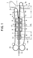
- Fig. 1 is a schematic drawing of a molding apparatus illustrating an embodiment of a method according to the present invention.
- Fig. 2 is a cross-sectional view of principal parts illustrating an embodiment of a method for conducting compression of foamed particles and release from the compression.
- Fig. 3 is a cross-sectional view of principal parts illustrating another embodiment of a method for conducting compression of foamed particles and release from the compression.
- Fig. 4 is a cross-sectional view of principal parts illustrating a further embodiment of a method for conducting compression of foamed particles and release from the compression.
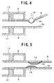
- Fig. 5 is a cross-sectional view of principal parts illustrating a still further embodiment of a method for conducting compression of foamed particles and release from the compression.
- Fig. 6 is a cross-sectional view of principal parts illustrating a yet still further embodiment of a method for conducting compression of foamed particles and release from the compression.
- Fig. 7 is a cross-sectional view of principal parts illustrating a yet still further embodiment of a method for conducting compression of foamed particles and release from the compression.
- the resin which forms the foamed particles useful in the practice of the present invention is a polyolefin resin, which is composed of a homopolymer of an ⁇ -olefin component such as ethylene, propylene or 1-butene, a copolymer containing at least 50 wt.% of such an ⁇ -olefin component or a mixture of at least two of these homopolymers and copolymers, or a mixture composed of such a polyolefin resin and any other resin than the polyolefin resin and/or a synthetic rubber and comprising at least 50 wt.% of the ⁇ -olefin component.
- the resins are used as uncrosslinked or in a crosslinked state.
- the foamed particles of the polyolefin resin used in the present invention are preferably those having a bulk density of 0.09-0.006 g/cm 3 or those formed of an uncrosslinked polypropylene resin or uncrosslinked polyethylene resin as a base resin and having two endothermic peaks on a DSC curve obtained by their differential scanning calorimetry (see Japanese Patent Publication Nos. 44779/1988 and 39501/1995).
- the DSC curve means a DSC curve obtained when 0.5-4 mg of a foamed particle sample is heated from room temperature to 220°C at a heating rate of 10°C/min by means of a differential scanning calorimeter to measure it.
- the foamed particles formed of an uncrosslinked polypropylene resin or uncrosslinked polyethylene resin as a base resin and having two endothermic peaks on the DSC curve thereof have an effect of providing a molded article having excellent surface smoothness, dimensional stability and mechanical strength compared with those not having two endothermic peaks on the DSC curve thereof.
- the polypropylene resin means a resin, which is composed of a propylene homopolymer, a copolymer containing at least 50 wt.% of a propylene component or a mixture of at least two of these homopolymers and copolymers, or a mixture composed of such a polypropylene resin and any other resin than the polypropylene resin and/or a synthetic rubber and comprising at least 50 wt.% of the propylene component.
- the polyethylene resin means a resin, which is composed of an ethylene homopolymer, a copolymer containing at least 50 wt.% of an ethylene component or a mixture of at least two of these homopolymers and copolymers, or a mixture composed of such a polyethylene resin and any other resin than the polyethylene resin and/or a synthetic rubber and comprising at least 50 wt.% of the ethylene component.
- Recovery factor from compression (%) V 2 /V 1 x 100 wherein V 1 is the original bulk volume of the foamed particles, and V 2 is a bulk volume of the foamed particles measured upon elapsed time of 10 seconds after the foamed particles are compressed to a bulk volume of 60% on the original bulk volume, and the compressive force is then removed, is at least 80%, preferably at least 85%.
- the foamed particles of the polyolefin resin used in the present invention can be prepared by, for example, a process in which particles of a polyolefin resin and a foaming agent are dispersed in water in a closed vessel, the resultant dispersion is heated to a temperature not lower than the softening point of the resin particles to impregnate the resin particles with the foaming agent, and the resin particles and water are then released into an atmosphere of a pressure lower than the internal pressure of the vessel, thereby expanding the resin particles.
- the foamed particles having a high closed cell content can be easily obtained by, for example, expanding resin particles so as to form foamed particles having two endothermic peaks on a DSC curve thereof as described above. However, they may also be obtained by other methods. In the present invention, it is however preferable to use the foamed particles having a high closed cell content formed so as to have two endothermic peaks on a DSC curve thereof.
- the bulk density of the foamed particles and the kind of the base resin of the foamed particles are important second to the closed cell content as factors for imparting a high recovery factor from compression to the foamed particles.
- the bulk density of the foamed particles In order to impart the high recovery factor from compression, it is preferable to control the bulk density of the foamed particles to 0.09-0.006 g/cm 3 and to select a polypropylene resin or polyethylene resin as the base resin.
- the kind of a foaming agent used and a foaming temperature may be mentioned as other factors which may slightly affect the recovery factor from compression of the foamed particles.
- the foamed particles of the polyolefin resin which are used as a raw material in the method of the present invention, may be those to which an internal pressure higher than the atmospheric pressure has been applied by subjecting them to a pressurizing treatment with air or the like.
- foamed particles of a polyolefin resin which have an internal pressure substantially equal to the atmospheric pressure, may also be used in the method of the present invention.
- the foamed particles the internal pressure of which has been increased it is preferable to use those having an internal pressure of 2.5 atm or lower.
- the step of the pressurizing treatment for applying the internal pressure to the particles and the equipment therefor become useless. As a result, it is possible to reduce production cost to a great extent.
- No particular limitation is imposed on the weight of each of the foamed particles used. However, those having an average particle weight of about 0.5-5 mg are generally used.
- Fig. 1 illustrates an exemplary molding apparatus used for practicing the method for continuously molding the foamed particles of the polyolefin resin according to the present invention.
- reference characters A, B, C and S designate a foamed particle-feeding region, a molded article-cooling region, a passageway through which the foamed particles and molded article are transferred, and a super heated steam-feeding region, respectively.
- the molding apparatus includes a hopper 1 in which the foamed particles are stored, an endless belt 3 traveling between upper rolls 2a and 2b, and an endless belt 5 traveling between lower rolls 4a and 4b, and is so constructed that the foamed particles 11 of the polyolefin resin fed to the feeding region A from the hopper 1 are held between the endlessly traveling upper and lower belts 3 and 5 to cause them to pass through the passageway C, during which they are heated with steam to mutually fusion-bond the foamed particles, thereby obtaining a molded article.
- reference numeral 18 in Fig. 1 indicates a support.
- the upper roll 2a and the lower roll 4a are driven to rotate on their axes, while the upper roll 2b and the lower roll 4b do not rotate. Therefore, the upper belt 3 and the lower belt 5 are constructed so as to travel slidably on the rolls 2b and 4b, respectively.
- a lubricant such as polytetrafluoroethylene (Teflon) is provided on the rolls 2b and 4b at their surfaces with which the respective belts come into contact, so as to enhance the slidability of the belts.
- the upper roll 2b is so constructed that it can be vertically moved by a moving means (not illustrated) and that the inclination angle of the upper belt 3 in the foamed particle-feeding region A can be varied by shifting the position of the upper roll 2b.
- Reference numeral 6 indicates an auxiliary press plate and is so constructed that when the inclination angle of the upper belt 3 is adjusted by vertically moving the upper roll 2b, the inclination angle of the auxiliary press plate 6 can be varied together with the belt 3.
- the foamed particles 11 of the polyolefin resin fed from the hopper 1 can be compressed while they are being transferred on the downstream side.
- the compressed foamed particles are fed to the passageway C having a space of a substantially rectangular form in section defined by upper and lower thickness-regulating plates 7 and 8 and width-regulating plates (not expressly illustrated) provided over between their corresponding sides of the thickness-regulating plates 7 and 8.
- the upper and lower belts 3 and 5 are so constructed that they travel with the lower part 3a of the upper belt 3 and the upper part 5a of the lower belt 5 coming into contact with the thickness-regulating plates 7 and 8, respectively, in passageway C.
- the thickness-regulating plates 7 and 8 and the auxiliary press plate 6 are composed of a metal plate such as an aluminum plate, and a lubricant composed of polytetrafluoroethylene or the like is fixed to their surfaces, with which the respective belts 3 and 5 come into contact, so as to improve the slidability of the belts 3 and 5.
- the present invention is not limited to the case where the endlessly traveling belts may be provided only on the upper and lower sides, and so they may also be provided on both lateral sides. When no endlessly traveling belt is provided on both lateral sides, for example, the resulting molded article is transferred sliding on the surfaces of the width-regulating plates and the like within the passageway C.
- the endlessly traveling belts are also provided on both lateral sides, however, there is no possibility that the molded article may come into contact with the surfaces of the width-regulating plates and the like, so that the form and appearance of sides of the resulting molded article can be improved.
- a projection 13 is provided on each of upper and lower sides near the entrance to the passageway C.
- the foamed particles are compressed to the utmost at the time they have reached the top of the projection.
- the foamed particles are preferably compressed to a bulk volume of 10-60% (the proportion of this compression will hereinafter be referred to as "compression ratio") on the bulk volume of the original foamed particles (uncompressed foamed particles). It is particularly preferable to compress them to a compression ratio of 15-50%.
- the compression ratio of the foamed particles can be controlled by changing the height of the projection 13 or/and changing the inclination angle of the upper belt 3.
- the foamed particles are compressed to a compression ratio lower than 10% (excess of compression), there is a possibility that the cells in the foamed particles may be broken, resulting in impossibility of molding, or that a load applied to the apparatus by the compression may be increased. If the foamed particles are compressed to a compression ratio higher than 60% (insufficiency of compression), there is a possibility that seal of steam may become insufficient, so that heating steam leaks out on the feeding side of the foamed particles to cause insufficient heating of the particles, resulting in a failure to provide a satisfactory molded article, or that the foamed particles fed may be caused to flow backward on the feeding side by the steam leaked, resulting in impossibility of molding.
- the projection 13 may be provided on either of the upper and lower sides or on both upper and lower sides.
- a lubricant composed of polytetrafluoroethylene or the like is provided on the projection 13 at its surface with which the belt 3 or 5 comes into contact, or the whole of the projection 13 is formed with polytetrafluoroethylene or the like.
- the inclination angle of the upper belt 3 is preferably adjusted to 10° or narrower, more preferably 1-5°. If the foamed particles are compressed to such a quick extent that the inclination angle of the upper belt 3 is wider than 10°, the particles tend to be returned in a direction of the hopper due to the rebounding force of the particles compressed. As a result, the desired compression ratio cannot be achieved. In order to smoothly compress the foamed particles, it is preferable for the above-described reason to control the inclination angle of the upper belt 3 narrower. However, the narrower the inclination angle, the longer the length of the apparatus. It is therefore desirable that the inclination angle be suitably selected within the range in which the particles are not returned to the hopper.
- the foamed particles transferred by holding them between the belts 3 and 5 are compressed to the utmost at the time they have reached the top of the projection 13. After passing through the top of the projection 13, the foamed particles are released from a part or the whole of the compression.
- the foamed particle from which a part or the whole of the compression has been released are heated with steam jetted out within the passageway C from steam-feeding sections 17 in the super heated steam-feeding region S as they are held between the belts 3 and 5. Therefore, the belts 3 and 5 must have good permeability to steam.
- a belt obtained by boring a great number of through-holes each having a diameter of 0.5-3.0 mm at a pitch of about 10-50 mm in a stainless steel belt having a thickness of about 0.2- 1.0 mm.
- the super heated steam-feeding region S includes the steam-feeding sections 17 for heating the foamed particles 11 with steam to mold them and sucking sections 9 for sucking the heating steam and drain of the steam under reduced pressure on both upstream and downstream sides of the super heated steam-feeding region S.
- the provision of the sucking sections 9 to conduct suction permits preventing the drain from standing in the passageway to inhibit the feed of the foamed particles (particularly, the action of the sucking sections 9 on the upstream side of the super heated steam-feeding region S), and preventing the cooling effect on the molded article from being lowered due to the drain to cause warpage on the resulting molded article (particularly, the action of the sucking sections 9 on the downstream side of the super heated steam-feeding region S).
- the present invention is not limited only to the case where the sucking sections 9 are provided at both upper and lower parts of the passageway, and so they may be provided only at lower parts of the passageway for the purpose of removing drain standing on the lower side of the passageway.
- the apparatus according to the present invention is so constructed that the heating steam fed from the steam-feeding sections 17 is fed within the passageway C through the through-holes bored in the thickness-regulating plates 7 and 8 and the through-holes bored in the belts 3 and 5.
- the pressure of the heating steam fed from the steam-feeding sections 17 is generally 1.0-4.0 kg/cm 2 G.
- the foamed particles heated with the steam expand so as to close interparticle spaces within the passageway C, and undergo mutual fusion bonding to form a molded article (although it cannot be said to be a complete molded article at this time, it is called a molded article for the sake of convenience because the foamed particles have been mutually fusion-bonded).
- the molded article is then transferred to the cooling region B equipped with a cooling means 10 to cool it.
- a cooling means 10 for example, a cooling plate, in which a cooling water circulating pipe is built, is used.
- the above-described steps are continuously and repeatedly conducted to obtain a molded article 12 of continuous length.
- the sucking sections 9, steam-feeding sections 17 and cooling means 10 are may be provided not only on the sides of the thickness-regulating plates 7 and 8, but also on the sides of the width-regulating plates though not expressly illustrated.
- the area of a section of the passageway C perpendicular to the direction, in which the foamed particles are transferred be kept substantially constant on the downstream side from the starting point of the super heated steam-feeding region S until the molded article is fully cooled. If the molded article is compressed on the downstream side from the starting point of the super heated steam-feeding region S (the sectional area of the space within the passageway on the downstream side from the super heated steam-feeding region S is made narrower) before the molded article is fully cooled, a mark such as a flow mark is left on the surface of the resulting molded article 12, so that the surface appearance of the molded article 12 is deteriorated.
- the term "the molded article is fully cooled” means that the molded article is cooled to such a low temperature that it undergoes no substantial expansion.
- the apparatus is so constructed that the projection 13 is provided on each of the upper and lower sides near the entrance to the passageway C, and the foamed particles transferred by holding them between the belts 3 and 5 are compressed to the utmost at the time they have reached the top of the projection 13, and released from a part or the whole of the compression by transferring them on the downstream side from the top of the projection 13.
- the projection 13 may be provided at an optional position between the vicinity of the entrance to the passageway C and the starting point of the super heated steam-feeding region S.
- the projection 13 may not be necessarily provided at two positions of the upper and lower sides, but may be provided at only one position of the upper or lower side.
- the form of the projection 13 is not limited to such a trapezoid as illustrated, and so the projection 13 may be in any form.
- the apparatus is so constructed that the foamed particles are compressed to the utmost at the time they have reached the top of the projection 13, and released from the compression after passing through the top of the projection 13.
- each of the belts 3 and 5 can be pressed by a plurality of vertically movable press rolls 14 as illustrated in Fig. 3, so as to conduct the utmost compression of the foamed particles and their release from the compression by the press rolls 14.
- the apparatus may be so constructed that only the upper belt 3 is pressed by a press roll 14 as illustrated in Fig. 4. When the belts 3 and 5 (or only the belt 3) are pressed by the press rolls or roll 14 as illustrated in Fig.
- a projection 13 may also be provided on each of the upper and lower sides near the entrance to the passageway C with the positions of the projections staggered as illustrated in Fig. 5.
- the projections 13 are provided with their positions staggered as described above, the foamed particles can be not only smoothly compressed to the utmost at the time they have reached the top of the projection 13, but also smoothly released from the compression.
- a plurality of projections 13 are alternately provided on the upper and lower sides in such a manner that the height of the projection becomes lower toward the direction of the passageway C from the direction of the foamed particle-feeding region A as illustrated in Fig.
- the foamed particles compressed can be more smoothly released from the compression.
- a plurality of projections 13 are alternately provided on the upper and lower sides in such a manner that the height of the projection becomes higher toward the direction of the passageway C from the direction of the foamed particle-feeding region A though not expressly illustrated, the foamed particles can be more smoothly compressed.
- both compression of the foamed particles and their release from the compression can be more smoothly conducted.
- Fig. 7 illustrates another embodiment for conducting the compression of the foamed particles.
- the foamed particles 11 are compressed by a screw feeder 15 so constructed that its screw pitch becomes narrower toward the tip.
- the release from the compression of the foamed particles compressed by the screw feeder 15 can be conducted by, for example, providing inclined plates 16 in such a manner that the space becomes wider toward the direction of the passageway C.
- the foamed particles are compressed by both inclined belt and projection as described above, but also, though not expressly illustrated, a method in which the foamed particles are compressed only by holding them between inclined belts to transfer them, and then released from the compression by providing inclined plates in such a manner that the space becomes wider toward the direction of the passageway C, may be used.
- Foamed particles shown in Table 1 were compressed in the same apparatus (dimensions of passageway C were fixed as follows: width between the position just after passed through the projections and the exit of the molded article from the cooling region B: 300 mm; height therebetween: 25 mm) as that illustrated in Fig. 1 so as to give a compression ratio shown in Table 1, and then released from the compression so as to give a release factor from compression shown in Table 1 (using projections of the type illustrated in Fig. 2).
- the thus-treated foamed particles were heated with heating steam while transferring them through the super heated steam-feeding region S by holding them between the belts 3 and 5.
- the line speed and steam pressure in the molding are shown collectively in Table 1.
- suction under reduced pressure was performed in the sucking sections 9 situated at the upstream and downstream sides of the super heated steam-feeding region.
- Molding was conducted by using an apparatus having no compression-releasing means (i.e. an apparatus having no projection) and foamed particles having the same bulk density as in Example 1 and selecting molding conditions in such a manner that a molded article having the same density as that obtained in Example 1 can be provided.
- the properties of the foamed particles used, molding conditions and the properties of the molded article obtained are shown collectively in Table 1.
- Foamed particles shown in Table 2 were compressed in the same apparatus (dimensions of passageway C were fixed as follows: width between the position just after passed through the projections and the exit of the molded article from the cooling region B: 300 mm; height therebetween: 25 mm) as that illustrated in Fig. 1 so as to give a compression ratio shown in Table 2, and then released from the compression so as to give a release factor from compression shown in Table 2 (using projections of the type illustrated in Fig. 2).
- the thus-treated foamed particles were heated with heating steam while transferring them through the super heated steam-feeding region S by holding them between the belts 3 and 5.
- the line speed and steam pressure in the molding are shown collectively in Table 2.
- suction under reduced pressure was performed in the sucking sections 9 situated at the upstream and downstream sides of the super heated steam-feeding region.
- Molding was conducted by using an apparatus having no compression-releasing means (i.e. an apparatus having no projection) and foamed particles having the same bulk density and internal pressure as in Example 2 and selecting other molding conditions in such a manner that a molded article of good quality can be provided when the molding is conducted at the same line speed as in Example 2.
- the properties of the foamed particles used, molding conditions and the properties of the molded article obtained are shown collectively in Table 2.
- Foamed particles shown in Table 3 were compressed in the same apparatus (dimensions of passageway C were fixed as follows: width between the position just after passed through the projections and the exit of the molded article from the cooling region B: 300 mm; height therebetween: 25 mm) as that illustrated in Fig. 1 so as to give a compression ratio shown in Table 3, and then released from the compression so as to give a release factor from compression shown in Table 3 (using projections of the type illustrated in Fig. 2).
- the thus-treated foamed particles were heated with heating steam while transferring them through the super heated steam-feeding region S by holding them between the belts 3 and 5.
- the line speed and steam pressure in the molding are shown collectively in Table 3. In this example, suction under reduced pressure was performed in the sucking sections 9 situated at the upstream and downstream sides of the super heated steam-feeding region.
- Foamed particles shown in Table 4 were compressed in the same apparatus (dimensions of passageway C were fixed as follows: width between the position just after passed through the projections and the exit of the molded article from the cooling region B: 300 mm; height therebetween: 25 mm) as that illustrated in Fig. 1 so as to give a compression ratio shown in Table 4, and then released from the compression so as to give a release factor from compression shown in Table 4 (using projections of the type illustrated in Fig. 2).
- the thus-treated foamed particles were heated with heating steam while transferring them through the super heated steam-feeding region S by holding them between the belts 3 and 5.
- the line speed and steam pressure in the molding are shown collectively in Table 4. In this example, suction under reduced pressure was performed in the sucking sections 9 situated at the upstream and downstream sides of the super heated steam-feeding region.
- Molding was conducted by using an apparatus having no compression-releasing means (i.e. an apparatus having no projection) and the same foamed particles as those used in Example 4 and selecting other molding conditions in such a manner that a molded article of good quality can be provided when the molding is conducted at the same line speed as in Example 4.
- the properties of the foamed particles used, molding conditions and the properties of the molded article obtained are shown collectively in Table 4.
- the methods of the present invention have the following excellent effects compared with the conventional methods for producing expansion-molded articles by continuously molding foamed particles of a polyolefin resin.
Abstract
Description


Claims (18)
- A method for continuously producing an expansion-molded article, which comprises feeding foamed particles between a belt continuously traveling along the upper surface within a passageway defined by structural members and having a rectangular form in section and a belt continuously traveling along the lower surface within the passageway, and then causing the foamed particles to successively pass through a super heated steam-feeding region and a cooling region within the passageway, characterized in that the foamed particles used are foamed particles of a polyolefin resin, in which a recovery factor from compression defined by the following equation (1):
- The method according to Claim 1, wherein the foamed particles are compressed to a bulk volume of 10-60% on the original bulk volume on the upstream side of the super heated steam-feeding region.
- The method according to Claim 1, wherein the compression applied to the foamed particles on the upstream side of the super heated steam-feeding region is removed in such a manner that a release factor from compression defined by the following equation (2):
- The method according to Claim 1, wherein the area of a section of the passageway perpendicular to the direction, in which the foamed particles are transferred, is kept substantially constant on the downstream side from the starting point of the super heated steam-feeding region until the molded article is fully cooled.
- The method according to Claim 1, wherein steam or/and drain within the passageway are sucked under reduced pressure on the upstream side of the super heated steam-feeding region, or on both upstream and downstream sides of the super heated steam-feeding region.
- The method according to Claim 1, wherein the bulk density of the foamed particles of the polyolefin resin as a raw material is 0.09-0.006 g/cm3.
- The method according to Claim 1, wherein the foamed particles of the polyolefin resin are foamed particles formed of an uncrosslinked polypropylene resin or uncrosslinked polyethylene resin as a base resin and having two endothermic peaks on a DSC curve obtained by their differential scanning calorimetry.
- The method according to Claim 1, wherein the upper and lower belts are so constructed that a space between them becomes narrower toward the direction of the passageway from the feeding side of the foamed particles, and the foamed particles fed between said belts are compressed while they are being transferred, released from a part or the whole of the compression by causing the foamed particles to pass through between inclined plates provided in such a manner that the space becomes wider toward the direction of the passageway, and then transferred to the super heated steam-feeding region.
- The method according to Claim 1, wherein at least one projection is provided before the super heated steam-feeding region, and the foamed particles are caused to pass through the projection part, whereby the foamed particles are compressed and released from the compression.
- The method according to Claim 9, wherein at least one projection is provided on each of the upper and lower sides before the super heated steam-feeding region with the positions of the projections staggered, and the foamed particles are caused to pass through the projection part, whereby the foamed particles are compressed and released from the compression.
- The method according to Claim 9, wherein a plurality of projections are alternately provided on the upper and lower sides before the super heated steam-feeding region in such a manner that the height of the projection becomes lower toward the direction of the super heated steam-feeding region from the feeding side of the foamed particles, and the foamed particles are caused to pass through the projection part, whereby the foamed particles are compressed and released from the compression.
- The method according to Claim 9, wherein a plurality of projections are alternately provided on the upper and lower sides before the super heated steam-feeding region in such a manner that the height of the projection becomes higher toward the direction of the super heated steam-feeding region from the feeding side of the foamed particles, and the foamed particles are caused to pass through the projection part, whereby the foamed particles are compressed and released from the compression.
- The method according to Claim 9, wherein a plurality of projections are alternately provided on the upper and lower sides before the super heated steam-feeding region in such a manner that the height of the projection becomes higher toward the direction of the super heated steam-feeding region from the feeding side of the foamed particles, a plurality of projections are then alternately provided on the upper and lower sides in such a manner that the height of the projection becomes lower toward the direction of the super heated steam-feeding region from the feeding side of the foamed particles, and the foamed particles are caused to pass through the projection parts, whereby the foamed particles are compressed and released from the compression.
- The method according to Claim 1, wherein the foamed particles are compressed and released from the compression by at least one press roll provided before the super heated steam-feeding region.
- The method according to Claim 1, wherein the foamed particles are compressed by a screw feeder having a screw the pitch of which becomes narrower toward the tip, and then released from the compression by widening the space through which the foamed particles pass.
- An apparatus for continuously producing an expansion-molded article by feeding foamed particles between a belt continuously traveling along the upper surface within a passageway defined by structural members and having a rectangular form in section and a belt continuously traveling along the lower surface within the passageway, and then causing the foamed particles to successively pass through a super heated steam-feeding region and a cooling region within the passageway, characterized in that a compressing means for compressing the foamed particles and a compression-releasing means for removing a part or the whole of the compression are provided within the passageway on the upstream side of the super heated steam-feeding region.
- The apparatus according to Claim 16, wherein the sectional area of the passageway is kept substantially constant on the downstream side from the starting point of the super heated steam-feeding region until the molded article is fully cooled.
- The apparatus according to Claim 16, wherein a vacuum sucking means for removing steam or/and drain within the passageway is provided on the upstream side of the super heated steam-feeding region, or on both upstream and downstream sides of the super heated steam-feeding region.
Applications Claiming Priority (3)
| Application Number | Priority Date | Filing Date | Title |
|---|---|---|---|
| JP35566596 | 1996-12-24 | ||
| JP35566596A JP3775612B2 (en) | 1996-12-24 | 1996-12-24 | Manufacturing method and manufacturing apparatus for foam molded article |
| JP355665/96 | 1996-12-24 |
Publications (3)
| Publication Number | Publication Date |
|---|---|
| EP0850744A2 true EP0850744A2 (en) | 1998-07-01 |
| EP0850744A3 EP0850744A3 (en) | 1999-05-19 |
| EP0850744B1 EP0850744B1 (en) | 2003-09-10 |
Family
ID=18445146
Family Applications (1)
| Application Number | Title | Priority Date | Filing Date |
|---|---|---|---|
| EP97122605A Expired - Lifetime EP0850744B1 (en) | 1996-12-24 | 1997-12-20 | Process and apparatus for producing expansion-molded article |
Country Status (7)
| Country | Link |
|---|---|
| US (1) | US5968430A (en) |
| EP (1) | EP0850744B1 (en) |
| JP (1) | JP3775612B2 (en) |
| KR (1) | KR100536793B1 (en) |
| DE (1) | DE69724753T2 (en) |
| SG (1) | SG71742A1 (en) |
| TW (1) | TW401345B (en) |
Cited By (2)
| Publication number | Priority date | Publication date | Assignee | Title |
|---|---|---|---|---|
| EP1120218A1 (en) * | 2000-01-21 | 2001-08-01 | Jsp Corporation | Apparatus for producing expansion-molded article |
| EP1738888A3 (en) * | 2005-06-01 | 2007-11-21 | Heikki Korpela | Method and machine for forming a continuous web of a porous thermoplastic |
Families Citing this family (24)
| Publication number | Priority date | Publication date | Assignee | Title |
|---|---|---|---|---|
| US6818161B2 (en) | 1997-04-01 | 2004-11-16 | Jsp Corporation | Molded body of thermoplastic resin having sound absorption characteristics |
| TW369475B (en) | 1997-06-18 | 1999-09-11 | Jsp Corp | Production apparatus of expansion-molded article, auxiliary member for transfer of foamed particles and production method of expansion-molded article |
| US6313184B1 (en) | 1997-12-01 | 2001-11-06 | Jsp Corporation | Expanded polypropylene resin beads and a molded article |
| JP3950557B2 (en) * | 1998-07-30 | 2007-08-01 | 株式会社カネカ | Polypropylene-based resin pre-expanded particles and method for producing in-mold expanded molded articles therefrom |
| US6617490B1 (en) | 1999-10-14 | 2003-09-09 | Kimberly-Clark Worldwide, Inc. | Absorbent articles with molded cellulosic webs |
| US6692603B1 (en) | 1999-10-14 | 2004-02-17 | Kimberly-Clark Worldwide, Inc. | Method of making molded cellulosic webs for use in absorbent articles |
| KR20020055589A (en) | 1999-12-28 | 2002-07-09 | 다케다 마사토시 | Expandable styrene resin beads and foams produced therefrom |
| KR20000072536A (en) * | 2000-09-08 | 2000-12-05 | 정갑철 | Manufacturing Method of Soft EPS Boards using Floor Impact Sound Insulation Materials in Apartment Houses |
| KR100424409B1 (en) * | 2001-03-26 | 2004-03-24 | (주)세화피앤씨 | Apparatus for manufacturing polyolefine matter into form |
| CN100349715C (en) * | 2002-09-28 | 2007-11-21 | 欧都纳股份有限公司 | Reducing capacity method for bubbly plastic cement |
| TW200602402A (en) * | 2004-03-23 | 2006-01-16 | Jsp Corp | Continuous production of foam molding from expanded polyolefine resin beads |
| JP2008303376A (en) | 2007-05-09 | 2008-12-18 | Jsp Corp | Polypropylene resin foam particle and molded article therefrom |
| US9023904B2 (en) | 2007-06-22 | 2015-05-05 | Jsp Corporation | Polypropylene resin foam particle and molding thereof |
| JP5107692B2 (en) | 2007-12-17 | 2012-12-26 | 株式会社ジェイエスピー | Polypropylene-based resin foamed particles and molded article of the foamed particles |
| JP5044589B2 (en) | 2009-03-10 | 2012-10-10 | 株式会社ジェイエスピー | Polyvinylidene fluoride-based resin foamed particles, and polyvinylidene fluoride-based resin foamed particles |
| KR101338763B1 (en) | 2009-04-28 | 2013-12-06 | 아사히 가세이 겐자이 가부시키가이샤 | Device for forming thermosetting resin foam plate and method of manufacturing thermosetting resin foam plate |
| WO2010150466A1 (en) | 2009-06-26 | 2010-12-29 | 株式会社ジェイエスピー | Expanded polypropylene resin beads and expanded bead molding |
| WO2011145391A1 (en) | 2010-05-18 | 2011-11-24 | 株式会社ジェイエスピー | Expanded particles of polylactic acid-based resin, and moldings of the expanded particles |
| WO2012086305A1 (en) | 2010-12-21 | 2012-06-28 | 株式会社ジェイエスピー | Polylactic acid resin foam particle and polylactic acid resin foam particle molding |
| US20140235741A1 (en) | 2011-09-28 | 2014-08-21 | Jsp Corporation | Polylactic acid-based resin expanded beads and molded article thereof |
| US20140336289A1 (en) | 2011-10-18 | 2014-11-13 | Jsp Corporation | Process for producing polylactic acid-based resin expanded beads |
| JP6611032B2 (en) | 2015-07-30 | 2019-11-27 | 株式会社ジェイエスピー | Polylactic acid-based resin expanded particles and molded body of polylactic acid-based resin expanded particles |
| JP6371821B2 (en) | 2016-11-28 | 2018-08-08 | 株式会社ジェイエスピー | Thermoplastic polyurethane expanded particles and molded articles of thermoplastic polyurethane expanded particles |
| JP6397949B2 (en) | 2017-03-06 | 2018-09-26 | 株式会社ジェイエスピー | Foamed particle molding |
Citations (3)
| Publication number | Priority date | Publication date | Assignee | Title |
|---|---|---|---|---|
| US3971838A (en) * | 1972-08-18 | 1976-07-27 | Polymer Processing Research Institute Ltd. | Process for continuously producing shaped articles of polystyrene foam |
| US4432713A (en) * | 1982-08-20 | 1984-02-21 | Berner Rolf E | Machine for the continuous molding of polystyrene |
| US5089193A (en) * | 1989-06-28 | 1992-02-18 | Hermann Berstorff Maschinenbau Gmbh | Method for extruding a thermoplastic plastics material foam |
Family Cites Families (36)
| Publication number | Priority date | Publication date | Assignee | Title |
|---|---|---|---|---|
| US27994A (en) * | 1860-04-24 | Machine fob hoisting hat | ||
| US3037897A (en) * | 1957-04-08 | 1962-06-05 | Tru Scale Inc | Method of making structural panel articles |
| US3065500A (en) * | 1958-12-11 | 1962-11-27 | Wmb Internat A B | Method and apparatus for making coherent bodies from expandable granules of thermoplastic |
| NL299856A (en) * | 1962-11-01 | |||
| US3863908A (en) * | 1965-04-15 | 1975-02-04 | Saint Gobain | Cellular, resinous products and methods and apparatus for making them |
| US3832429A (en) * | 1966-04-13 | 1974-08-27 | Saint Gobain | Method and apparatus for the production of sheet on block of agglomerated granules of polystryrene |
| US3800018A (en) * | 1965-04-15 | 1974-03-26 | Saint Gobain | Fabrication of cellular resinous products |
| US3312760A (en) * | 1965-10-22 | 1967-04-04 | Wmb Internat Ab | Method for the production of slabs of foamed thermoplastic material |
| US3427372A (en) * | 1966-10-17 | 1969-02-11 | Berner Ind Inc | Apparatus and method for continuous production of slabs or sheets |
| US3526556A (en) * | 1966-12-06 | 1970-09-01 | Berner Ind Inc | Apparatus and method for the continuous production of slabs or sheets composed of foamed polymeric material having a cellular core |
| US3408690A (en) * | 1966-12-07 | 1968-11-05 | Grace W R & Co | Apparatus for making foamed polymeric structures |
| US3471610A (en) * | 1967-02-20 | 1969-10-07 | Du Pont | Process for making a firm cushioning structure |
| FR1555781A (en) * | 1967-12-06 | 1969-01-31 | ||
| RO57632A (en) * | 1968-09-06 | 1975-02-15 | ||
| US3594461A (en) * | 1969-01-21 | 1971-07-20 | Grace W R & Co | Method and apparatus for continuously molding sheets from expandable polymeric materials |
| DE2008126C3 (en) * | 1970-02-21 | 1974-01-03 | Badische Anilin- & Soda-Fabrik Ag, 6700 Ludwigshafen | Method and device for the production of foam moldings |
| DE2014667C3 (en) * | 1970-03-26 | 1975-06-19 | Ferd. Rath Gmbh, 5271 Gruenenthal | Method and device for producing a composite material intended in particular for packaging purposes |
| DE2029374A1 (en) * | 1970-06-15 | 1971-12-23 | Metallgesellschaft Ag | Light plastic mouldings - by bonding and moulding hollow polyolefin bodies |
| US3709651A (en) * | 1970-09-08 | 1973-01-09 | Saint Gobain | Apparatus for the production of shaped articles of expanded cohered granules of thermoplastic material, in particular polystyrene |
| USRE27994E (en) | 1970-09-16 | 1974-04-30 | Drive mechanism | |
| US3853972A (en) * | 1972-07-11 | 1974-12-10 | E Berner | Process for rapidly molding articles from foamable thermoplastic particles involving multiple foaming operations |
| US3986918A (en) * | 1972-08-28 | 1976-10-19 | Erling Berner | Apparatus for forming laminated molded bodies |
| US3895086A (en) * | 1972-08-28 | 1975-07-15 | Erling Berner | Method and apparatus for forming laminated molded bodies |
| US3992501A (en) * | 1973-06-20 | 1976-11-16 | Basf Aktiengesellschaft | Process for the manufacture of void-free polyolefin foam moldings |
| DE2335892A1 (en) * | 1973-07-14 | 1975-01-30 | Basf Ag | DEVICE FOR THE CONTINUOUS PRODUCTION OF ENDLESS FOAM RUNS |
| SE420062B (en) * | 1979-06-01 | 1981-09-14 | Gullfiber Ab | PROCEDURE FOR CONTINUOUS CONTINUOUS MANUFACTURING OF FOAM PLASTIC |
| DE3037011C2 (en) * | 1980-10-01 | 1983-12-01 | Dynamit Nobel Ag, 5210 Troisdorf | Method and device for the continuous production of a sheet-like layer material from foam particles |
| US4379107A (en) * | 1981-07-14 | 1983-04-05 | Berner Rolf E | Method and apparatus for the continuous production of a uniform slab or sheet from heat expandable thermoplastic particles |
| JPS6424728A (en) * | 1987-07-20 | 1989-01-26 | Furukawa Electric Co Ltd | Preparation of cross-linked polyolefin resin foam |
| DE68909382T2 (en) * | 1988-12-21 | 1994-04-14 | Nippon Oil Co Ltd | Continuous process for the production of high-strength and highly elastic polyolefin materials. |
| JP2603353B2 (en) * | 1990-04-20 | 1997-04-23 | 日本石油株式会社 | Continuous production method of polyolefin material |
| DE4101806A1 (en) * | 1991-01-23 | 1992-07-30 | Basf Ag | SHOCK ABSORBING PROPYLENE POLYMER COMPOSITE MOLDED PARTS |
| JP3236343B2 (en) * | 1992-05-08 | 2001-12-10 | 旭化成株式会社 | Continuous foaming equipment |
| JPH07132529A (en) * | 1993-11-11 | 1995-05-23 | Sekisui Chem Co Ltd | Manufacture of composite foam |
| JP3461583B2 (en) * | 1994-07-08 | 2003-10-27 | 鐘淵化学工業株式会社 | Method for producing foamed molded article in polypropylene resin mold |
| JP3688031B2 (en) * | 1995-10-11 | 2005-08-24 | 株式会社ジェイエスピー | Continuous molding method for polyolefin resin expanded particles |
-
1996
- 1996-12-24 JP JP35566596A patent/JP3775612B2/en not_active Expired - Fee Related
-
1997
- 1997-12-19 SG SG1997004578A patent/SG71742A1/en unknown
- 1997-12-19 US US08/995,163 patent/US5968430A/en not_active Expired - Lifetime
- 1997-12-20 DE DE69724753T patent/DE69724753T2/en not_active Expired - Lifetime
- 1997-12-20 EP EP97122605A patent/EP0850744B1/en not_active Expired - Lifetime
- 1997-12-23 TW TW086119614A patent/TW401345B/en not_active IP Right Cessation
- 1997-12-24 KR KR1019970073501A patent/KR100536793B1/en not_active IP Right Cessation
Patent Citations (3)
| Publication number | Priority date | Publication date | Assignee | Title |
|---|---|---|---|---|
| US3971838A (en) * | 1972-08-18 | 1976-07-27 | Polymer Processing Research Institute Ltd. | Process for continuously producing shaped articles of polystyrene foam |
| US4432713A (en) * | 1982-08-20 | 1984-02-21 | Berner Rolf E | Machine for the continuous molding of polystyrene |
| US5089193A (en) * | 1989-06-28 | 1992-02-18 | Hermann Berstorff Maschinenbau Gmbh | Method for extruding a thermoplastic plastics material foam |
Non-Patent Citations (2)
| Title |
|---|
| DATABASE WPI Section Ch, Week 9613 Derwent Publications Ltd., London, GB; Class A17, AN 96-124163 XP002096460 -& JP 08 020662 A (KANEBUCHI KAGAKU KOGYO KK), 23 January 1996 * |
| DATABASE WPI Section Ch, Week 9726 Derwent Publications Ltd., London, GB; Class A17, AN 97-284667 XP002096466 -& JP 09 104026 A (JSP CORP) , 22 April 1997 * |
Cited By (2)
| Publication number | Priority date | Publication date | Assignee | Title |
|---|---|---|---|---|
| EP1120218A1 (en) * | 2000-01-21 | 2001-08-01 | Jsp Corporation | Apparatus for producing expansion-molded article |
| EP1738888A3 (en) * | 2005-06-01 | 2007-11-21 | Heikki Korpela | Method and machine for forming a continuous web of a porous thermoplastic |
Also Published As
| Publication number | Publication date |
|---|---|
| SG71742A1 (en) | 2000-04-18 |
| KR100536793B1 (en) | 2006-02-28 |
| EP0850744B1 (en) | 2003-09-10 |
| KR19980064608A (en) | 1998-10-07 |
| DE69724753D1 (en) | 2003-10-16 |
| DE69724753T2 (en) | 2004-08-12 |
| EP0850744A3 (en) | 1999-05-19 |
| JP3775612B2 (en) | 2006-05-17 |
| JPH10180888A (en) | 1998-07-07 |
| US5968430A (en) | 1999-10-19 |
| TW401345B (en) | 2000-08-11 |
Similar Documents
| Publication | Publication Date | Title |
|---|---|---|
| US5968430A (en) | Process for producing an expansion-molded article | |
| JP2001198939A (en) | Apparatus for manufacturing foamed molded object | |
| JP3688031B2 (en) | Continuous molding method for polyolefin resin expanded particles | |
| US20210008850A1 (en) | Process for Fabricating Polymeric Articles | |
| EP1259365B1 (en) | Method and device for thermally bonding expanded polymer particles | |
| JP3688032B2 (en) | Continuous molding method for polyolefin resin expanded particles | |
| US3888608A (en) | Apparatus for the continuous manufacture of endless foams | |
| US3992501A (en) | Process for the manufacture of void-free polyolefin foam moldings | |
| US4435345A (en) | Process for the production of a continuous sheet of foamed synthetic, thermoplastic polymer by extrusion | |
| JP4160659B2 (en) | Manufacturing method and manufacturing apparatus for foam molded article | |
| JP4160660B2 (en) | Method for producing foam molded article | |
| US5409649A (en) | Method of forming foam buns having no skin on a surface | |
| DE102005040497A1 (en) | Process for producing a thermoplastic resin foam product | |
| EP0916465B1 (en) | Composite polypropylene material having molded and foamed layer and method of producing same | |
| JP3236343B2 (en) | Continuous foaming equipment | |
| JP4201166B2 (en) | Method for producing foamed particle molded body with skin material | |
| JP3146004B2 (en) | Method for producing olefin-based synthetic resin foam molded article | |
| DE1704514A1 (en) | Process for the production of foam-shaped shapes from olefin polymers | |
| JPH1058474A (en) | Manufacture of foam molding in polyolefin resin mold | |
| JP2000000907A (en) | Manufacture of composite foam | |
| JPH04249138A (en) | Manufacture of foamed body having solid layer on its surface | |
| TW202216410A (en) | An evenly heating method for enhancing heating result | |
| JPH0657431B2 (en) | Method for producing foamed resin molded body of polyolefin resin | |
| JPH07164464A (en) | Continuous manufacture of thermoplastic resin sheet | |
| JP3081723B2 (en) | Manufacturing method of foamed molded products in olefin resin mold |
Legal Events
| Date | Code | Title | Description |
|---|---|---|---|
| PUAI | Public reference made under article 153(3) epc to a published international application that has entered the european phase |
Free format text: ORIGINAL CODE: 0009012 |
|
| AK | Designated contracting states |
Kind code of ref document: A2 Designated state(s): DE FR GB |
|
| AX | Request for extension of the european patent |
Free format text: AL;LT;LV;MK;RO;SI |
|
| PUAL | Search report despatched |
Free format text: ORIGINAL CODE: 0009013 |
|
| AK | Designated contracting states |
Kind code of ref document: A3 Designated state(s): AT BE CH DE DK ES FI FR GB GR IE IT LI LU MC NL PT SE |
|
| AX | Request for extension of the european patent |
Free format text: AL;LT;LV;MK;RO;SI |
|
| 17P | Request for examination filed |
Effective date: 19990817 |
|
| AKX | Designation fees paid |
Free format text: DE FR GB |
|
| 17Q | First examination report despatched |
Effective date: 20001123 |
|
| GRAG | Despatch of communication of intention to grant |
Free format text: ORIGINAL CODE: EPIDOS AGRA |
|
| GRAG | Despatch of communication of intention to grant |
Free format text: ORIGINAL CODE: EPIDOS AGRA |
|
| GRAH | Despatch of communication of intention to grant a patent |
Free format text: ORIGINAL CODE: EPIDOS IGRA |
|
| GRAH | Despatch of communication of intention to grant a patent |
Free format text: ORIGINAL CODE: EPIDOS IGRA |
|
| GRAA | (expected) grant |
Free format text: ORIGINAL CODE: 0009210 |
|
| AK | Designated contracting states |
Kind code of ref document: B1 Designated state(s): DE FR GB |
|
| REG | Reference to a national code |
Ref country code: GB Ref legal event code: FG4D |
|
| REF | Corresponds to: |
Ref document number: 69724753 Country of ref document: DE Date of ref document: 20031016 Kind code of ref document: P |
|
| ET | Fr: translation filed | ||
| PLBE | No opposition filed within time limit |
Free format text: ORIGINAL CODE: 0009261 |
|
| STAA | Information on the status of an ep patent application or granted ep patent |
Free format text: STATUS: NO OPPOSITION FILED WITHIN TIME LIMIT |
|
| 26N | No opposition filed |
Effective date: 20040614 |
|
| PGFP | Annual fee paid to national office [announced via postgrant information from national office to epo] |
Ref country code: GB Payment date: 20081219 Year of fee payment: 12 |
|
| GBPC | Gb: european patent ceased through non-payment of renewal fee |
Effective date: 20091220 |
|
| PG25 | Lapsed in a contracting state [announced via postgrant information from national office to epo] |
Ref country code: GB Free format text: LAPSE BECAUSE OF NON-PAYMENT OF DUE FEES Effective date: 20091220 |
|
| PGFP | Annual fee paid to national office [announced via postgrant information from national office to epo] |
Ref country code: FR Payment date: 20120103 Year of fee payment: 15 |
|
| REG | Reference to a national code |
Ref country code: FR Ref legal event code: ST Effective date: 20130830 |
|
| PG25 | Lapsed in a contracting state [announced via postgrant information from national office to epo] |
Ref country code: FR Free format text: LAPSE BECAUSE OF NON-PAYMENT OF DUE FEES Effective date: 20130102 |
|
| PGFP | Annual fee paid to national office [announced via postgrant information from national office to epo] |
Ref country code: DE Payment date: 20141216 Year of fee payment: 18 |
|
| REG | Reference to a national code |
Ref country code: DE Ref legal event code: R119 Ref document number: 69724753 Country of ref document: DE |
|
| PG25 | Lapsed in a contracting state [announced via postgrant information from national office to epo] |
Ref country code: DE Free format text: LAPSE BECAUSE OF NON-PAYMENT OF DUE FEES Effective date: 20160701 |