EP0850694B1 - Valve for spraying device having at least two fluid conduits - Google Patents
Valve for spraying device having at least two fluid conduits Download PDFInfo
- Publication number
- EP0850694B1 EP0850694B1 EP97120051A EP97120051A EP0850694B1 EP 0850694 B1 EP0850694 B1 EP 0850694B1 EP 97120051 A EP97120051 A EP 97120051A EP 97120051 A EP97120051 A EP 97120051A EP 0850694 B1 EP0850694 B1 EP 0850694B1
- Authority
- EP
- European Patent Office
- Prior art keywords
- fluid
- slide
- channel
- fluid channel
- spray
- Prior art date
- Legal status (The legal status is an assumption and is not a legal conclusion. Google has not performed a legal analysis and makes no representation as to the accuracy of the status listed.)
- Expired - Lifetime
Links
Images


Classifications
-
- B—PERFORMING OPERATIONS; TRANSPORTING
- B05—SPRAYING OR ATOMISING IN GENERAL; APPLYING FLUENT MATERIALS TO SURFACES, IN GENERAL
- B05B—SPRAYING APPARATUS; ATOMISING APPARATUS; NOZZLES
- B05B5/00—Electrostatic spraying apparatus; Spraying apparatus with means for charging the spray electrically; Apparatus for spraying liquids or other fluent materials by other electric means
- B05B5/002—Electrostatic spraying apparatus; Spraying apparatus with means for charging the spray electrically; Apparatus for spraying liquids or other fluent materials by other electric means comprising means for neutralising the spray of charged droplets or particules
- B05B5/003—Electrostatic spraying apparatus; Spraying apparatus with means for charging the spray electrically; Apparatus for spraying liquids or other fluent materials by other electric means comprising means for neutralising the spray of charged droplets or particules by mixing two sprays of opposite polarity
-
- B—PERFORMING OPERATIONS; TRANSPORTING
- B05—SPRAYING OR ATOMISING IN GENERAL; APPLYING FLUENT MATERIALS TO SURFACES, IN GENERAL
- B05B—SPRAYING APPARATUS; ATOMISING APPARATUS; NOZZLES
- B05B7/00—Spraying apparatus for discharge of liquids or other fluent materials from two or more sources, e.g. of liquid and air, of powder and gas
- B05B7/02—Spray pistols; Apparatus for discharge
- B05B7/12—Spray pistols; Apparatus for discharge designed to control volume of flow, e.g. with adjustable passages
- B05B7/1254—Spray pistols; Apparatus for discharge designed to control volume of flow, e.g. with adjustable passages the controlling means being fluid actuated
- B05B7/1263—Spray pistols; Apparatus for discharge designed to control volume of flow, e.g. with adjustable passages the controlling means being fluid actuated pneumatically actuated
-
- F—MECHANICAL ENGINEERING; LIGHTING; HEATING; WEAPONS; BLASTING
- F16—ENGINEERING ELEMENTS AND UNITS; GENERAL MEASURES FOR PRODUCING AND MAINTAINING EFFECTIVE FUNCTIONING OF MACHINES OR INSTALLATIONS; THERMAL INSULATION IN GENERAL
- F16K—VALVES; TAPS; COCKS; ACTUATING-FLOATS; DEVICES FOR VENTING OR AERATING
- F16K11/00—Multiple-way valves, e.g. mixing valves; Pipe fittings incorporating such valves
- F16K11/02—Multiple-way valves, e.g. mixing valves; Pipe fittings incorporating such valves with all movable sealing faces moving as one unit
- F16K11/06—Multiple-way valves, e.g. mixing valves; Pipe fittings incorporating such valves with all movable sealing faces moving as one unit comprising only sliding valves, i.e. sliding closure elements
- F16K11/065—Multiple-way valves, e.g. mixing valves; Pipe fittings incorporating such valves with all movable sealing faces moving as one unit comprising only sliding valves, i.e. sliding closure elements with linearly sliding closure members
- F16K11/07—Multiple-way valves, e.g. mixing valves; Pipe fittings incorporating such valves with all movable sealing faces moving as one unit comprising only sliding valves, i.e. sliding closure elements with linearly sliding closure members with cylindrical slides
- F16K11/0712—Multiple-way valves, e.g. mixing valves; Pipe fittings incorporating such valves with all movable sealing faces moving as one unit comprising only sliding valves, i.e. sliding closure elements with linearly sliding closure members with cylindrical slides comprising particular spool-valve sealing means
-
- B—PERFORMING OPERATIONS; TRANSPORTING
- B05—SPRAYING OR ATOMISING IN GENERAL; APPLYING FLUENT MATERIALS TO SURFACES, IN GENERAL
- B05B—SPRAYING APPARATUS; ATOMISING APPARATUS; NOZZLES
- B05B1/00—Nozzles, spray heads or other outlets, with or without auxiliary devices such as valves, heating means
- B05B1/30—Nozzles, spray heads or other outlets, with or without auxiliary devices such as valves, heating means designed to control volume of flow, e.g. with adjustable passages
- B05B1/3033—Nozzles, spray heads or other outlets, with or without auxiliary devices such as valves, heating means designed to control volume of flow, e.g. with adjustable passages the control being effected by relative coaxial longitudinal movement of the controlling element and the spray head
- B05B1/304—Nozzles, spray heads or other outlets, with or without auxiliary devices such as valves, heating means designed to control volume of flow, e.g. with adjustable passages the control being effected by relative coaxial longitudinal movement of the controlling element and the spray head the controlling element being a lift valve
- B05B1/3046—Nozzles, spray heads or other outlets, with or without auxiliary devices such as valves, heating means designed to control volume of flow, e.g. with adjustable passages the control being effected by relative coaxial longitudinal movement of the controlling element and the spray head the controlling element being a lift valve the valve element, e.g. a needle, co-operating with a valve seat located downstream of the valve element and its actuating means, generally in the proximity of the outlet orifice
- B05B1/306—Nozzles, spray heads or other outlets, with or without auxiliary devices such as valves, heating means designed to control volume of flow, e.g. with adjustable passages the control being effected by relative coaxial longitudinal movement of the controlling element and the spray head the controlling element being a lift valve the valve element, e.g. a needle, co-operating with a valve seat located downstream of the valve element and its actuating means, generally in the proximity of the outlet orifice the actuating means being a fluid
-
- B—PERFORMING OPERATIONS; TRANSPORTING
- B05—SPRAYING OR ATOMISING IN GENERAL; APPLYING FLUENT MATERIALS TO SURFACES, IN GENERAL
- B05B—SPRAYING APPARATUS; ATOMISING APPARATUS; NOZZLES
- B05B12/00—Arrangements for controlling delivery; Arrangements for controlling the spray area
-
- B—PERFORMING OPERATIONS; TRANSPORTING
- B05—SPRAYING OR ATOMISING IN GENERAL; APPLYING FLUENT MATERIALS TO SURFACES, IN GENERAL
- B05B—SPRAYING APPARATUS; ATOMISING APPARATUS; NOZZLES
- B05B7/00—Spraying apparatus for discharge of liquids or other fluent materials from two or more sources, e.g. of liquid and air, of powder and gas
- B05B7/02—Spray pistols; Apparatus for discharge
- B05B7/08—Spray pistols; Apparatus for discharge with separate outlet orifices, e.g. to form parallel jets, i.e. the axis of the jets being parallel, to form intersecting jets, i.e. the axis of the jets converging but not necessarily intersecting at a point
- B05B7/0807—Spray pistols; Apparatus for discharge with separate outlet orifices, e.g. to form parallel jets, i.e. the axis of the jets being parallel, to form intersecting jets, i.e. the axis of the jets converging but not necessarily intersecting at a point to form intersecting jets
- B05B7/0815—Spray pistols; Apparatus for discharge with separate outlet orifices, e.g. to form parallel jets, i.e. the axis of the jets being parallel, to form intersecting jets, i.e. the axis of the jets converging but not necessarily intersecting at a point to form intersecting jets with at least one gas jet intersecting a jet constituted by a liquid or a mixture containing a liquid for controlling the shape of the latter
Definitions
- the invention relates to a Spray coating device according to the preamble of claim 1.
- a spray coating device is known from US 3,841,555.
- From DE 22 09 896 C2 is one Spray coating device known with which liquid coating material towards you coating object can be sprayed.
- the Coating material flows through a valve, whose valve body has a needle-like shape a spray nozzle on which the atomizing process through compressed air, so-called atomizing air, is supported.
- the spray jet has a round one Cross-sectional shape.
- the needle-shaped valve body can be switched on the coating material flow through a Trigger guard operated by hand when the Spray device is a hand-held spray gun, or by compressed air against the force of a spring be operated if it is an automatic Spray device is.
- the Coating material flow-also through one Rotary atomizer element or other technique be sprayed.
- the operating air flows can then only individually to be regulated when in the sprayer separate lines are supplied. Since that Control unit, which the operating air flows and the Actuating air controls over a relatively long time Lines and large distance from the Spray device is arranged, for example in an electrical control cabinet or in the control section of a robot, there are long delay times until the air in question from the control unit to Spray device arrives.
- a spray device is not just at the beginning and End of a working day but during a Working day turned on hundreds of times and turned off because of the coating process between the different ones to be coated Objects always switched off and then again must be switched on.
- the objects are usually from automatic transportation systems passed a spray station where one or several spray devices.
- a stream of compressed air is only in the Spray device divided into operating air flows is, for example, to an atomizing air flow and a shaping air flow, then at the Spray device by adjusting the Flow rate of the atomizing air and the Forming air can be adjusted, their pressures are but not adjustable independently.
- the object of the invention is to be achieved to create a way through which a Spraying lumps of coating material onto the object to be coated when switched on and on Dripping of coating material on the Avoid spray device when turned off become; through which the different air flows and turning on and off the Coating material separately can be controlled or regulated without extensive, expensive control devices or Multi-valve arrangements are required; and through what response delays as a result of long Fluid lines when switching on and off be avoided.
- Fluid flows Material flows can be used, they will hereinafter referred to as "fluid flows" designated.
- Fluid flows Through the invention, everyone Fluid flows through the pressure of one of these Fluid flows in the new valve device controlled without electromagnetic or electropneumatic multi-valve devices or complex control circuits are required.
- the Valve device can directly according to the invention be arranged on the spray device so that the fluid flows it controls without Time delay on the sprayer effective can be. All fluid flows can Spray device can be fed individually.
- Fig. 1 is a spray coating device shown with a spray device 2, which on a carrier 4 by means of a rotary latch 6 is mounted.
- a spray device 2 can Spray device 2 on a robot, lifting stand, Handle or other carrier (not shown) be grown.
- the spray device is from a control unit 9 controlled, which on one of its remote location is located for example in the control section of a robot or in a control cabinet.
- the spray device can be used to spray liquid or powder coating material be trained.
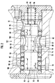
- Fig. 1 shows in axial section as Example a spray device 2 for Coating liquid.
- a nozzle head 10 of the Spray device 2 contains a separating ring 12 and a nozzle element 14, which has a fluid channel 20 for Shaping air 30 and a fluid channel 22 for Atomizing air 32 separates from each other.
- projections or horns 34 of an air distributor 16 form that End of the shaping air fluid channel 20 and direct the Forming air 30 on the atomized Coating material jet 36 to get it from a round to shape into a flat cross-sectional shape.
- High voltage electrodes 38 for electrostatic The coating material can be charged in or next to the air flow of the shaping air 30 or be arranged in a suitable other place.
- a Union nut 18 holds the elements on one Housing 40 of the spray device 2.
- the coating material is replaced by a Fluid channel 24 of a central spray opening 42 on Nozzle element 14 supplied and sprayed there when through a valve needle 44 from a valve seat 46 an actuator 48 against the Spring force of a biasing spring 50 is lifted off.
- This spray nozzle valve 44, 46 is by the Bias spring 50 closed and can counter be opened by their spring force Actuating compressed air if this Actuating air from the control unit 9 via a Actuating air fluid channel 26 into a pressure chamber 51 is passed and there a piston 52 of the Actuator 48 against Preload spring 50 moves to the right.
- the Valve needle 44 and the piston 52 are replaced by a further spring 54 axially held together so that they are moved axially together. at closed spray nozzle valve 44, 46 can do that Coating material through a fluid channel 28 be recirculated.
- a sensor 62 is attached to the adapter 8, which with one attached to the piston 52 Sensor pin 56 mechanical, inductive, capacitive or interacts optically and thereby the Axial positions of the valve needle 44, and thus also the open or closed position of the Spray nozzle valve 44, 46 recognizes and over a Telecommunication route 64, e.g. electrical or optical conductors or a wireless transmission path reports the control unit 9.
- a Telecommunication route 64 e.g. electrical or optical conductors or a wireless transmission path reports the control unit 9.
- the objects to be coated are usually from a transport device automatically on the spray device 2 past.
- the supply of the Coating material switched off so that Coating material does not pass the objects is injected into the environment. This means that Coating device during a working day switched on and off very often. If the individual fluid channels 20, 22, 24, 26 and 28 switched on for this purpose in the control unit 9 and switched off, you have a very long time Fluid channel paths through which Response delays arise.
- the valve device 70 is close to this disadvantage arranged on or in the spray device 2, preferably in the adapter 8.
- Die Valve device 70 also has the large one Advantage that they have the spray nozzle valve 44, 46th only opens if already Atomizing air 32 and shaping air 30 from the Spray device 2 emerge, or vice versa First, the spray nozzle valve 44, 46 closes before the atomizing air and the shaping air off. This will surely turn everything into Spray nozzle valve 44, 46 exiting Coating material sprayed properly and it cannot drop in the direction of that object to be coated or as a drop fall off.
- the valve device 70 has the other Advantage that the compressed air it controls, which actuates the spray nozzle valve 44, 46, too the valve device 70 is actuated without this an expensive electromagnetic multi-valve arrangement or an expensive computer control in the Control device 9 is required.
- the valve device 70.1 is shown in FIG Closed position and in Fig. 3 in the open position shown, between which a valve slide 74 in a slide guide channel 76 of a valve housing 72 by a distance "x" in Slider longitudinal direction is axially displaceable.
- the Slider 74 is against the wall of the guide channel 76 by sealing means, e.g. O-rings 69 sealed.
- a section of the actuation air duct 26 leads through one in the guide channel 76 formed control pressure chamber 88, in which the pressure the actuating air for the spray nozzle valve 44, 46 the slide 74 against the force of a compression spring 86 from the closed position in FIG. 2 to the open position 3 can move axially.
- the pressure of the actuating air drops Slider 74 by the spring 86 from the open position in Fig. 3 moved back to the closed position of Fig. 2.
- the control pressure chamber 88 is between one Slider face 90 and an inner housing face 92 at one end of slide 74 educated.
- the compression spring 86 is at the other Slide end opposite between one directed slide face 91 and one of her opposite inner housing end face 93 clamped.
- the axial movements of the slide 74 are limited by stops 94 and 95.
- the guide channel 76 has in the housing 72 in the area of the control pressure chamber 88 a fluid inlet 78 and a fluid outlet 82 of the actuation air channel 26.
- the fluid inlet 78 is in any axial position of the slide 74 open to the control pressure chamber 88 and could therefore instead be shown in the Sidewall also in the housing end face 92 be formed, which in all axial positions the slide 74 of the slide face 90 with opposite axial distance and the control pressure chamber 88 limited. Because of this distance ensured that the actuating compressed air through their fluid inlet 78 at all axial Slider positions in the control pressure chamber 88 can reach.
- the fluid outlet 82 of the Actuating air duct 26 has a larger axial Distance as the fluid inlet 78 from the Control pressure space 88 delimiting slide face 90 arranged, based on that in FIG Shown closed position of the slide 74th
- spray devices 2 without atomizing air and with or without Forming air work, or with air, which over Outer surfaces of the spray device 2 flow around them to keep clean.
- the fluid inlet 80 and Fluid outlet 84 of the atomizing air channel have one smaller axial distance "y" from each other than that Fluid outlet 82 from the fluid inlet 78 of the Actuating air duct 26.
- the one in slide 74 formed connecting portion 98 has a Fluid outlet 84 of the atomizing air channel 22 axially closer end 102 and one axially towards towards the piston end face 90 of the control pressure chamber axially further distal end 104. These two Ends 102 and 104 are axially far apart, that the connecting portion 98 at all axial Positions of slide 74 with fluid inlet 80 of the atomizer air duct 22 in terms of flow connected is.
- the fluid outlet 84 as the fluid inlet, and the Fluid inlet 80 as a fluid outlet further Serve fluid channel 22, i.e. their line connections of the fluid channel 22 can be interchanged.
- the connecting portion 98 is preferred 2 and 3 one in the slide 74th formed annular groove, the axial length between their end faces 102 and 104 is at least as large like the short distance "y" plus the axial Width of fluid inlet 80 and / or Fluid outlet 84 of the associated fluid channel 22.
- a bypass 106 is a narrow throttle channel formed and connects the fluid outlet 82 of the Actuating air duct 26 bypassing the Slider 74 in all axial slide positions with the control pressure chamber 88. This can this fluid outlet 82 is the pressure of the actuating air Dismantle into the control pressure chamber 88 if this fluid outlet 82 of the actuating air channel 26 is closed by the slide 64 when this from the open position of Fig. 3 in the 2 is moved axially.
- FIGS. 1 and 2 show a further embodiment 70.2 of the Valve device.
- it corresponds to Embodiment according to FIGS. 1 and 2, which is why Identical parts with the same reference numbers are.
- the main difference is that in addition to the actuating air duct 26 not just one more, but two more fluid channels passed through them in the present Example of atomizer air duct 22 and Forming air duct 20.
- the axial movement path of the Slider 74 for connecting and disconnecting the Fluid inlet 80 and the fluid outlet 84 of the Atomizer air duct 22 is labeled "y1"
- the axial movement path of the slide 74 for Connect or disconnect the fluid inlet 79 from the Fluid outlet 83 of the shaping air duct 20 is with designated "y2".
- the axial lengths of the two Movement paths "y1" and “y2" can be the same or be different and are each much shorter than the axial travel "x" of the slider 74. for connecting or disconnecting the fluid inlet 78 and the actuating air duct fluid outlet 82 26 with each other or from each other.
- the one in slide 74 formed connecting section of the The shaping air duct 20 is 101 in FIG. 4 designated.
- the fluid inlet 80 can Fluid outlet 84 of the atomizer air channel 22 diametrically opposite to the guide channel 76, and fluid inlet 79 may be fluid outlet 83 diametrically opposite.
- one Valve device 70.3 according to FIGS. 5 and 6 two valve devices according to FIGS. 2 and 3 arranged in parallel next to each other, one for the Atomizer air duct 22 and one for the Forming air duct 20 of Fig. 4.
- Your Control pressure spaces 88 are fluid connected in parallel, the fluid inlets 78 on upstream branch of the actuation air duct 26 are interconnected, and the fluid outlets 82 on the downstream branch of the Actuating air duct 26 connected to each other are.
- Double valve device shown in the open position 70.4 are two slides 74 opposite to each other in a common Guide channel 76 arranged such that they have a have common control pressure chamber 88, the axial on both sides of a slide face 90 one of the two sliders 74 is axially limited.
- the compression springs 86 are on the opposite outer protruding End faces 91 of the slider 74 arranged.
- the Control pressure chamber 88 has only one Fluid inlet 78 on the upstream side of the Actuating air duct 26, but two fluid outlets 82 on the downstream side of the Actuating air duct 26, each one is assigned to another of the two slides 74.
- in the is the axial region of the right control spool 74 a fluid inlet 80 and a fluid outlet 84 of the Atomizer air duct 22 formed in the housing 72, between which of these sliders 74 and the housing 72 form a valve 120, which is from the right Slider 74 is opened before the Passage between fluid inlet 78 and fluid outlet 82 of the actuating air channel 26 opens when it is from the closed position shown in Fig. 7 to the right moved to the open position shown in Fig. 8 becomes.
- valve devices 70.1, 70.2, 70.3 and 70.4 can not only for spray devices, but also for other facilities and purposes other than the described are used.
Description
Die Erfindung betrifft eine Sprühbeschichtungseinrichtung gemäß dem Oberbegriff von Anspruch 1. Eine derartige Sprühbeschichtungseinrichtung ist aus US 3 841 555 bekannt. The invention relates to a Spray coating device according to the preamble of claim 1. Such a spray coating device is known from US 3,841,555.
Aus der DE 22 09 896 C2 ist eine Sprühbeschichtungsvorrichtung bekannt, mit welcher flüssiges Beschichtungsmaterial auf einen zu beschichtenden Gegenstand gesprüht werden kann. Das Beschichtungsmaterial strömt über ein Ventil, dessen Ventilkörper eine nadelartige Form hat, zu einer Sprühdüse, an welcher der Zerstäubervorgang durch Druckluft, sogenannte Zerstäuberluft, unterstützt wird. Der Sprühstrahl hat eine runde Querschnittsform.From DE 22 09 896 C2 is one Spray coating device known with which liquid coating material towards you coating object can be sprayed. The Coating material flows through a valve, whose valve body has a needle-like shape a spray nozzle on which the atomizing process through compressed air, so-called atomizing air, is supported. The spray jet has a round one Cross-sectional shape.
Der nadelförmige Ventilkörper kann zum Einschalten des Beschichtungsmaterialstromes durch einen Abzugsbügel von Hand betätigt werden, wenn die Sprühvorrichtung eine Hand-Sprühpistole ist, oder durch Druckluft entgegen der Kraft einer Feder betätigt werden, wenn es sich um eine automatische Sprühvorrichtung handelt.The needle-shaped valve body can be switched on the coating material flow through a Trigger guard operated by hand when the Spray device is a hand-held spray gun, or by compressed air against the force of a spring be operated if it is an automatic Spray device is.
Ferner ist es bekannt, auf den Sprühstrahl von zwei gegenüberliegenden Seiten her Druckluft aufzubringen, sogenannte Formungsluft, um den runden Sprühstrahl in einen flachen Sprühstrahl umzuformen. Außerdem ist es bekannt, Beschichtungsmaterial vor oder nach der Sprühdüse durch Elektroden mit Hochspannung elektrostatisch aufzuladen und Druckluft über die Elektroden zu führen, damit kein Beschichtungsmaterial an ihnen haften kann. Desweiteren ist es bekannt, einen schwachen Druckluftstrom über das vordere Ende der Sprühvorrichtung strömen zu lassen, damit sich an ihn keine zerstäubten Beschichtungsmaterialpartikel ansammeln können. Die Druckluft zur Betätigung des genannten Ventils wird im folgenden Betätigungsluft genannt. Die anderen Druckluftströme, sofern kein bestimmter von ihnen angesprochen wird, werden im folgenden jeweils als "Betriebsluft" oder "Betriebsluftstrom" bezeichnet. Beim gleichzeitigen Einschalten der Betätigungsluft und der Betriebsluftströme besteht die Gefahr, daß Beschichtungsmaterial unkontrolliert versprüht wird, bevor die Betriebsluft wirksam werden kann. Wenn die Betätigungsluft und die Betriebsluftströme gleichzeitig abgeschaltet werden, besteht in entsprechender Weise wiederum die Gefahr, daß der Beschichtungsmaterial-Sprühstrahl nicht mehr ausreichend kontrolliert wird und dadurch Beschichtungsfehler entstehen, oder daß nach dem Abschalten noch Beschichtungsmaterial aus der Sprühvorrichtung tropft. Zur Vermeidung dieser Nachteile sind im Stand der Technik teuere elektromagnetische Mehrventil-Anordnungen und Steuerschaltungen bekannt, durch welche beim Einschalten des Beschichtungsvorganges sichergestellt wird, daß das Ventil für das Beschichtungsmaterial erst dann öffnet, wenn mindestens einer der Betriebsluftströme bereits zuvor eingeschaltet wurde, und daß dieser mindestens eine Betriebsluftstrom erst dann abgeschaltet wird, wenn zuvor der Beschichtungsmaterialstrom abgeschaltet wurde. It is also known to spray on two opposite sides forth compressed air apply, so-called shaping air, around the round spray into a flat spray reshape. It is also known Coating material before or after the spray nozzle by electrostatic electrodes with high voltage charge and compressed air through the electrodes too so no coating material on them can adhere. Furthermore, it is known to be a weak stream of compressed air over the front end of the Spray device to let it flow no atomized coating material particles can accumulate. The compressed air for actuating the mentioned valve is actuating air in the following called. The other compressed air flows, if none certain of them are addressed in the following each as "operating air" or "Operating airflow" referred to. At the same time Switch on the actuating air and the Operating air flows there is a risk that Sprayed coating material in an uncontrolled manner before the operating air can take effect. If the actuating air and the operating air flows switched off at the same time consists in accordingly again the danger that the Coating material spray no longer is adequately controlled and thereby Coating errors arise, or that after Turn off coating material from the Sprayer drips. To avoid this Disadvantages are more expensive in the prior art electromagnetic multi-valve arrangements and Control circuits known by which Switch on the coating process it is ensured that the valve for the Coating material only opens when at least one of the operating air flows already was previously turned on, and that this only then at least one operating air flow is switched off if the Coating material stream was switched off.
Anstelle durch Sprühdüsen kann der Beschichtungsmaterialstrom-auch durch ein Rotationszerstäuberelement oder eine andere Technik versprüht werden.Instead of using spray nozzles, the Coating material flow-also through one Rotary atomizer element or other technique be sprayed.
Die Betriebsluftströme können nur dann einzeln geregelt werden, wenn sie der Sprühvorrichtung in getrennten Leitungen zugeführt werden. Da das Steuergerät, welches die Betriebsluftströme und die Betätigungsluft steuert, über verhältnismäßig lange Leitungen und großem Abstand von der Sprühvorrichtung angeordnet ist, beispielsweise in einem elektrischen Schaltschrank oder im Steuerteil eines Roboters, entstehen lange Verzögerungszeiten bis die betreffende Luft vom Steuergerät zur Sprühvorrichtung gelangt.The operating air flows can then only individually to be regulated when in the sprayer separate lines are supplied. Since that Control unit, which the operating air flows and the Actuating air controls over a relatively long time Lines and large distance from the Spray device is arranged, for example in an electrical control cabinet or in the control section of a robot, there are long delay times until the air in question from the control unit to Spray device arrives.
Eine Sprühvorrichtung wird nicht nur am Beginn und Ende eines Arbeitstages, sondern während eines Arbeitstages viele hundert mal eingeschaltet und ausgeschaltet, weil der Beschichtungsvorgang zwischen den verschiedenen zu beschichtenden Gegenständen immer ausgeschaltet und dann erneut eingeschaltet werden muß. Die Gegenstände werden normalerweise von automatischen Transportanlagen an einer Sprühstation vorbeigeführt, wo sich die eine oder mehrere Sprühvorrichtungen befinden.A spray device is not just at the beginning and End of a working day but during a Working day turned on hundreds of times and turned off because of the coating process between the different ones to be coated Objects always switched off and then again must be switched on. The objects are usually from automatic transportation systems passed a spray station where one or several spray devices.
Wenn ein Druckluftstrom erst in der Sprühvorrichtung auf Betriebsluftströme aufgeteilt wird, beispielsweise auf einen Zerstäuberluftstrom und einen Formungsluftstrom, dann kann zwar an der Sprühvorrichtung durch Stellschrauben die Strömungsmenge der Zerstäuberluft und der Formungsluft eingestellt werden, ihre Drücke sind jedoch nicht unabhängig voneinander einstellbar.If a stream of compressed air is only in the Spray device divided into operating air flows is, for example, to an atomizing air flow and a shaping air flow, then at the Spray device by adjusting the Flow rate of the atomizing air and the Forming air can be adjusted, their pressures are but not adjustable independently.
Durch die Erfindung soll die Aufgabe gelöst werden, eine Möglichkeit zu schaffen, durch welche ein Spritzen von Beschichtungsmaterial-Klumpen auf das zu beschichtende Objekt beim Einschalten und ein Nachtropfen von Beschichtungsmaterial an der Sprühvorrichtung bei ihrem Ausschalten vermieden werden; durch welche die verschiedenen Luftströme und das Einschalten und Ausschalten des Beschichtungsmaterials getrennt voneinander gesteuert oder geregelt werden können, ohne daß umfangreiche, teuere Steuereinrichtungen oder Multiventilanordnungen erforderlich sind; und durch welche Reaktionsverzögerungen als Folge von langen Fluidleitungen beim Einschalten und Ausschalten vermieden werden.The object of the invention is to be achieved to create a way through which a Spraying lumps of coating material onto the object to be coated when switched on and on Dripping of coating material on the Avoid spray device when turned off become; through which the different air flows and turning on and off the Coating material separately can be controlled or regulated without extensive, expensive control devices or Multi-valve arrangements are required; and through what response delays as a result of long Fluid lines when switching on and off be avoided.
Diese Aufgabe wird gemäß der Erfindung durch die Merkmale von Anspruch 1 gelöst.This object is achieved according to the invention by Features of claim 1 solved.
Weitere Merkmale der Erfindung sind in den Unteransprüchen enthalten.Further features of the invention are in the Subclaims included.
Da anstelle von Luftströmen auch andere Materialströme verwendet werden können, werden sie im folgenden insgesamt als "Fluidströme" bezeichnet. Durch die Erfindung werden alle Fluidströme durch den Druck eines dieser Fluidströme in der neuen Ventileinrichtung gesteuert, ohne daß elektromagnetische oder elektropneumatische Mehrventil-Einrichtungen oder aufwendige Steuerschaltungen erforderlich sind. Die Ventileinrichtung kann gemäß der Erfindung direkt an der Sprühvorrichtung angeordnet werden, so daß die von ihr gesteuerten Fluidströme ohne Zeitverzögerung an der Sprühvorrichtung wirksam werden können. Alle Fluidströme können der Sprühvorrichtung einzeln zugeführt werden.There are others instead of air flows Material flows can be used, they will hereinafter referred to as "fluid flows" designated. Through the invention, everyone Fluid flows through the pressure of one of these Fluid flows in the new valve device controlled without electromagnetic or electropneumatic multi-valve devices or complex control circuits are required. The Valve device can directly according to the invention be arranged on the spray device so that the fluid flows it controls without Time delay on the sprayer effective can be. All fluid flows can Spray device can be fed individually.
Die Erfindung wird im folgenden mit Bezug auf die Zeichnungen anhand von bevorzugten Ausführungsformen als Beispiele beschrieben. In den Zeichnungen zeigen
- Fig. 1
- eine Sprühbeschichtungseinrichtung nach der Erfindung, teilweise geschnitten;
- Fig. 2
- einen vergrößerten Längsschnitt durch eine erste Ausführungsform einer Ventileinrichtung nach der Erfindung in ihrer Schließstellung;
- Fig. 3
- die Ventilanordnung von Fig. 2 in Offenstellung;
- Fig. 4
- schematisch einen Axialschnitt durch eine zweite Ausführungsform einer Ventileinrichtung nach der Erfindung in Schließstellung;
- Fig. 5
- schematisch eine Stirnansicht einer dritten Ausführungsform einer Ventileinrichtung gemäß der Erfindung;
- Fig. 6
- schematisch eine Draufsicht auf die Ventilanordnung von Fig. 5,
- Fig. 7
- einen vergrößerten Axialschnitt einer dritten Ausführungsform einer Ventilanordnung nach der Erfindung in Schließstellung,
- Fig. 8
- die Ventilanordnung von Fig. 7 in Offenstellung.
- Fig. 1
- a spray coating device according to the invention, partially cut;
- Fig. 2
- an enlarged longitudinal section through a first embodiment of a valve device according to the invention in its closed position;
- Fig. 3
- the valve assembly of Figure 2 in the open position.
- Fig. 4
- schematically shows an axial section through a second embodiment of a valve device according to the invention in the closed position;
- Fig. 5
- schematically an end view of a third embodiment of a valve device according to the invention;
- Fig. 6
- schematically a top view of the valve arrangement of FIG. 5,
- Fig. 7
- 2 shows an enlarged axial section of a third embodiment of a valve arrangement according to the invention in the closed position,
- Fig. 8
- 7 in the open position.
In Fig. 1 ist eine Sprühbeschichtungseinrichtung
mit einer Sprühvorrichtung 2 dargestellt, welche
auf einem Träger 4 durch einen Dreh-Spannverschluß
6 montiert ist. Mit einem Adapter 8 kann die
Sprühvorrichtung 2 an einem Roboter, Hubständer,
Handgriff oder anderen Träger (nicht dargestellt)
angebaut werden. Die Sprühvorrichtung wird von
einem Steuergerät 9 gesteuert, welches an einer von
ihr entfernten Stelle angeordnet ist,
beispielsweise im Steuerteil eines Roboters oder in
einem Schaltschrank. In Fig. 1 is a spray coating device
shown with a spray device 2, which
on a carrier 4 by means of a
Die Sprühvorrichtung kann zum Sprühen von flüssigem
oder pulverförmigem Beschichtungsmaterial
ausgebildet sein. Fig. 1 zeigt im Axialschnitt als
Beispiel eine Sprühvorrichtung 2 für
Beschichtungsflüssigkeit. Ein Düsenkopf 10 der
Sprühvorrichtung 2 enthält einen Trennring 12 und
ein Düsenelement 14, welche einen Fluidkanal 20 für
Formungsluft 30 und einen Fluidkanal 22 für
Zerstäuberluft 32 voneinander trennt. Vorsprünge
oder Hörner 34 eines Luftverteilers 16 bilden das
Ende des Formungsluft-Fluidkanals 20 und lenken die
Formungsluft 30 auf den zerstäubten
Beschichtungsmaterialstrahl 36, um ihn von einer
runden in eine flache Querschnittsform umzuformen.
Hochspannungselektroden 38 zur elektrostatischen
Aufladung des Beschichtungsmaterials können in oder
neben dem Luftstrom der Formungsluft 30 oder an
geeigneter anderer Stelle angeordnet sein. Eine
Überwurfmutter 18 hält die Elemente an einem
Gehäuse 40 der Sprühvorrichtung 2.The spray device can be used to spray liquid
or powder coating material
be trained. Fig. 1 shows in axial section as
Example a spray device 2 for
Coating liquid. A
Das Beschichtungsmaterial wird durch einen
Fluidkanal 24 einer zentralen Sprühöffnung 42 am
Düsenelement 14 zugeführt und dort versprüht, wenn
eine Ventilnadel 44 von einem Ventilsitz 46 durch
eine Betätigungseinrichtung 48 entgegen der
Federkraft einer Vorspannfeder 50 abgehoben wird.
Dieses Sprühdüsenventil 44, 46 wird durch die
Vorspannfeder 50 geschlossen und kann entgegen
ihrer Federkraft geöffnet werden durch
Betätigungsdruckluft, wenn diese
Betätigungsluft von dem Steuergerät 9 über einen
Betätigungsluft-Fluidkanal 26 in eine Druckkammer
51 geleitet wird und dort einen Kolben 52 der
Betätigungseinrichtung 48 entgegen der
Vorspannfeder 50 nach rechts verschiebt. Die
Ventilnadel 44 und der Kolben 52 werden durch eine
weitere Feder 54 axial zusammengehalten, so daß sie
jeweils zusammen axial bewegt werden. Bei
geschlossenem Sprühdüsenventil 44, 46 kann das
Beschichtungsmaterial durch einen Fluidkanal 28
rezirkuliert werden.The coating material is replaced by a
Auf dem Adapter 8 ist ein Sensor 62 befestigt,
welcher mit einem an dem Kolben 52 befestigten
Sensorstift 56 mechanisch, induktiv, kapazitiv oder
optisch zusammenwirkt und dadurch die
Axialpositionen der Ventilnadel 44, und damit auch
die Offenstellung oder Schließstellung des
Sprühdüsenventils 44, 46 erkennt und über einen
Fernübertragungsweg 64, z.B. elektrische oder
optische Leiter oder ein drahtloser Übertragungsweg
dem Steuergerät 9 meldet.A
Die zu beschichtenden Objekte (nicht dargestellt)
werden normalerweise von einer Transportvorrichtung
automatisch an der Sprühvorrichtung 2
vorbeigeführt. Beim Wechsel von einem Objekt zu
einem anderen Objekt wird die Zufuhr des
Beschichtungsmaterials abgeschaltet, damit das
Beschichtungsmaterial nicht an den Objekten vorbei
in die Umgebung gespritzt wird. Dadurch muß die
Beschichtungsvorrichtung während eines Arbeitstages
sehr häufig eingeschaltet und ausgeschaltet werden.
Wenn die einzelnen Fluidkanäle 20, 22, 24, 26 und
28 hierfür in dem Steuergerät 9 eingeschaltet und
ausgeschaltet werden, hat man sehr lange
Fluidkanal-Wege, durch welche
Reaktionsverzögerungen entstehen. Zur Vermeidung
dieses Nachteiles ist die Ventileinrichtung 70 nahe
an oder in der Sprühvorrichtung 2 angeordnet,
vorzugsweise in dem Adapter 8. Die
Ventileinrichtung 70 hat außerdem den großen
Vorteil, daß sie das Sprühdüsenventil 44, 46
jeweils erst dann öffnet, wenn bereits
Zerstäuberluft 32 und Formungsluft 30 aus der
Sprühvorrichtung 2 austreten, bzw. umgekehrt sie
zuerst das Sprühdüsenventil 44, 46 schließt, bevor
sie die Zerstäuberluft und die Formungsluft
abschaltet. Damit wird mit Sicherheit alles aus dem
Sprühdüsenventil 44, 46 austretende
Beschichtungsmaterial ordnungsgemäß zerstäubt und
es kann nicht in Tropfenform auf das zu
beschichtende Objekt gelangen oder als Tropfen
abfallen. Die Ventileinrichtung 70 hat den weiteren
Vorteil, daß die von ihr gesteuerte Druckluft,
welche das Sprühdüsenventil 44, 46 betätigt, auch
die Ventileinrichtung 70 betätigt, ohne daß hierfür
eine teuere elektromagnetische Mehr-Ventil-Anordnung
oder eine teuere Computersteuerung im
Steuergerät 9 erforderlich ist. Mehrere
Ausführungsformen der Ventileinrichtung 70 werden
im folgenden mit Bezug auf die Fig. 2 bis 8
beschrieben, in welchen die Ventileinrichtung 70
den verschiedenen Varianten entsprechend mit 70.1,
70.2, 70.3 und 70.4 durchnumeriert ist.The objects to be coated (not shown)
are usually from a transport device
automatically on the spray device 2
past. When changing from an object to
Another object is the supply of the
Coating material switched off so that
Coating material does not pass the objects
is injected into the environment. This means that
Coating device during a working day
switched on and off very often.
If the individual
Die Ventileinrichtung 70.1 ist in Fig. 2 in
Schließstellung und in Fig. 3 in Offenstellung
dargestellt, zwischen welchen ein Ventil-Schieber
74 in einem Schieber-Führungskanal 76 eines Ventil-Gehäuses
72 um eine Strecke "x" in
Schieberlängsrichtung axial verschiebbar ist. Der
Schieber 74 ist gegen die Wand des Führungskanals
76 durch Dichtungsmittel, z.B. O-Ringe 69
abgedichtet. Ein Abschnitt des Betätigungsluftkanals
26 führt durch einen im Führungskanal 76
gebildeten Steuerdruckraum 88, in welchem der Druck
der Betätigungsluft für das Sprühdüsenventil 44, 46
den Schieber 74 entgegen der Kraft einer Druckfeder
86 von der Schließstellung in Fig. 2 in die Offenstellung
von Fig. 3 axial verschieben kann. Beim
Abfallen des Druckes der Betätigungsluft wird der
Schieber 74 von der Feder 86 von der Offenstellung
in Fig. 3 in die Schließstellung von Fig. 2 zurückbewegt.
Der Steuerdruckraum 88 ist zwischen einer
Schieberstirnfläche 90 und einer inneren Gehäusestirnfläche
92 am einen Ende des Schiebers 74
gebildet. Die Druckfeder 86 ist am anderen
Schieberende zwischen eine entgegengesetzt
gerichtete Schieberstirnfläche 91 und eine ihr
gegenüberliegende innere Gehäusestirnfläche 93
eingespannt. Die Axialbewegungen des Schiebers 74
werden durch Anschläge 94 und 95 begrenzt. The valve device 70.1 is shown in FIG
Closed position and in Fig. 3 in the open position
shown, between which a
Der Führungskanal 76 hat im Gehäuse 72 im Bereich
des Steuerdruckraums 88 einen Fluideinlaß 78 und
einen Fluidauslaß 82 des Betätigungsluftkanals 26.
Der Fluideinlaß 78 ist in jeder axialen Position
des Schiebers 74 zum Steuerdruckraum 88 hin offen
und könnte deshalb anstelle in der dargestellten
Seitenwand auch in der Gehäusestirnfläche 92
gebildet sein, welche bei allen axialen Positionen
des Schiebers 74 der Schieberstirnfläche 90 mit
axialem Abstand gegenüberliegt und den Steuerdruckraum
88 begrenzt. Durch diesen Abstand ist
sichergestellt, daß die Betätigungsdruckluft durch
ihren Fluideinlaß 78 bei allen axialen
Schieberpositionen in den Steuerdruckraum 88
gelangen kann. Der Fluidauslaß 82 des
Betätigungsluftkanals 26 ist mit größerem axialem
Abstand als der Fluideinlaß 78 von der den
Steuerdruckraum 88 begrenzenden Schieberstirnfläche
90 angeordnet, bezogen auf die in Fig. 2
dargestellte Schließstellung des Schiebers 74.The
Mit größerem axialem Abstand von der den
Steuerdruckraum 88 begrenzenden Schieberstirnfläche
90 als der Betätigungsluft-Fluidauslaß 82 ist der
Führungskanal 76 mit mindestens einem weiteren
Fluideinlaß 80 und mindestens einem weiteren
Fluidauslaß 84 versehen, welche in der in Fig. 2
gezeigten Schließstellung voneinander getrennt und
in der in Fig. 3 gezeigten Offenstellung
miteinander verbunden sind und einen durch die
Ventileinrichtung 70.1 hindurchführenden weiteren
Abschnitt für eines der anderen Fluide bilden. Zur
Beschreibung des Ausführungsbeispieles wird
angenommen, daß dieses weitere Fluid Zerstäuberluft
des Zerstäuberluftkanals 22 ist. Statt dessen
könnte es auch der Formungsluftkanal 20 oder ein
anderer Luftkanal zur Zufuhr von Luft zur
Sprühvorrichtung 2 sein. Es gibt Sprühvorrichtungen
2, die ohne Zerstäuberluft und mit oder ohne
Formungsluft arbeiten, oder mit Luft, welche über
Außenflächen der Sprühvorrichtung 2 strömt, um sie
sauber zu halten. Der Fluideinlaß 80 und
Fluidauslaß 84 des Zerstäuberluftkanals haben einen
kleineren axialen Abstand "y" voneinander als der
Fluidauslaß 82 vom Fluideinlaß 78 des
Betätigungsluftkanals 26. Zwischen den Einlässen 78
und 80 einerseits und ihren Auslässen 82 und 84
andererseits befindet sich je eines der
Dichtungsmittel 69, damit sie bei der in Fig. 2
gezeigten-Schließstellung voneinander getrennt
sind. Durch die unterschiedlichen axialen Abstände
"x" und "y" wird erreicht, daß bei Bewegung des
Schiebers 74 von der Schließstellung von Fig. 2 in
die Offenstellung von Fig. 3 zuerst der Fluideinlaß
80 mit dem Fluidauslaß 84 des Zerstäsuberluftkanals
22 nach der kurzen Wegstrecke "y" über einen im
Schieber 74 gebildeten Verbindungsabschnitt 98
miteinander strömungsmäßig verbunden werden, bevor
der Fluideinlaß 78 mit dem Fluidauslaß 82 des
Betätigungsluftkanals 26 nach der längeren
Wegstrecke "x" miteinander verbunden werden. With a larger axial distance from the
Umgekehrt wird erreicht, wenn der Schieber 74 von
der Offenstellung von Fig. 3 in die Schließstellung
von Fig. 2 bewegt wird, daß er an seiner den
Steuerdruckraum 88 begrenzenden Schieberstirnfläche
90 zuerst den Fluidauslaß 82 vom Fluideinlaß 78 des
Betätigungsluftkanals 26 trennt, bevor der
Steuerschieber 74 den Fluidauslaß 84 vom
Fluideinlaß 80 des Zerstäuberluftkanals 22 trennt.
Damit ist sichergestellt, daß vor, während und nach
der Abgabe von Beschichtungsmaterial an der
Sprühöffnung 42 der Sprühvorrichtung 2 auch das
weitere Fluid, im vorliegenden Falle Zerstäuberluft
des Zerstäuberluftkanals 22 vorhanden ist und für
eine ordnungsgemäße Zerstäubung des
Beschichtungsmaterials sorgt. Der im Schieber 74
gebildete Verbindungsabschnitt 98 hat ein dem
Fluidauslaß 84 des Zerstäuberluftkanals 22 axial
näher gelegenes Ende 102 und ein axial in Richtung
zur Kolbenstirnfläche 90 der Steuerdruckkammer hin
axial weiter entferntes Ende 104. Diese beiden
Enden 102 und 104 liegen axial soweit auseinander,
daß der Verbindungsabschnitt 98 bei allen axialen
Positionen des Schiebers 74 mit dem Fluideinlaß 80
des Zerstäuberluftkanals 22 strömungsmäßig
verbunden ist. Gemäß einer anderen Anwendung kann
der Fluidauslaß 84 als Fluideinlaß, und der
Fluideinlaß 80 als Fluidauslaß des weiteren
Fluidkanals 22 dienen, d.h. ihre Leitungsanschlüsse
des Fluidkanals 22 können vertauscht werden. Conversely, when the
Der Verbindungsabschnitt 98 ist vorzugsweise
entsprechend den Fig. 2 und 3 eine im Schieber 74
gebildete Ringnut, deren axiale Länge zwischen
ihren Endflächen 102 und 104 mindestens so groß ist
wie die kurze Wegstrecke "y" plus der axialen
Breite des Fluideinlasses 80 und/oder des
Fluidauslasses 84 des zugehörigen Fluidkanals 22.The connecting
Ein Bypass 106 ist als enger Drosselkanal
ausgebildet und verbindet den Fluidauslaß 82 des
Betätigungsluftkanals 26 unter Umgehung des
Schiebers 74 in allen axialen Schieberpositionen
mit dem Steuerdruckraum 88. Dadurch kann sich an
diesem Fluidauslaß 82 der Druck der Betätigungsluft
in die Steuerdruckkammer 88 hinein abbauen, wenn
dieser Fluidauslaß 82 des Betätigungsluftkanals 26
durch den Schieber 64 verschlossen wird, wenn
dieser von der Offenstellung von Fig. 3 in die
Schließstellung von Fig. 2 axial bewegt wird.A
Fig. 4 zeigt eine weitere Ausführungsform 70.2 der
Ventileinrichtung. Sie entspricht im Prinzip der
Ausführungsform nach den Fig. 1 und 2, weshalb
gleiche Teile mit gleichen Bezugszahlen versehen
sind. Ihr wesentlicher Unterschied besteht darin,
daß zusätzlich zum Betätigungsluftkanal 26 nicht
nur ein weiterer, sondern zwei weitere Fluidkanäle
durch sie hindurchgeführt sind, im vorliegenden
Beispiel der Zerstäuberluftkanal 22 und der
Formungsluftkanal 20. Der axiale Bewegungsweg des
Schiebers 74 für das Verbinden und Trennen des
Fluideinlasses 80 und des Fluidauslasses 84 des
Zerstäuberluftkanals 22 ist mit "y1" bezeichnet,
und der axiale Bewegungsweg des Schiebers 74 zum
Verbinden oder Trennen des Fluideinlasses 79 vom
Fluidauslaß 83 des Formungsluftkanals 20 ist mit
"y2" bezeichnet. Die axialen Längen der beiden
Bewegungswege "y1" und "y2" können gleich oder
unterschiedlich sein und sind je wesentlich kürzer
als der axiale Bewegungsweg "x" des Schiebers 74 .
zum Verbinden oder Trennen des Fluideinlasses 78
und des Fluidauslasses 82 des Betätigungsluftkanals
26 miteinander bzw. voneinander. Der im Schieber 74
gebildete Verbindungsabschnitt des
Formungsluftkanals 20 ist in Fig. 4 mit 101
bezeichnet.4 shows a further embodiment 70.2 of the
Valve device. In principle, it corresponds to
Embodiment according to FIGS. 1 and 2, which is why
Identical parts with the same reference numbers
are. The main difference is
that in addition to the actuating
Wie Fig. 4 zeigt, kann der Fluideinlaß 80 dem
Fluidauslaß 84 des Zerstäuberluftkanals 22
diametral zum Führungskanal 76 gegenüberliegen, und
der Fluideinlaß 79 kann dem Fluidauslaß 83
diametral gegenüberliegen.As shown in FIG. 4, the
Bei der dritten Ausführungsform einer
Ventileinrichtung 70.3 nach den Fig. 5 und 6 sind
zwei Ventileinrichtungen nach den Fig. 2 und 3
parallel nebeneinander angeordnet, eine für den
Zerstäuberluftkanal 22 und eine für den
Formungsluftkanal 20 von Fig. 4. Ihre
Steuerdruckräume 88 sind strömungsmäßig
parallel geschaltet, wobei die Fluideinlässe 78 am
stromaufwärtigen Zweig des Betätigungsluftkanals 26
miteinander verbunden sind, und die Fluidauslässe
82 am stromabwärtigen Zweig des
Betätigungsluftkanals 26 miteinander verbunden
sind.In the third embodiment, one
Valve device 70.3 according to FIGS. 5 and 6
two valve devices according to FIGS. 2 and 3
arranged in parallel next to each other, one for the
Bei der in Fig. 7 in Schließstellung und in Fig. 8
in Offenstellung dargestellten Doppel-Ventileinrichtung
70.4 sind zwei Schieber 74
entgegengesetzt zueinander in einem gemeinsamen
Führungskanal 76 angeordnet, derart, daß sie einen
gemeinsamen Steuerdruckraum 88 haben, der axial
beidseitig je von einer Schieberstirnfläche 90
eines der beiden Schieber 74 axial begrenzt wird.
Der kleinste axiale Abstand der
Schieberstirnflächen 90 voneinander wird durch ihre
Anschläge 94 definiert, welche bei der in Fig. 7
dargestellten Schließstellung axial aneinander
anliegen. Die Druckfedern 86 sind an den
entgegengesetzt zueinander wegragenden äußeren
Stirnflächen 91 der Schieber 74 angeordnet. Der
Steuerdruckraum 88 hat nur einen einzigen
Fluideinlaß 78 auf der stromaufwärtigen Seite des
Betätigungsluftkanals 26, jedoch zwei Fluidauslässe
82 auf der stromabwärtigen Seite des
Betätigungsluftkanals 26, von welchen jeder einem
anderen der beiden Schieber 74 zugeordnet ist. Im
axialen Bereich des rechten Steuerschiebers 74 ist
ein Fluideinlaß 80 und ein Fluidauslaß 84 des
Zerstäuberluftkanals 22 im Gehäuse 72 gebildet,
zwischen welchen dieser Schieber 74 und das Gehäuse
72 ein Ventil 120 bilden, welches vom rechten
Schieber 74 jeweils geöffnet wird, bevor er den
Durchgang zwischen Fluideinlaß 78 und Fluidauslaß
82 des Betätigungsluftkanals 26 öffnet, wenn er von
der in Fig. 7 gezeigten Schließstellung nach rechts
in die in Fig. 8 gezeigte Offenstellung bewegt
wird. Umgekehrt wird die durch den Steuerdruckraum
88 führende Verbindung des Fluideinlasses 78 mit
dem Fluidauslaß 82 vom rechten Schieber 74
unterbrochen, bevor er das Ventil 120 schließt,
wenn er von der Offenstellung von Fig. 8 in die
Schließstellung von Fig. 7 nach links bewegt wird.
Entsprechend wie dieser rechts dargestellte
Schieber 74 arbeitet auch der in den Fig. 7 und 8
links dargestellte Schieber 74. Er verbindet den
Fluideinlaß 79 mit dem Fluidauslaß 83 des
Formungsluftkanals 20 strömungsmäßig, bevor er den
Fluideinlaß 78 mit dem Fluidauslaß 82 des
Betätigungsfluidkanals 26 verbindet, wenn er von
der Schließstellung von Fig. 7 in die Offenstellung
von Fig. 8 nach links bewegt wird. Ferner
unterbricht der links dargestellte Schieber 74
zuerst die Verbindung zwischen dem Fluideinlaß 78
und dem Fluidauslaß 82 des Betätigungsluftkanals
26, bevor er die Verbindung zwischen dem
Flüideinlaß 79 und dem Fluidauslaß 83 des
Formungsluftkanals 20 unterbricht, wenn er von der
Offenstellung von Fig. 8 in die Schließstellung von
Fig. 7 nach rechts bewegt wird, wenn der Druck der
Betätigungsluft im Steuerdruckraum 88 soweit
abfällt, daß die Druckfeder 86 stärker ist. Die
Druckfedern 86 der beiden Schieber 74 können derart
ausgebildet sein, daß beide Schieber 74 jeweils
gleichzeitig um gleiche oder unterschiedliche
axiale Strecken in Offenstellungs-Richtung oder in
Schließstellungs-Richtung bewegt werden.In the closed position in FIG. 7 and in FIG. 8
Double valve device shown in the open position
70.4 are two
Bei allen Ausführungsformen schaltet das
Steuergerät 9 bei Arbeitsbeginn die Druckluft
(Betätigungsluft, Formungsluft, Zerstäuberluft) von
allen Fluidkanälen, und vorzugsweise auch die
Zufuhr des Beschichtungsmaterials zum
Sprühdüsenventil 44, 46, gleichzeitig ein, und bei
Arbeitsende alle wieder gleichzeitig ab. Für das
temporäre Einschalten und Ausschalten nur des
Sprühbetriebes zwischen Arbeitsbeginn und
Arbeitsende wird vom Steuergerät 9 nur die
Betätigungsluft des Fluidkanals 26 eingeschaltet
und ausgeschaltet, während es alle anderen Fluide
eingeschaltet läßt.In all embodiments, this switches
Control unit 9 the compressed air at the start of work
(Actuating air, shaping air, atomizing air) from
all fluid channels, and preferably also the
Feeding the coating material to the
Die Ventileinrichtungen 70.1, 70.2, 70.3 und 70.4 können nicht nur für Sprüheinrichtungen, sondern auch für andere Einrichtungen und andere Zwecke als die beschriebenen verwendet werden.The valve devices 70.1, 70.2, 70.3 and 70.4 can not only for spray devices, but also for other facilities and purposes other than the described are used.
Claims (10)
- Spray coating device having a spray device and having at least two fluid channels which are connected to the spray device, wherein
at least two of the fluid channels (26, 22; 26, 22, 20) go through a valve device (70) which possesses a slide (74) in a guide channel (76) for opening and closing this fluid channel, characterised in that a section of a first fluid channel (26) of these fluid channels is a control pressure chamber (88) constructed in the guide channel (76) in which the pressure of a fluid of the first fluid channel (26) can move the slide (74) against the force of a springing means (86) from a closed position into an open position;
that the control pressure chamber (88) is bounded in the longitudinal direction of the slide by a fluid-controlled slide end face (90), on the one hand, and by an opposing surface (90, 92) separated from this slide (74), on the other hand;
that the control pressure chamber (88) in a housing (72) of the guide channel (76) has a fluid inlet (78) and a fluid outlet (82) of the first fluid channel (26) from which the fluid inlet (78) is open in each position of the slide (74) to the fluid-controlled slide end face (90), whereas the slide (74) in its closed position covers the fluid outlet (82) and in its open position opens the fluid outlet (82) into the control pressure chamber (88);
that in the closed position of the slide (74) the distance of the fluid-controlled slide end face (90) from the fluid outlet (82) of the first fluid channel (26) is greater than the distance of a connecting section (98) passing through the slide (74) of at least a second fluid channel (22, 20) of the fluid channels from a fluid inlet (80, 79) and/or fluid outlet (84, 83) of this second fluid channel (22, 20) in such a way that on moving the slide (74) from the closed position into the open position the second fluid channel (22, 20) is first of all opened before the first fluid channel (26) is then opened while on moving the slide (74) in the opposite direction from the open position into the closed position the first fluid channel (26) is first of all closed before the second fluid channel (22, 20) is then closed. - Spray coating device according to Claim 1, characterised in that the connecting section (98) has recesses formed at the perimeter of the slide (74) which are longer in the longitudinal direction of the slide than the fluid inlet (80, 79) and/or the fluid outlet (84, 83) of the second fluid channel (22, 20).
- Spray coating device according to one of the preceding claims, characterised in that the springing means (86) is arranged at the end of the slide (74) facing away from the slide end face (90) controlled by fluid pressure.
- Spray coating device according to one of the preceding claims, characterised in that in the slide (74) at least two connecting sections (98) are provided for connecting or isolating fluid inlets (80, 79) and fluid outlets (84, 83) of at least two of the second fluid channels (22, 20).
- Spray coating device according to one of the preceding claims, characterised in that the opposing surface is an end face (92) of the housing (72).
- Spray coating device according to one of Claims 1 to 4, characterised in that the opposing surface is a slide end face (90) controlled by fluid pressure of another slide (74) which is arranged in opposition to the first slide (74) and by this means is controlled by the same fluid of the first fluid channel (26) in the control pressure chamber (88) against the force of another springing means (86) in order to open at least one second fluid channel (22, 20) prior to the first fluid channel (26) in each case and to close it//them after the first fluid channel (26).
- Spray coating device according to one of the preceding claims, characterised in that at least two control pressure chambers (88) are provided which are each bounded by at least one slide (74) in said manner, that the first fluid channel (26) passes via parallel channel sections (78) through all control pressure chambers (88) which each have a fluid inlet (78) and a fluid outlet (82) for each of these parallel channel sections of the first fluid channel (26).
- Spray coating device according to one of the preceding claims, characterised in that the valve device is accommodated in an adapter (8) through which the spray device (2) is fastenable to a support.
- Spray coating device according to Claim 8, characterised in that the spray device (2) and the adapter (8) are detachably connected to one another by means of a quick-release coupling device (6).
- Spray coating device according to one of the preceding claims, characterised in that the first fluid channel (26) is connected downstream from its fluid outlet (82) to a pressure chamber (51) for the pneumatic operation of a coating material valve (44, 46) which is accommodated in the spray device and is operable by compressed air from the first fluid channel (26) to release or cut off a stream of coating material.
Applications Claiming Priority (2)
| Application Number | Priority Date | Filing Date | Title |
|---|---|---|---|
| DE19654514 | 1996-12-27 | ||
| DE19654514A DE19654514A1 (en) | 1996-12-27 | 1996-12-27 | Spray coating device |
Publications (2)
| Publication Number | Publication Date |
|---|---|
| EP0850694A1 EP0850694A1 (en) | 1998-07-01 |
| EP0850694B1 true EP0850694B1 (en) | 2003-03-05 |
Family
ID=7816316
Family Applications (1)
| Application Number | Title | Priority Date | Filing Date |
|---|---|---|---|
| EP97120051A Expired - Lifetime EP0850694B1 (en) | 1996-12-27 | 1997-11-15 | Valve for spraying device having at least two fluid conduits |
Country Status (3)
| Country | Link |
|---|---|
| EP (1) | EP0850694B1 (en) |
| JP (1) | JP3923639B2 (en) |
| DE (2) | DE19654514A1 (en) |
Cited By (1)
| Publication number | Priority date | Publication date | Assignee | Title |
|---|---|---|---|---|
| US10024157B2 (en) | 2015-12-04 | 2018-07-17 | Joy Global Underground Mining Llc | Spray nozzle for underground roof support |
Families Citing this family (6)
| Publication number | Priority date | Publication date | Assignee | Title |
|---|---|---|---|---|
| DE19933440A1 (en) * | 1999-07-16 | 2001-01-18 | Bayer Ag | Dispersing nozzle with variable throughput |
| ITTV20010008A1 (en) * | 2001-01-17 | 2002-07-17 | Hip Srl High Ind Performance S | SPLMING HEAD PARTICULARLY FOR THERMOPLASTIC MATERIAL |
| DE10153142A1 (en) | 2001-10-27 | 2003-05-22 | Itw Oberflaechentechnik Gmbh | Valve needle, in particular for spray coating liquid |
| DE102004024147A1 (en) * | 2004-05-14 | 2005-12-08 | L + N Plast Vertriebs Gmbh | Small paint spray gun used in model construction has nozzle mechanism having valve movable to open and close air inflow channel and connect and disconnect color inflow channel and color outflow channel |
| DE202012006182U1 (en) * | 2012-06-27 | 2013-07-01 | Harald Adolf Sonnleitner | Atomizer for spraying a coating agent |
| DE102022101089A1 (en) * | 2022-01-18 | 2023-07-20 | Krautzberger Gmbh | Spray gun with pre-air control |
Family Cites Families (21)
| Publication number | Priority date | Publication date | Assignee | Title |
|---|---|---|---|---|
| DE1750348U (en) * | 1957-06-11 | 1957-08-08 | Peter Ilmberger | SPRAY MACHINE FOR APPLYING PAINTS, VARNISHES AND SIMILAR SPRAYABLE MATERIALS TO ANY SHAPED BODY. |
| US3653599A (en) * | 1970-05-19 | 1972-04-04 | Speco Inc | Fluid spray apparatus |
| US3841555A (en) * | 1972-08-14 | 1974-10-15 | D Lilja | Spray apparatus and method |
| US3937253A (en) * | 1973-11-08 | 1976-02-10 | Lilja Duane F | Multiple fluid dispensing apparatus |
| US4365754A (en) * | 1980-06-19 | 1982-12-28 | Acheson Industries, Inc. | Spray assembly construction |
| US4380320A (en) * | 1981-02-25 | 1983-04-19 | Nordson Corporation | Electrostatic powder spray gun nozzle |
| US4426039A (en) * | 1982-01-11 | 1984-01-17 | Graco Inc. | Spray gun control valve |
| DE3238201A1 (en) * | 1982-10-15 | 1984-06-20 | Oskar Frech GmbH + Co, 7060 Schorndorf | Spray head, in particular for applying and dispersing parting agent onto diecasting moulds and injection moulds |
| US4522374A (en) * | 1983-03-03 | 1985-06-11 | Mac Valves, Inc. | Valve spool |
| DE3317449C2 (en) * | 1983-05-13 | 1986-07-03 | Ecker Maschinenbau GmbH, 6680 Neunkirchen | Spray valve for group spraying of the shield extension |
| US4613082A (en) * | 1984-07-06 | 1986-09-23 | Champion Spark Plug Company | Electrostatic spraying apparatus for robot mounting |
| DE3505619C2 (en) * | 1985-02-19 | 1986-12-11 | Kopperschmidt-Mueller Gmbh & Co Kg, 4800 Bielefeld | Process for coating objects and apparatus for carrying out the process |
| EP0243104B1 (en) * | 1986-04-18 | 1998-07-08 | Fluid Technology Limited | Fluid injection system |
| DE3644184A1 (en) * | 1986-12-23 | 1988-07-07 | Frech Oskar Gmbh & Co | SPRAYING HEAD, ESPECIALLY FOR APPLYING AND DISTRIBUTING SPRAYING AGENTS ON DIE CASTING AND DIE FORGING MOLDS |
| DE3709956A1 (en) * | 1987-03-26 | 1988-10-06 | Laszlo Ferenc Dipl Ing Matefi | Universally regulatable controlled two-fluid/air spray valve |
| DE3836051A1 (en) * | 1988-05-18 | 1989-11-30 | Schuetze Alfred App | Spraying device and control method therefor |
| CA1336373C (en) * | 1988-09-21 | 1995-07-25 | Nordson Corporation | Apparatus for spraying hot melt adhesives |
| FR2662620A1 (en) * | 1990-05-31 | 1991-12-06 | Sames Sa | PROJECTION INSTALLATION OF PULVERIZED COATING PRODUCT WITH DEBIT CONTROL. |
| US5165604A (en) * | 1991-10-03 | 1992-11-24 | Copp Jr William H | Air supply and control assembly for an automatic spray gun |
| DE4242715C2 (en) * | 1991-12-17 | 2000-05-31 | Krautzberger Gmbh | Adapter with control valve for automatic material spraying device |
| DE4416311A1 (en) * | 1994-05-09 | 1995-11-16 | Itw Oberflaechentechnik Gmbh | Sprayer attachment device |
-
1996
- 1996-12-27 DE DE19654514A patent/DE19654514A1/en not_active Withdrawn
-
1997
- 1997-11-15 DE DE59709434T patent/DE59709434D1/en not_active Expired - Lifetime
- 1997-11-15 EP EP97120051A patent/EP0850694B1/en not_active Expired - Lifetime
-
1998
- 1998-01-05 JP JP00054398A patent/JP3923639B2/en not_active Expired - Lifetime
Cited By (1)
| Publication number | Priority date | Publication date | Assignee | Title |
|---|---|---|---|---|
| US10024157B2 (en) | 2015-12-04 | 2018-07-17 | Joy Global Underground Mining Llc | Spray nozzle for underground roof support |
Also Published As
| Publication number | Publication date |
|---|---|
| DE19654514A1 (en) | 1998-07-02 |
| EP0850694A1 (en) | 1998-07-01 |
| JPH10192744A (en) | 1998-07-28 |
| JP3923639B2 (en) | 2007-06-06 |
| DE59709434D1 (en) | 2003-04-10 |
Similar Documents
| Publication | Publication Date | Title |
|---|---|---|
| DE4230535C2 (en) | Two-component spray gun | |
| DE102005007102B4 (en) | diverter | |
| EP1245295B1 (en) | Colour changing system for a coating device | |
| DE3500983A1 (en) | ELECTROSTATIC SPRAY GUN | |
| DE2043789C3 (en) | Device for spraying paint on a series of objects | |
| DE2548463A1 (en) | SPRAY DEVICE FOR POWDER MATERIALS | |
| DE60103281T2 (en) | APPARATUS FOR FILLING A SPRAYER WITH A POWDER COAT AND SPRAY COATING SYSTEM WITH SUCH A DEVICE | |
| EP2361691A1 (en) | Switch for fluids | |
| EP0850694B1 (en) | Valve for spraying device having at least two fluid conduits | |
| EP2207626A1 (en) | Connection of a spray head to a robot arm | |
| DE60313614T2 (en) | DEVICE FOR APPLYING LIQUIDS | |
| DE2646719B2 (en) | Spray gun | |
| EP2554275B1 (en) | Colour changer | |
| EP0439242B1 (en) | Linear actuator | |
| DE2815246A1 (en) | PAINT SPRAY GUN | |
| DE3124125A1 (en) | High pressure spray gun | |
| EP0681872A2 (en) | Fastening device for a spray device | |
| DE3931657A1 (en) | Spraying of protective coating by robot - involves device with nozzles which can be quickly changed | |
| DE20122759U1 (en) | Color change system for unit for series coating of work pieces e.g. vehicle chassis, has drive device, with which connection valve and supply valve are able to couple together and separate from each other in given direction of movement | |
| EP2644281B1 (en) | Colour changer | |
| DE19914040A1 (en) | Atomiser pistol robot adapter; has pipes for coating material and pressurised air for operating atomiser, extending between walls, to connect channels in robot arm and atomiser pistol | |
| EP1010469B1 (en) | Process and system for supplying paint to an electrostatic coating installation | |
| DE102015110312B4 (en) | Powder switch and powder dispensing system with powder switch | |
| DE102011084026B4 (en) | Device for applying powder to printed sheets | |
| DE102021124141A1 (en) | Paint gun and method of operating a paint gun |
Legal Events
| Date | Code | Title | Description |
|---|---|---|---|
| PUAI | Public reference made under article 153(3) epc to a published international application that has entered the european phase |
Free format text: ORIGINAL CODE: 0009012 |
|
| 17P | Request for examination filed |
Effective date: 19971115 |
|
| AK | Designated contracting states |
Kind code of ref document: A1 Designated state(s): DE FR GB |
|
| AX | Request for extension of the european patent |
Free format text: AL;LT;LV;MK;RO;SI |
|
| AKX | Designation fees paid |
Free format text: DE FR GB |
|
| RBV | Designated contracting states (corrected) |
Designated state(s): DE FR GB |
|
| RAP1 | Party data changed (applicant data changed or rights of an application transferred) |
Owner name: ITW OBERFLAECHENTECHNIK GMBH & CO.KG |
|
| GRAH | Despatch of communication of intention to grant a patent |
Free format text: ORIGINAL CODE: EPIDOS IGRA |
|
| GRAH | Despatch of communication of intention to grant a patent |
Free format text: ORIGINAL CODE: EPIDOS IGRA |
|
| GRAA | (expected) grant |
Free format text: ORIGINAL CODE: 0009210 |
|
| AK | Designated contracting states |
Designated state(s): DE FR GB |
|
| REG | Reference to a national code |
Ref country code: GB Ref legal event code: FG4D Free format text: NOT ENGLISH |
|
| GBT | Gb: translation of ep patent filed (gb section 77(6)(a)/1977) |
Effective date: 20030305 |
|
| REF | Corresponds to: |
Ref document number: 59709434 Country of ref document: DE Date of ref document: 20030410 Kind code of ref document: P |
|
| ET | Fr: translation filed | ||
| PLBE | No opposition filed within time limit |
Free format text: ORIGINAL CODE: 0009261 |
|
| STAA | Information on the status of an ep patent application or granted ep patent |
Free format text: STATUS: NO OPPOSITION FILED WITHIN TIME LIMIT |
|
| 26N | No opposition filed |
Effective date: 20031208 |
|
| PGFP | Annual fee paid to national office [announced via postgrant information from national office to epo] |
Ref country code: DE Payment date: 20101126 Year of fee payment: 14 |
|
| PGFP | Annual fee paid to national office [announced via postgrant information from national office to epo] |
Ref country code: GB Payment date: 20101124 Year of fee payment: 14 |
|
| PGFP | Annual fee paid to national office [announced via postgrant information from national office to epo] |
Ref country code: FR Payment date: 20111128 Year of fee payment: 15 |
|
| GBPC | Gb: european patent ceased through non-payment of renewal fee |
Effective date: 20121115 |
|
| REG | Reference to a national code |
Ref country code: FR Ref legal event code: ST Effective date: 20130731 |
|
| REG | Reference to a national code |
Ref country code: DE Ref legal event code: R119 Ref document number: 59709434 Country of ref document: DE Effective date: 20130601 |
|
| PG25 | Lapsed in a contracting state [announced via postgrant information from national office to epo] |
Ref country code: DE Free format text: LAPSE BECAUSE OF NON-PAYMENT OF DUE FEES Effective date: 20130601 |
|
| PG25 | Lapsed in a contracting state [announced via postgrant information from national office to epo] |
Ref country code: FR Free format text: LAPSE BECAUSE OF NON-PAYMENT OF DUE FEES Effective date: 20121130 Ref country code: GB Free format text: LAPSE BECAUSE OF NON-PAYMENT OF DUE FEES Effective date: 20121115 |