EP0849505B1 - Verfahren und Vorrichtung zur Früherkennung von Störfällen beim Betrieb automatischer Getriebe - Google Patents
Verfahren und Vorrichtung zur Früherkennung von Störfällen beim Betrieb automatischer Getriebe Download PDFInfo
- Publication number
- EP0849505B1 EP0849505B1 EP97121215A EP97121215A EP0849505B1 EP 0849505 B1 EP0849505 B1 EP 0849505B1 EP 97121215 A EP97121215 A EP 97121215A EP 97121215 A EP97121215 A EP 97121215A EP 0849505 B1 EP0849505 B1 EP 0849505B1
- Authority
- EP
- European Patent Office
- Prior art keywords
- value
- early detection
- variable
- control variable
- switching
- Prior art date
- Legal status (The legal status is an assumption and is not a legal conclusion. Google has not performed a legal analysis and makes no representation as to the accuracy of the status listed.)
- Expired - Lifetime
Links
- 230000005540 biological transmission Effects 0.000 title claims abstract description 43
- 238000000034 method Methods 0.000 title claims description 58
- 238000001514 detection method Methods 0.000 title claims description 19
- 238000012937 correction Methods 0.000 claims abstract description 24
- 230000001105 regulatory effect Effects 0.000 claims description 7
- 230000004075 alteration Effects 0.000 claims 5
- 230000003213 activating effect Effects 0.000 claims 1
- 230000008859 change Effects 0.000 abstract description 22
- 230000008569 process Effects 0.000 description 40
- 230000006399 behavior Effects 0.000 description 8
- 238000010586 diagram Methods 0.000 description 5
- 230000009347 mechanical transmission Effects 0.000 description 5
- 230000006978 adaptation Effects 0.000 description 4
- 238000012545 processing Methods 0.000 description 4
- 230000003044 adaptive effect Effects 0.000 description 3
- 230000001276 controlling effect Effects 0.000 description 3
- 238000013461 design Methods 0.000 description 3
- 230000008901 benefit Effects 0.000 description 2
- 238000003745 diagnosis Methods 0.000 description 2
- 230000006870 function Effects 0.000 description 2
- 238000005259 measurement Methods 0.000 description 2
- 238000012544 monitoring process Methods 0.000 description 2
- 238000012360 testing method Methods 0.000 description 2
- 101100282617 Bovine herpesvirus 1.1 (strain Cooper) gC gene Proteins 0.000 description 1
- 230000002159 abnormal effect Effects 0.000 description 1
- 239000000654 additive Substances 0.000 description 1
- 230000000996 additive effect Effects 0.000 description 1
- 230000015572 biosynthetic process Effects 0.000 description 1
- 238000004364 calculation method Methods 0.000 description 1
- 230000003247 decreasing effect Effects 0.000 description 1
- 238000011161 development Methods 0.000 description 1
- 238000005516 engineering process Methods 0.000 description 1
- 238000011156 evaluation Methods 0.000 description 1
- 230000002706 hydrostatic effect Effects 0.000 description 1
- 230000007257 malfunction Effects 0.000 description 1
- 238000004519 manufacturing process Methods 0.000 description 1
- 230000007246 mechanism Effects 0.000 description 1
- 238000003825 pressing Methods 0.000 description 1
- 230000009467 reduction Effects 0.000 description 1
- 230000001360 synchronised effect Effects 0.000 description 1
- 230000007704 transition Effects 0.000 description 1
Images

Classifications
-
- F—MECHANICAL ENGINEERING; LIGHTING; HEATING; WEAPONS; BLASTING
- F16—ENGINEERING ELEMENTS AND UNITS; GENERAL MEASURES FOR PRODUCING AND MAINTAINING EFFECTIVE FUNCTIONING OF MACHINES OR INSTALLATIONS; THERMAL INSULATION IN GENERAL
- F16H—GEARING
- F16H61/00—Control functions within control units of change-speed- or reversing-gearings for conveying rotary motion ; Control of exclusively fluid gearing, friction gearing, gearings with endless flexible members or other particular types of gearing
- F16H61/12—Detecting malfunction or potential malfunction, e.g. fail safe ; Circumventing or fixing failures
-
- F—MECHANICAL ENGINEERING; LIGHTING; HEATING; WEAPONS; BLASTING
- F16—ENGINEERING ELEMENTS AND UNITS; GENERAL MEASURES FOR PRODUCING AND MAINTAINING EFFECTIVE FUNCTIONING OF MACHINES OR INSTALLATIONS; THERMAL INSULATION IN GENERAL
- F16H—GEARING
- F16H57/00—General details of gearing
- F16H57/01—Monitoring wear or stress of gearing elements, e.g. for triggering maintenance
-
- F—MECHANICAL ENGINEERING; LIGHTING; HEATING; WEAPONS; BLASTING
- F16—ENGINEERING ELEMENTS AND UNITS; GENERAL MEASURES FOR PRODUCING AND MAINTAINING EFFECTIVE FUNCTIONING OF MACHINES OR INSTALLATIONS; THERMAL INSULATION IN GENERAL
- F16H—GEARING
- F16H57/00—General details of gearing
- F16H57/01—Monitoring wear or stress of gearing elements, e.g. for triggering maintenance
- F16H2057/014—Monitoring wear or stress of gearing elements, e.g. for triggering maintenance of friction elements in transmissions
-
- F—MECHANICAL ENGINEERING; LIGHTING; HEATING; WEAPONS; BLASTING
- F16—ENGINEERING ELEMENTS AND UNITS; GENERAL MEASURES FOR PRODUCING AND MAINTAINING EFFECTIVE FUNCTIONING OF MACHINES OR INSTALLATIONS; THERMAL INSULATION IN GENERAL
- F16H—GEARING
- F16H61/00—Control functions within control units of change-speed- or reversing-gearings for conveying rotary motion ; Control of exclusively fluid gearing, friction gearing, gearings with endless flexible members or other particular types of gearing
- F16H61/12—Detecting malfunction or potential malfunction, e.g. fail safe ; Circumventing or fixing failures
- F16H2061/1208—Detecting malfunction or potential malfunction, e.g. fail safe ; Circumventing or fixing failures with diagnostic check cycles; Monitoring of failures
-
- F—MECHANICAL ENGINEERING; LIGHTING; HEATING; WEAPONS; BLASTING
- F16—ENGINEERING ELEMENTS AND UNITS; GENERAL MEASURES FOR PRODUCING AND MAINTAINING EFFECTIVE FUNCTIONING OF MACHINES OR INSTALLATIONS; THERMAL INSULATION IN GENERAL
- F16H—GEARING
- F16H61/00—Control functions within control units of change-speed- or reversing-gearings for conveying rotary motion ; Control of exclusively fluid gearing, friction gearing, gearings with endless flexible members or other particular types of gearing
- F16H61/12—Detecting malfunction or potential malfunction, e.g. fail safe ; Circumventing or fixing failures
- F16H2061/1256—Detecting malfunction or potential malfunction, e.g. fail safe ; Circumventing or fixing failures characterised by the parts or units where malfunctioning was assumed or detected
- F16H2061/126—Detecting malfunction or potential malfunction, e.g. fail safe ; Circumventing or fixing failures characterised by the parts or units where malfunctioning was assumed or detected the failing part is the controller
-
- F—MECHANICAL ENGINEERING; LIGHTING; HEATING; WEAPONS; BLASTING
- F16—ENGINEERING ELEMENTS AND UNITS; GENERAL MEASURES FOR PRODUCING AND MAINTAINING EFFECTIVE FUNCTIONING OF MACHINES OR INSTALLATIONS; THERMAL INSULATION IN GENERAL
- F16H—GEARING
- F16H61/00—Control functions within control units of change-speed- or reversing-gearings for conveying rotary motion ; Control of exclusively fluid gearing, friction gearing, gearings with endless flexible members or other particular types of gearing
- F16H61/12—Detecting malfunction or potential malfunction, e.g. fail safe ; Circumventing or fixing failures
- F16H2061/1256—Detecting malfunction or potential malfunction, e.g. fail safe ; Circumventing or fixing failures characterised by the parts or units where malfunctioning was assumed or detected
- F16H2061/1272—Detecting malfunction or potential malfunction, e.g. fail safe ; Circumventing or fixing failures characterised by the parts or units where malfunctioning was assumed or detected the failing part is a part of the final output mechanism, e.g. shift rods or forks
-
- F—MECHANICAL ENGINEERING; LIGHTING; HEATING; WEAPONS; BLASTING
- F16—ENGINEERING ELEMENTS AND UNITS; GENERAL MEASURES FOR PRODUCING AND MAINTAINING EFFECTIVE FUNCTIONING OF MACHINES OR INSTALLATIONS; THERMAL INSULATION IN GENERAL
- F16H—GEARING
- F16H61/00—Control functions within control units of change-speed- or reversing-gearings for conveying rotary motion ; Control of exclusively fluid gearing, friction gearing, gearings with endless flexible members or other particular types of gearing
- F16H61/04—Smoothing ratio shift
Definitions
- the invention relates to a method for the early detection of accidents Operation of automatic transmissions with preferably electro-hydraulic actuatable friction elements, in particular with the features from Preamble of claim 1; a control device for a automatic drive.
- the gear shift lever In automatic transmissions, the gear shift lever is operated actuation of a control valve via an electrical contact individual switching elements acts.
- the gears With fully automatic transmissions the gears are hydraulic or electro-hydraulic Control device automatically depending on the engine load and the vehicle speed switched. The circuit happens with the help of brake bands and multi-disc clutches under load.
- Shift elements mainly find hydraulically operated friction elements, preferably in the form of a multi-plate or disc clutch - and / or Brake, application. These take on the task of the flow of power in the Manufacture or close gearbox according to the gear engaged interrupt.
- the position of the switching points depends essentially on the Driving speed and engine torque.
- a high Driving speed means a high speed of the output shaft and thus a high regulator pressure.
- a high means Engine torque a low negative pressure in the intake pipe of the engine and thus a high modulator pressure and vice versa.
- These pressures act the switching valves.
- the switching valves then have the task of closing the oil pressures to control the actuators. This happens depending on the Shift program and the driving situation. Specifically, this means that in the In the rest position, the switching valves are usually only spring-loaded.
- the through regulator and modulator pressure generated forces on the outer pistons Switching valves determine their position. When the vehicle is stationary and running engine only act the spring force and that from the modulator pressure resulting modulator force on the switching valves.
- a method for the early detection of is known from the generic publication DE 41 10 910 A1 Known accidents through the detection of changes in switching behavior, in which a switching time interval from the triggering to the termination of a Switching process is monitored and influenced by pressure control, the one intended for the determination of the work cycle required for this Correction value with which a memory back pressure determining Solenoid linear valve is excited as a function of a plurality of parameters is determined. If an abnormal time interval occurs, a Warning device activated. The number of deviations is outside of a normal range and also a distinction with regard to the Classification into different time interval ranges, whereby at When certain time intervals are reached, a warning device is also activated.
- the invention is therefore based on the object of a method for early Detection of disruptive factors when operating an automatic transmission develop that enables damage due to external influences or keep other disruptive factors as low as possible or avoid them entirely.
- the process should be characterized by a low constructive and Distinguish control engineering effort.
- early damage detection is carried out using suitable indicators, by means of which changes in the transmission, the pressure medium supply and the components belonging to the transmission control can be determined at an early stage.
- a current actual value of at least one variable that at least indirectly characterizes a shift process is ascertained during each shift process during the operation of the automatic transmission. This actual value is compared with at least one setpoint for similar switching operations.
- the manipulated variable for acting on the friction elements is changed in order to at least indirectly influence the variable that characterizes the switching process.
- the limit value for the actual value of a variable that at least indirectly characterizes the switching process and / or at least one limit value for the change behavior of the actual value over a plurality of similar circuits carried out in succession, ie from a first specific switching stage to a next second switching stage, size that can be determined at least indirectly. It is possible to only set a limit or an upper and a lower limit.
- the limit values are assigned criteria which characterize an admissible behavior of the actual value in relation to the limit value. If the limit value deviates from the actual value such that these criteria are no longer met, an error message is generated or an error signal is generated.
- the criteria for comparing the actual values or the change behavior of the actual value with the limit value or the limit values express that the limit value or the limit values are intended to cover a specific actual value range within which the operation is harmless to the transmission.
- the variable that at least indirectly characterizes the switching process can also be formed by a manipulated variable.
- the pressures mentioned are, on the one hand, the Initial pressure value, i.e. one in the area of the time of submitting one Gear shift signal increased pressure value supplied to the friction elements, and / or those at the start of the synchronization process Standard pressure value and / or the courses of the aforementioned sizes. These pose generally also the manipulated variables for the control of certain Time intervals for similar circuits represent.
- the initial pressure value curve can during the time from the transmission of a gear change signal to at the beginning of the synchronization process a linear course, i.e. depending on Type of switching process to be increasing or decreasing. However, it does exist also the possibility of the initial pressure value up to the time of Keep the synchronization process constant.
- the initial pressure value always refers to a change in the Pressure value for pressing the friction elements in a period from Issuing a gear change signal until the beginning of the Synchronsiervorganges. In analogy, this statement also applies to the Control pressure value curve, however, only at the beginning of the synchronization.
- the solution according to the invention enables early detection of Incidents during the operation of automatic transmissions without additional Effort with the already existing transmission control, by at least indirectly characterizing the switching process Sizes, especially in the case of adaptively designed switching programs, at the same time used as indicators of a possible disruption.
- a Early detection by conspicuously changing this shifting process At least indirectly characterizing quantities take place during the Operation of the automatic transmission.
- the gearbox can be damaged then by possible subsequent diagnostic measures be avoided.
- Indicators used to identify incidents that are already on Damage to the gearbox or the associated with it Components can be based on the inventive method Damage can be almost completely excluded from the outset.
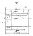
- the initial pressure PA primarily influences the time duration t UReal , while the control pressure is used as the primary influencing factor for the sliding time of the friction elements t slip .
- These indicators are either monitored individually as actual values or in different combinations. There is also the possibility here of using indicators other than these preferred for monitoring. These can be, for example, the time after which the switching process is completed t synchronously , the time after which the safety pressure ramp-up begins and after which the synchronization process should have ended TMAX, or the time after which the operating pressure is present again, T-switching end.
- Another possibility is to change the behavior of the actual values of a Switching process at least indirectly characterizing a size
- a change factor is exceeded, which is the quotient of the change in the manipulated variable and the number the switching processes via which this change behavior is determined, is formed to also generate an error message.
- the diagram shows that after the occurrence of a gearshift signal, in the time axis at time 0 the engine speed n1 increases until a freewheeling point is reached, here point 1, which is the point at which the friction elements assigned to the new gear take full moment while the friction elements assigned to the old gear loosen. From this freewheel point, the engine speed n1 begins to drop, while the friction elements grind at the same time. The time until this freewheeling point is reached, which corresponds to the start of the synchronization process, is denoted by t UREAL . This is followed by the sliding time of the friction elements t SLIDE . In point 2 in the diagram, both friction elements run synchronously, the new gear is engaged, the friction elements stick and the two speeds are either the same or identical according to the step change.
- the shifting comfort is determined by the course of the output torque.
- the moment jump at time t SYNCHRON should be as small as possible.
- the setpoint to be observed for the switching process is the time until the start of the synchronization process t UREAL .
- the manipulated variable for influencing this period is the initial pressure value PA
- the actuator is a device for applying the initial pressure.
- the setpoints for the time until the start of the synchronization process t UREAL are stored, for example, in a load / speed map .
- the grid for the load and speed classes can be chosen arbitrarily, the setpoints being stored in a read-only memory in an electronic transmission control unit.
- measuring devices are provided, which determine the current time during each switching process until the start of the synchronization process.
- the torque per load position, the speed when switching and the moment of inertia of the individual components are taken into account as further influencing parameters. If the measured or determined actual value deviates from the target value, a correction value is output at the output of the control device and is effective at the printing unit. The manipulated variable PA changes by the correction value. The changed initial pressure value is then saved.
- a change in the manipulated variable by a fixed correction value is additive or multiplicative possible.
- the comparator 8 can be implemented, for example, by routines running in the control and regulating device 6.
- the comparator compares, for example, setpoints stored there for the variables at least indirectly characterizing the switching process, here, for example, t UREAL setpoint, with the actual values.
- the comparison can also extend to a predefinable setpoint range.
Landscapes
- Engineering & Computer Science (AREA)
- General Engineering & Computer Science (AREA)
- Mechanical Engineering (AREA)
- Control Of Transmission Device (AREA)
- Testing Of Devices, Machine Parts, Or Other Structures Thereof (AREA)
- Transmitters (AREA)
- Measuring Fluid Pressure (AREA)
Description
Die den Schaltvorgang wenigstens mittelbar charakterisierende Größe kann auch von einer Stellgröße gebildet werden.
- TMAX =
- Zeit; nach der der Sicherheitsdruckhochlauf beginnt und nach deren Ablauf der Synchronisierungsvorgang abgeschlossen sein sollte.
- tUReal =
- Zeitdauer vom Abgeben eines Gangwechselsignals bis zum Beginn der Synchronisation der Reibelemente
- tRutsch =
- Rutschzeit der Reibelemente
- PA =
- Anfangsdruckwert
- PR =
- Regeldruck
- Fig. 1
- anhand eines Schaltverlaufsdiagrammes die Zuordnung von Grenzwerten;
- Fig. 2
- eine Steuereinrichtung zur Durchführung der erfindungsgemäßen Früherkennung.
- USTELLMAX =
- Betriebsdruck
- PR =
- berechneter Regeldruck
- PA =
- Anfangsdruckwert
- PATIME =
- Zeit, in welcher der Anfangsdruckwert auf den Regeldruckwert linear oder degressiv ansteigt oder abfällt
- TMAX =
- Zeit, nach der der Sicherheitsdruckhochlauf beginnt und nach deren Ablauf der Synchronisiervorgang abgeschlossen sein sollte
- TSCHALT-ENDE =
- Zeit, nach der der Betriebsdruck anlegt.
- nSYNCHRON 1 =
- Motordrehzahl bei Beginn des Schaltvorganges
- nSYNCHRON 2 =
- Motordrehzahl nach Beendigung des Schaltvorganges
- tUREAL =
- Zeit bis zu Beginn des Synchronisiervorganges
- tRUTSCH =
- Rutschzeit der Lamellen
- tSYNCHRON =
- Zeit, nach der der Schaltvorgang abgeschlossen wurde.
Claims (9)
- Verfahren zur Früherkennung von Störfällen beim Betrieb automatischer Fahrzeuggetriebe mit elektronisch ansteuerbaren Reibelementen zur Umschaltung zwischen verschiedenen Übersetzungsstufen,1.1 bei welchen ein aktueller Istwert wenigstens einer den Schaltvorgang wenigstens mittelbar charakterisierenden Größen bei jedem Schaltvorgang ermittelt wird;1.2 bei welchem der Istwert mit wenigstens einem Sollwert verglichen wird und bei Abweichung eine Stellgröße zur Beaufschlagung der Reibelemente zur wenigstens mittelbaren Beeinflussung der den Schaltvorgang wenigstens mittelbar charakterisierenden Größen geändert wird;1.3 es ist wenigstens ein Grenzwert für wenigstens eine der nachfolgend genannten Größen festsetzbar:für einen Istwert der den Schaltvorgang wenigstens mittelbar charakterisierenden Größe und/oderfür eine, das Änderungsverhalten des Istwertes über eine Mehrzahl von nacheinander vorgenommenen Schaltvorgängen wenigstens mittelbar charakterisierende Größe und/oderfür die Stellgröße und/oderfür das Änderungsverhalten der Stellgröße über eine Mehrzahl von nacheinander vorgenommenen gleichartigen Schaltvorgängen;1.4 bei welchem bei jedem Schaltvorgang ein Sicherheitsdruckhochtauf beginnt;1.5 dem Grenzwert sind Kriterien hinsichtlich seiner Größe gegenüber dem Istwert oder der Stellgröße zugeordnet;1.6 bei Abweichung des Grenzwertes vom Istwert oder der Stellgröße derart, daß die Kriterien nicht mehr erfüllt sind, wird ein Fehlersignal erzeugt;
dadurch gekenngeichnet, daß1.7 die Zeitdauer, nach deren Ablauf der Synchronisiervorgang abgeschlossen sein sollte und den Sicherheitsdruckhochlauf beginnt als Istwert der den Schaltvorgang charakterisierenden Größe ermittelt wird;1.8 bei welchem bei Abweichung dieser Zeitdauer von einem vorgegebenen Sollzeitraum der Anfangs- und/oder Regeldruckwert als eine Stellgröße zum Aufbringen der erforderlichen Anpreßkraft der kraftschlüssig miteinander koppelbaren Reibelemente um einen Korrekturwert verändert wird. - Verfahren zur Früherkennung von Störfällen nach Anspruch 1, dadurch gekennzeichnet, daß die Änderung der Stellgröße um einen festen unveränderbaren Korrekturwert erfolgt.
- Verfahren zur Früherkennung von Störfällen nach Anspruch 1, dadurch gekennzeichnet, daß die Änderung der Stellgröße um einen berechenbaren Korrekturwert erfolgt.
- Verfahren zur Früherkennung von Störfällen nach Anspruch 3, dadurch gekennzeichnet, daß der Korrekturwert als Mittelwert einer bestimmbaren Vielzahl von hintereinander vorgenommenen gleichartigen Schaltvorgängen ermittelt wird.
- Verfahren zur Früherkennung von Störfällen nach einem der Ansprüche 1 bis 4, dadurch gekennzeichnet, daß das Fehlersignal als Fehlermeldung über ein Display für den Fahrer sichtbar ist.
- Verfahren zur Früherkennung von Störfällen nach einem der Ansprüche 1 bis 5, dadurch gekennzeichnet, daß das Fehlersignal dem Fahrer akustisch übermittelt wird.
- Verfahren zur Früherkennung von Störfällen nach einem der Ansprüche 1 bis 5, dadurch gekennzeichnet, daß das Fehlersignal als Eingangsgröße zur Ansteuerung des Getriebes gesetzt wird.
- Verfahren zur Früherkennung von Störfällen nach einem der Ansprüche 1 bis 7, dadurch gekennzeichnet, daß als Kriterium für den Grenzwert ein bestimmter einzuhaltender Wertebereich festgelegt wird.
- Verfahren zur Früherkennung von Störfällen nach einem der Ansprüche 1 bis 8, dadurch gekennzeichnet, daß der Grenzwert für das Änderungsverhalten des Istwertes einer den Schaltvorgang wenigstens mittelbar charakterisierenden Größe ein bestimmbarer Quotient aus der Anzahl der Korrekturen zur Anzahl gleichartiger nacheinander vorgenommener Umschaltvorgänge ist.
Priority Applications (1)
| Application Number | Priority Date | Filing Date | Title |
|---|---|---|---|
| EP03021364A EP1375980B1 (de) | 1996-12-17 | 1997-12-03 | Verfahren und Vorrichtung zur Früherkennung von Störfällen beim Betrieb automatischer Getriebe |
Applications Claiming Priority (2)
| Application Number | Priority Date | Filing Date | Title |
|---|---|---|---|
| DE19652212 | 1996-12-17 | ||
| DE19652212A DE19652212A1 (de) | 1996-12-17 | 1996-12-17 | Verfahren und Vorrichtung zur Früherkennung von Störfällen beim Betrieb automatischer Getriebe |
Related Child Applications (1)
| Application Number | Title | Priority Date | Filing Date |
|---|---|---|---|
| EP03021364A Division EP1375980B1 (de) | 1996-12-17 | 1997-12-03 | Verfahren und Vorrichtung zur Früherkennung von Störfällen beim Betrieb automatischer Getriebe |
Publications (3)
| Publication Number | Publication Date |
|---|---|
| EP0849505A2 EP0849505A2 (de) | 1998-06-24 |
| EP0849505A3 EP0849505A3 (de) | 1998-10-28 |
| EP0849505B1 true EP0849505B1 (de) | 2004-04-21 |
Family
ID=7814817
Family Applications (2)
| Application Number | Title | Priority Date | Filing Date |
|---|---|---|---|
| EP03021364A Expired - Lifetime EP1375980B1 (de) | 1996-12-17 | 1997-12-03 | Verfahren und Vorrichtung zur Früherkennung von Störfällen beim Betrieb automatischer Getriebe |
| EP97121215A Expired - Lifetime EP0849505B1 (de) | 1996-12-17 | 1997-12-03 | Verfahren und Vorrichtung zur Früherkennung von Störfällen beim Betrieb automatischer Getriebe |
Family Applications Before (1)
| Application Number | Title | Priority Date | Filing Date |
|---|---|---|---|
| EP03021364A Expired - Lifetime EP1375980B1 (de) | 1996-12-17 | 1997-12-03 | Verfahren und Vorrichtung zur Früherkennung von Störfällen beim Betrieb automatischer Getriebe |
Country Status (3)
| Country | Link |
|---|---|
| EP (2) | EP1375980B1 (de) |
| AT (1) | ATE265007T1 (de) |
| DE (2) | DE19652212A1 (de) |
Cited By (1)
| Publication number | Priority date | Publication date | Assignee | Title |
|---|---|---|---|---|
| EP3745000A1 (de) * | 2019-05-28 | 2020-12-02 | WABCO Europe BVBA | Elektromotorischer antriebsstrang einer fahrzeugachse |
Families Citing this family (7)
| Publication number | Priority date | Publication date | Assignee | Title |
|---|---|---|---|---|
| DE10105836C2 (de) | 2001-02-07 | 2003-07-17 | Voith Turbo Kg | Verfahren zur Früherkennung von Störfällen beim Betrieb automatischer oder automatisierter Getriebe |
| DE10212530A1 (de) * | 2002-03-21 | 2003-10-02 | Zahnradfabrik Friedrichshafen | Verfahren zur Steuerung eines Antriebsstrangs eines Kraftfahrzeugs |
| DE10233699A1 (de) * | 2002-07-24 | 2004-02-19 | Voith Turbo Gmbh & Co. Kg | Verfahren und Vorrichtung zur Früherkennung von Störfällen beim Betrieb automatischer oder automatisierter Getriebe |
| JP4082272B2 (ja) * | 2003-05-15 | 2008-04-30 | トヨタ自動車株式会社 | 車両用油圧制御回路の異常判定装置 |
| DE102004001382A1 (de) * | 2004-01-09 | 2005-08-04 | Zf Friedrichshafen Ag | Verfahren zur Erhöhung der Adaptionshäufigkeit bei einem Automatgetriebe |
| EP1815169B1 (de) * | 2004-11-18 | 2010-08-04 | LuK Lamellen und Kupplungsbau Beteiligungs KG | Verfahren zum feststellen einer beschädigung in der schaltaktorik eines automatisierten schaltgetriebes |
| CN112096832B (zh) * | 2020-10-09 | 2022-06-03 | 湖南长峰重工科技有限公司 | 一种自动变速箱换挡系统磨损预警控制方法 |
Family Cites Families (10)
| Publication number | Priority date | Publication date | Assignee | Title |
|---|---|---|---|---|
| DE3205767A1 (de) | 1982-02-18 | 1983-08-25 | Robert Bosch Gmbh, 7000 Stuttgart | Einrichtung zum einstellen des druckes des arbeitsmediums in automatischen stufengetrieben |
| DE3436190C2 (de) | 1984-10-03 | 1995-06-22 | Bosch Gmbh Robert | Einrichtung zur elektronischen Steuerung eines automatischen Fahrzeuggetriebes |
| US4653350A (en) * | 1985-11-29 | 1987-03-31 | General Motors Corporation | Adaptive direct pressure shift control for a motor vehicle transmission |
| JPH0781627B2 (ja) * | 1988-02-05 | 1995-09-06 | 日産自動車株式会社 | 自動変速機のライン圧制御装置 |
| EP0435372B1 (de) | 1989-12-26 | 1994-11-09 | General Motors Corporation | Verfahren zum Steuern des Gangwechsels in automatischen Getrieben |
| US5182970A (en) * | 1990-04-04 | 1993-02-02 | Aisin Seiki Kabushiki Kaisha | Hydraulic control system for automatic transmission |
| DE4110910C2 (de) * | 1990-04-05 | 1995-04-27 | Aisin Seiki | Hydraulisches Steuerungssystem für ein Automatikgetriebe |
| DE4217270A1 (de) * | 1992-05-25 | 1993-12-02 | Opel Adam Ag | Verfahren zur Korrektur der Schaltqualität eines automatischen Getriebes |
| GB2286641B (en) * | 1994-02-17 | 1998-01-07 | Acg France | Method and apparatus for controlling a gear change in an automatic transmission |
| DE19531675A1 (de) * | 1995-08-29 | 1997-03-06 | Voith Gmbh J M | Verfahren zum Betreiben eines Fahrzeuggetriebes |
-
1996
- 1996-12-17 DE DE19652212A patent/DE19652212A1/de not_active Withdrawn
-
1997
- 1997-12-03 DE DE59711540T patent/DE59711540D1/de not_active Expired - Lifetime
- 1997-12-03 EP EP03021364A patent/EP1375980B1/de not_active Expired - Lifetime
- 1997-12-03 AT AT97121215T patent/ATE265007T1/de active
- 1997-12-03 EP EP97121215A patent/EP0849505B1/de not_active Expired - Lifetime
Cited By (2)
| Publication number | Priority date | Publication date | Assignee | Title |
|---|---|---|---|---|
| EP3745000A1 (de) * | 2019-05-28 | 2020-12-02 | WABCO Europe BVBA | Elektromotorischer antriebsstrang einer fahrzeugachse |
| DE102019114290A1 (de) * | 2019-05-28 | 2020-12-03 | Wabco Europe Bvba | Elektromotorischer Antriebsstrang einer Fahrzeugachse |
Also Published As
| Publication number | Publication date |
|---|---|
| EP1375980A3 (de) | 2006-09-20 |
| ATE265007T1 (de) | 2004-05-15 |
| EP0849505A3 (de) | 1998-10-28 |
| DE59711540D1 (de) | 2004-05-27 |
| EP0849505A2 (de) | 1998-06-24 |
| DE19652212A1 (de) | 1998-06-18 |
| EP1375980A2 (de) | 2004-01-02 |
| EP1375980B1 (de) | 2012-06-13 |
Similar Documents
| Publication | Publication Date | Title |
|---|---|---|
| DE4118736C2 (de) | Steuervorrichtung | |
| DE102004022929B4 (de) | Störungserfassungsvorrichtung für einen Hydraulikdrucksteuerkreis eines Fahrzeugs | |
| DE102011017516B4 (de) | Verfahren zur Bestimmung von Kenngrößen eines Automatikgetriebes | |
| DE10057855B4 (de) | Schaltungssteuersystem eines hydraulisch stufenlos veränderbaren Getriebes für ein Kraftfahrzeug | |
| EP1098785B1 (de) | Verfahren zur einstellung einer übersetzung eines stufenlosen automatgetriebes mit einem variator | |
| EP0651182A2 (de) | Verfahren zum Steuern einer die Drehzahldifferenz einer Kupplung eines Kraftfahrzeuges bestimmenden Stellgrösse | |
| DE102004009833A1 (de) | Verfahren zur Steuerung einer Kupplung | |
| DE10346922B4 (de) | Vorrichtung und Verfahren zur Fehlerermittlung bei einem automatischen Getriebe | |
| EP1375980B1 (de) | Verfahren und Vorrichtung zur Früherkennung von Störfällen beim Betrieb automatischer Getriebe | |
| DE10035005B4 (de) | Verfahren und Vorrichtung zur Regelung der Übersetzung eines Getriebes mit stufenlos veränderbarer Übersetzung | |
| DE10105836C2 (de) | Verfahren zur Früherkennung von Störfällen beim Betrieb automatischer oder automatisierter Getriebe | |
| DE10038379A1 (de) | Automatikgetriebe vom Gangtyp und Verfahren zum Steuern desselben | |
| EP1584832B1 (de) | Verfahren zum Ansteuern des Kupplungsmomentes einer Kupplung eines automatisierten Getriebes und eine Vorrichtung zum Durchführen des Verfahrens | |
| EP0929409A1 (de) | Vorrichtung und verfahren zur übersetzungsverstellung bei einem cvt | |
| EP1259789A1 (de) | Verfahren zum bestimmen eines reibwerts | |
| DE19815258A1 (de) | Kraftfahrzeug mit einer automatisierten Kupplung | |
| DE29621791U1 (de) | Vorrichtung zur Früherkennung von Störfällen beim Betrieb automatischer Getriebe | |
| DE102016215217A1 (de) | Verfahren zum Betätigen eines elektrohydraulischen Getriebesteuersystems eines Doppelkupplungsgetriebes | |
| DE102017009531B4 (de) | Verfahren zum Betreiben eines schlupfgeregelten Systems eines Antriebsstrangs für ein Kraftfahrzeug | |
| DE10231820A1 (de) | Verfahren zur Bestimmung von Kenngrößen eines Getriebes | |
| WO2019096522A1 (de) | Verfahren zum kalibrieren eines kennfelds einer arbeitsmaschine sowie arbeitsmaschine | |
| DE19638078C2 (de) | Fahrzeuggetriebe mit Absenkung des Antriebsmomentes beim Schalten | |
| DE10233699A1 (de) | Verfahren und Vorrichtung zur Früherkennung von Störfällen beim Betrieb automatischer oder automatisierter Getriebe | |
| DE102006050957A1 (de) | Kraftfahrzeugantrieb | |
| DE19757317A1 (de) | Überwachen des einwandfreien Arbeitens eines automatischen Getriebes |
Legal Events
| Date | Code | Title | Description |
|---|---|---|---|
| PUAI | Public reference made under article 153(3) epc to a published international application that has entered the european phase |
Free format text: ORIGINAL CODE: 0009012 |
|
| AK | Designated contracting states |
Kind code of ref document: A2 Designated state(s): AT DE FR GB IT SE |
|
| AX | Request for extension of the european patent |
Free format text: AL;LT;LV;MK;RO;SI |
|
| PUAL | Search report despatched |
Free format text: ORIGINAL CODE: 0009013 |
|
| AK | Designated contracting states |
Kind code of ref document: A3 Designated state(s): AT BE CH DE DK ES FI FR GB GR IE IT LI LU MC NL PT SE |
|
| AX | Request for extension of the european patent |
Free format text: AL;LT;LV;MK;RO;SI |
|
| 17P | Request for examination filed |
Effective date: 19990305 |
|
| AKX | Designation fees paid |
Free format text: AT DE FR GB IT SE |
|
| 17Q | First examination report despatched |
Effective date: 20020228 |
|
| GRAP | Despatch of communication of intention to grant a patent |
Free format text: ORIGINAL CODE: EPIDOSNIGR1 |
|
| GRAS | Grant fee paid |
Free format text: ORIGINAL CODE: EPIDOSNIGR3 |
|
| GRAA | (expected) grant |
Free format text: ORIGINAL CODE: 0009210 |
|
| AK | Designated contracting states |
Kind code of ref document: B1 Designated state(s): AT DE FR GB IT SE |
|
| REG | Reference to a national code |
Ref country code: GB Ref legal event code: FG4D Free format text: NOT ENGLISH |
|
| GBT | Gb: translation of ep patent filed (gb section 77(6)(a)/1977) |
Effective date: 20040421 |
|
| REF | Corresponds to: |
Ref document number: 59711540 Country of ref document: DE Date of ref document: 20040527 Kind code of ref document: P |
|
| REG | Reference to a national code |
Ref country code: SE Ref legal event code: TRGR |
|
| ET | Fr: translation filed | ||
| PLBE | No opposition filed within time limit |
Free format text: ORIGINAL CODE: 0009261 |
|
| STAA | Information on the status of an ep patent application or granted ep patent |
Free format text: STATUS: NO OPPOSITION FILED WITHIN TIME LIMIT |
|
| 26N | No opposition filed |
Effective date: 20050124 |
|
| PGFP | Annual fee paid to national office [announced via postgrant information from national office to epo] |
Ref country code: IT Payment date: 20121218 Year of fee payment: 16 Ref country code: GB Payment date: 20121227 Year of fee payment: 16 |
|
| PGFP | Annual fee paid to national office [announced via postgrant information from national office to epo] |
Ref country code: AT Payment date: 20121219 Year of fee payment: 16 |
|
| PGFP | Annual fee paid to national office [announced via postgrant information from national office to epo] |
Ref country code: SE Payment date: 20121227 Year of fee payment: 16 Ref country code: DE Payment date: 20130128 Year of fee payment: 16 Ref country code: FR Payment date: 20130117 Year of fee payment: 16 |
|
| REG | Reference to a national code |
Ref country code: DE Ref legal event code: R119 Ref document number: 59711540 Country of ref document: DE |
|
| REG | Reference to a national code |
Ref country code: SE Ref legal event code: EUG |
|
| REG | Reference to a national code |
Ref country code: AT Ref legal event code: MM01 Ref document number: 265007 Country of ref document: AT Kind code of ref document: T Effective date: 20131203 |
|
| GBPC | Gb: european patent ceased through non-payment of renewal fee |
Effective date: 20131203 |
|
| PG25 | Lapsed in a contracting state [announced via postgrant information from national office to epo] |
Ref country code: SE Free format text: LAPSE BECAUSE OF NON-PAYMENT OF DUE FEES Effective date: 20131204 |
|
| REG | Reference to a national code |
Ref country code: FR Ref legal event code: ST Effective date: 20140829 |
|
| REG | Reference to a national code |
Ref country code: DE Ref legal event code: R119 Ref document number: 59711540 Country of ref document: DE Effective date: 20140701 |
|
| PG25 | Lapsed in a contracting state [announced via postgrant information from national office to epo] |
Ref country code: DE Free format text: LAPSE BECAUSE OF NON-PAYMENT OF DUE FEES Effective date: 20140701 |
|
| PG25 | Lapsed in a contracting state [announced via postgrant information from national office to epo] |
Ref country code: FR Free format text: LAPSE BECAUSE OF NON-PAYMENT OF DUE FEES Effective date: 20131231 Ref country code: AT Free format text: LAPSE BECAUSE OF NON-PAYMENT OF DUE FEES Effective date: 20131203 Ref country code: GB Free format text: LAPSE BECAUSE OF NON-PAYMENT OF DUE FEES Effective date: 20131203 |
|
| PG25 | Lapsed in a contracting state [announced via postgrant information from national office to epo] |
Ref country code: IT Free format text: LAPSE BECAUSE OF NON-PAYMENT OF DUE FEES Effective date: 20131231 |
|
| PG25 | Lapsed in a contracting state [announced via postgrant information from national office to epo] |
Ref country code: IT Free format text: LAPSE BECAUSE OF NON-PAYMENT OF DUE FEES Effective date: 20131203 |