EP0848146B1 - Control apparatus for an in-cylinder injection type internal combustion engine - Google Patents
Control apparatus for an in-cylinder injection type internal combustion engine Download PDFInfo
- Publication number
- EP0848146B1 EP0848146B1 EP97121748A EP97121748A EP0848146B1 EP 0848146 B1 EP0848146 B1 EP 0848146B1 EP 97121748 A EP97121748 A EP 97121748A EP 97121748 A EP97121748 A EP 97121748A EP 0848146 B1 EP0848146 B1 EP 0848146B1
- Authority
- EP
- European Patent Office
- Prior art keywords
- intake
- engine
- fuel
- air
- induction
- Prior art date
- Legal status (The legal status is an assumption and is not a legal conclusion. Google has not performed a legal analysis and makes no representation as to the accuracy of the status listed.)
- Expired - Lifetime
Links
Images


Classifications
-
- F—MECHANICAL ENGINEERING; LIGHTING; HEATING; WEAPONS; BLASTING
- F02—COMBUSTION ENGINES; HOT-GAS OR COMBUSTION-PRODUCT ENGINE PLANTS
- F02D—CONTROLLING COMBUSTION ENGINES
- F02D41/00—Electrical control of supply of combustible mixture or its constituents
- F02D41/02—Circuit arrangements for generating control signals
- F02D41/04—Introducing corrections for particular operating conditions
-
- F—MECHANICAL ENGINEERING; LIGHTING; HEATING; WEAPONS; BLASTING
- F02—COMBUSTION ENGINES; HOT-GAS OR COMBUSTION-PRODUCT ENGINE PLANTS
- F02D—CONTROLLING COMBUSTION ENGINES
- F02D41/00—Electrical control of supply of combustible mixture or its constituents
- F02D41/30—Controlling fuel injection
- F02D41/3011—Controlling fuel injection according to or using specific or several modes of combustion
- F02D41/3017—Controlling fuel injection according to or using specific or several modes of combustion characterised by the mode(s) being used
- F02D41/3023—Controlling fuel injection according to or using specific or several modes of combustion characterised by the mode(s) being used a mode being the stratified charge spark-ignited mode
-
- F—MECHANICAL ENGINEERING; LIGHTING; HEATING; WEAPONS; BLASTING
- F01—MACHINES OR ENGINES IN GENERAL; ENGINE PLANTS IN GENERAL; STEAM ENGINES
- F01D—NON-POSITIVE DISPLACEMENT MACHINES OR ENGINES, e.g. STEAM TURBINES
- F01D15/00—Adaptations of machines or engines for special use; Combinations of engines with devices driven thereby
- F01D15/10—Adaptations for driving, or combinations with, electric generators
-
- F—MECHANICAL ENGINEERING; LIGHTING; HEATING; WEAPONS; BLASTING
- F01—MACHINES OR ENGINES IN GENERAL; ENGINE PLANTS IN GENERAL; STEAM ENGINES
- F01D—NON-POSITIVE DISPLACEMENT MACHINES OR ENGINES, e.g. STEAM TURBINES
- F01D5/00—Blades; Blade-carrying members; Heating, heat-insulating, cooling or antivibration means on the blades or the members
- F01D5/02—Blade-carrying members, e.g. rotors
- F01D5/08—Heating, heat-insulating or cooling means
- F01D5/085—Heating, heat-insulating or cooling means cooling fluid circulating inside the rotor
-
- F—MECHANICAL ENGINEERING; LIGHTING; HEATING; WEAPONS; BLASTING
- F02—COMBUSTION ENGINES; HOT-GAS OR COMBUSTION-PRODUCT ENGINE PLANTS
- F02B—INTERNAL-COMBUSTION PISTON ENGINES; COMBUSTION ENGINES IN GENERAL
- F02B17/00—Engines characterised by means for effecting stratification of charge in cylinders
- F02B17/005—Engines characterised by means for effecting stratification of charge in cylinders having direct injection in the combustion chamber
-
- F—MECHANICAL ENGINEERING; LIGHTING; HEATING; WEAPONS; BLASTING
- F02—COMBUSTION ENGINES; HOT-GAS OR COMBUSTION-PRODUCT ENGINE PLANTS
- F02B—INTERNAL-COMBUSTION PISTON ENGINES; COMBUSTION ENGINES IN GENERAL
- F02B27/00—Use of kinetic or wave energy of charge in induction systems, or of combustion residues in exhaust systems, for improving quantity of charge or for increasing removal of combustion residues
- F02B27/02—Use of kinetic or wave energy of charge in induction systems, or of combustion residues in exhaust systems, for improving quantity of charge or for increasing removal of combustion residues the systems having variable, i.e. adjustable, cross-sectional areas, chambers of variable volume, or like variable means
- F02B27/0205—Use of kinetic or wave energy of charge in induction systems, or of combustion residues in exhaust systems, for improving quantity of charge or for increasing removal of combustion residues the systems having variable, i.e. adjustable, cross-sectional areas, chambers of variable volume, or like variable means characterised by the charging effect
- F02B27/0215—Oscillating pipe charging, i.e. variable intake pipe length charging
-
- F—MECHANICAL ENGINEERING; LIGHTING; HEATING; WEAPONS; BLASTING
- F02—COMBUSTION ENGINES; HOT-GAS OR COMBUSTION-PRODUCT ENGINE PLANTS
- F02B—INTERNAL-COMBUSTION PISTON ENGINES; COMBUSTION ENGINES IN GENERAL
- F02B37/00—Engines characterised by provision of pumps driven at least for part of the time by exhaust
- F02B37/02—Gas passages between engine outlet and pump drive, e.g. reservoirs
- F02B37/025—Multiple scrolls or multiple gas passages guiding the gas to the pump drive
-
- F—MECHANICAL ENGINEERING; LIGHTING; HEATING; WEAPONS; BLASTING
- F02—COMBUSTION ENGINES; HOT-GAS OR COMBUSTION-PRODUCT ENGINE PLANTS
- F02B—INTERNAL-COMBUSTION PISTON ENGINES; COMBUSTION ENGINES IN GENERAL
- F02B37/00—Engines characterised by provision of pumps driven at least for part of the time by exhaust
- F02B37/04—Engines with exhaust drive and other drive of pumps, e.g. with exhaust-driven pump and mechanically-driven second pump
- F02B37/10—Engines with exhaust drive and other drive of pumps, e.g. with exhaust-driven pump and mechanically-driven second pump at least one pump being alternatively or simultaneously driven by exhaust and other drive, e.g. by pressurised fluid from a reservoir or an engine-driven pump
-
- F—MECHANICAL ENGINEERING; LIGHTING; HEATING; WEAPONS; BLASTING
- F02—COMBUSTION ENGINES; HOT-GAS OR COMBUSTION-PRODUCT ENGINE PLANTS
- F02B—INTERNAL-COMBUSTION PISTON ENGINES; COMBUSTION ENGINES IN GENERAL
- F02B39/00—Component parts, details, or accessories relating to, driven charging or scavenging pumps, not provided for in groups F02B33/00 - F02B37/00
- F02B39/005—Cooling of pump drives
-
- F—MECHANICAL ENGINEERING; LIGHTING; HEATING; WEAPONS; BLASTING
- F02—COMBUSTION ENGINES; HOT-GAS OR COMBUSTION-PRODUCT ENGINE PLANTS
- F02B—INTERNAL-COMBUSTION PISTON ENGINES; COMBUSTION ENGINES IN GENERAL
- F02B39/00—Component parts, details, or accessories relating to, driven charging or scavenging pumps, not provided for in groups F02B33/00 - F02B37/00
- F02B39/02—Drives of pumps; Varying pump drive gear ratio
- F02B39/08—Non-mechanical drives, e.g. fluid drives having variable gear ratio
- F02B39/10—Non-mechanical drives, e.g. fluid drives having variable gear ratio electric
-
- F—MECHANICAL ENGINEERING; LIGHTING; HEATING; WEAPONS; BLASTING
- F02—COMBUSTION ENGINES; HOT-GAS OR COMBUSTION-PRODUCT ENGINE PLANTS
- F02B—INTERNAL-COMBUSTION PISTON ENGINES; COMBUSTION ENGINES IN GENERAL
- F02B39/00—Component parts, details, or accessories relating to, driven charging or scavenging pumps, not provided for in groups F02B33/00 - F02B37/00
- F02B39/14—Lubrication of pumps; Safety measures therefor
-
- F—MECHANICAL ENGINEERING; LIGHTING; HEATING; WEAPONS; BLASTING
- F02—COMBUSTION ENGINES; HOT-GAS OR COMBUSTION-PRODUCT ENGINE PLANTS
- F02B—INTERNAL-COMBUSTION PISTON ENGINES; COMBUSTION ENGINES IN GENERAL
- F02B75/00—Other engines
- F02B75/12—Other methods of operation
- F02B2075/125—Direct injection in the combustion chamber for spark ignition engines, i.e. not in pre-combustion chamber
-
- F—MECHANICAL ENGINEERING; LIGHTING; HEATING; WEAPONS; BLASTING
- F02—COMBUSTION ENGINES; HOT-GAS OR COMBUSTION-PRODUCT ENGINE PLANTS
- F02B—INTERNAL-COMBUSTION PISTON ENGINES; COMBUSTION ENGINES IN GENERAL
- F02B2275/00—Other engines, components or details, not provided for in other groups of this subclass
- F02B2275/18—DOHC [Double overhead camshaft]
-
- F—MECHANICAL ENGINEERING; LIGHTING; HEATING; WEAPONS; BLASTING
- F02—COMBUSTION ENGINES; HOT-GAS OR COMBUSTION-PRODUCT ENGINE PLANTS
- F02B—INTERNAL-COMBUSTION PISTON ENGINES; COMBUSTION ENGINES IN GENERAL
- F02B27/00—Use of kinetic or wave energy of charge in induction systems, or of combustion residues in exhaust systems, for improving quantity of charge or for increasing removal of combustion residues
- F02B27/02—Use of kinetic or wave energy of charge in induction systems, or of combustion residues in exhaust systems, for improving quantity of charge or for increasing removal of combustion residues the systems having variable, i.e. adjustable, cross-sectional areas, chambers of variable volume, or like variable means
- F02B27/0226—Use of kinetic or wave energy of charge in induction systems, or of combustion residues in exhaust systems, for improving quantity of charge or for increasing removal of combustion residues the systems having variable, i.e. adjustable, cross-sectional areas, chambers of variable volume, or like variable means characterised by the means generating the charging effect
- F02B27/0268—Valves
- F02B27/0273—Flap valves
-
- F—MECHANICAL ENGINEERING; LIGHTING; HEATING; WEAPONS; BLASTING
- F05—INDEXING SCHEMES RELATING TO ENGINES OR PUMPS IN VARIOUS SUBCLASSES OF CLASSES F01-F04
- F05D—INDEXING SCHEME FOR ASPECTS RELATING TO NON-POSITIVE-DISPLACEMENT MACHINES OR ENGINES, GAS-TURBINES OR JET-PROPULSION PLANTS
- F05D2220/00—Application
- F05D2220/40—Application in turbochargers
-
- Y—GENERAL TAGGING OF NEW TECHNOLOGICAL DEVELOPMENTS; GENERAL TAGGING OF CROSS-SECTIONAL TECHNOLOGIES SPANNING OVER SEVERAL SECTIONS OF THE IPC; TECHNICAL SUBJECTS COVERED BY FORMER USPC CROSS-REFERENCE ART COLLECTIONS [XRACs] AND DIGESTS
- Y02—TECHNOLOGIES OR APPLICATIONS FOR MITIGATION OR ADAPTATION AGAINST CLIMATE CHANGE
- Y02T—CLIMATE CHANGE MITIGATION TECHNOLOGIES RELATED TO TRANSPORTATION
- Y02T10/00—Road transport of goods or passengers
- Y02T10/10—Internal combustion engine [ICE] based vehicles
- Y02T10/12—Improving ICE efficiencies
Definitions
- the present invention relates to an in-cylinder injection type internal combustion engine, and more particularly, to a control apparatus for an engine of this type which apparatus makes a stratified degree of the intake air flow generated in a combustion chamber suitable for a fuel injection mode, to thereby improve the fuel consumption and output of the engine.
- a spark-ignition type multi-cylinder internal combustion engine is provided with an induction system comprising an intake pipe in which a throttle valve is disposed and an intake manifold through which the intake air supplied from the intake pipe is distributed to respective cylinders of the engine.
- the vertical motions of pistons in the cylinders and the opening/closing actions of intake valves cause the air pressure in the induction system to periodically vary.
- the induction system is designed to improve the induction efficiency.
- a surge tank is provided between the intake pipe and the intake manifold.
- the induction system is configured to attain the supercharging effect of inertial induction and pulsating induction.
- an optimum length of the intake pipe for attainment of the supercharging effect varies depending on engine speed, whereas the intake pipe usually has a fixed length. Thus, it is difficult to attain the supercharging effect over the entire engine speed region.
- an induction control system which changes the effective length of the intake manifold in two stages, by opening and closing an induction control valve to cause the effective-length increasing function of a detour induction passage, interposed between upstream portion and downstream portion of the intake manifold, to be selectively effective.
- This system closes the induction control valve to cause the intake air to flow from the upstream portion into the downstream portion of the intake manifold by way of the detour induction passage when the engine is in a low-speed region, and opens the valve to cause the air to bypass the detour passage so that the air flows directly into the downstream portion of the intake manifold.
- a typical in-cylinder injection type engine is arranged to inject fuel from a fuel injection valve into a cavity formed in the top of a piston of the engine when the engine is in a low-load region, to thereby form a substantially stoichiometric air-fuel mixture around an ignition plug at ignition timing and form a lean mixture around the substantially stoichiometric mixture.
- a technique of generating a circling flow e.g., a so-called tumble flow or swirl flow
- a substantially stoichiometric air-fuel mixture is retained in the cavity under the action of the circling flow of intake air.
- EP-A-661 432 relates to an internal combustion engine of the type in which the fuel is injected directly into a cylinder.
- EP-A-661 432 discloses a technical art in which, under a partial load, a pumping loss is reduced by a stratified combustion to enhance a fuel consumption, and during the maximum output operation, the output is increased by a premixture combustion, and the output of an engine is controlled, thereby enhancing the drivability, and in which, when the air/fuel ratio is changed over, the throttle valve opening or the amount of a valve lift is controlled so as to vary an amount of intake air, thereby preventing the output torque from being varied.
- the throttle valve opening is controlled so as to produce a proper turbulence in a cylinder.
- an induction control system In order to further improve the fuel consumption and output of an in-cylinder injection type internal combustion engine, the present inventors attempted to utilize an induction control system. According to experiments, it was found that a stabilized combustion could not be achieved depending on a combination of fuel injection mode of the engine and an operating mode (effective intake pipe length) of the induction control system. For instance, in the case of using an induction control system provided with a detour induction passage which has a considerable length for the passage length adjustment and a complicated shape for avoiding interference with peripheral components, a stable combustion could not be attained, if the effective pipe length was made long at the time of engine operation in the compression-stroke injection mode.
- a strong circling flow of intake air must be generated to enhance a stratified degree of intake air flow, thereby increasing the degree of stratified charging. It is considered that the reason why the combustion cannot be stabilized resides in that the circling flow strong enough to attain a desired stratified degree of intake air flow cannot be generated.
- the strength of circling flow is represented, e.g., by a circling flow ratio (which is a ratio of the rotational speed of circling flow to the engine rotational speed). The strength of circling flow becomes greater as the circling flow ratio increases.
- the circling flow enhances the uniformity of air-fuel mixture in the cylinder, but the strength of the circling flow does not greatly affect the stability of combustion.
- An object of the present invention is to provide a control apparatus for an in-cylinder injection type internal combustion engine, which apparatus can make the stratified degree of intake air flow suitable for the fuel injection mode, thereby improving the fuel consumption and output of the engine.
- a control apparatus of an in-cylinder injection type internal combustion engine which is selectively operated in at least either a compression-stroke injection mode where fuel is injected in a compression stroke or an intake-stroke injection mode where the fuel is injected in an intake stroke of the engine.
- the control apparatus of this invention comprises an air flow changing system for introducing air into a combustion chamber of the engine and for changing a flow of the air, and stratified-degree changing means for operating the air flow changing system in accordance with the selected injection mode, to thereby change a stratified degree of an intake air flow which is generated by the air introduced into the combustion chamber.
- the stratified-degree changing means operates the air flow changing system so as to enhance the stratified degree of the intake air flow.
- the present invention is advantageous in that the stratified degree of the intake air flow is made suitable for the fuel injection mode (engine operating state), to thereby attain a stable combustion in an in-cylinder injection type internal combustion engine, whereby the fuel consumption and output of the engine can be improved.
- the present invention makes it possible to change the flow of air in the induction system so as to enhance the stratified degree of the intake air flow when the engine is operated in the compression-stroke injection mode in which a combustion is liable to be affected by the stratified degree of the intake air flow.
- the stratified charging can be stabilized for stable stratified combustion.
- the air flow changing system has an induction passage through which the air flows, and operates to change an effective length of the induction passage. More preferably, when the internal combustion engine is operated in the compression-stroke injection mode, the stratified-degree changing means causes the air flow changing system to operate to shorten or lengthen the effective length of the induction passage, thereby enhancing the stratified degree of the intake air flow.
- the induction passage length can be changed to an optimum length suitable for the injection mode, to thereby attain a desired stratified degree of the intake air flow suited to the injection mode.
- the induction passage length can be lengthened when the engine is operated in the compression-stroke injection mode.
- the induction passage length can be shortened in case that an air flow changing system is employed which is designed to establish a smooth air flow in a condition that the induction passage is short in length.
- the stratified degree of the intake air flow in the compression-stroke injection mode is enhanced, to thereby attain a stable combustion and an improved fuel efficiency.
- the volumetric efficiency can be improved in the compression-stroke injection mode, whereby the engine output and combustion stability can be further enhanced.
- a spark-ignition, in-cylinder injection type internal combustion engine (hereinafter referred to as engine) on which a control apparatus according to a first embodiment of this invention is mounted will be explained.
- the engine 1 has a cylinder head 2 thereof fitted with a spark plug 3 and an electromagnetic fuel injection valve 4 for each cylinder, so that fuel may be injected from the fuel injection valve 4 directly into a combustion chamber 5 concerned.
- a hemispherical cavity 8 is formed in the top surface of a piston 7 disposed in the cylinder 6 for reciprocal motion. The cavity is located at a position to which fuel spray can reach if the fuel is injected from the fuel injection valve 4 at timing in a latter stage of the compression stroke of the engine.
- the theoretical compression ratio of the engine 1 is set to a value (in this embodiment, approximately 12) higher than that of an intake-manifold injection type engine.
- a DOHC four-valve system is employed as a valve driving mechanism. Intake-side and exhaust-side camshafts 11 and 12 for driving intake and exhaust valves 9 and 10 are rotatably held at an upper portion of the cylinder head 2.
- the cylinder head 2 is formed with intake ports 13 which extend substantially upright between the camshafts 11 and 12. Intake air flow having passed through the intake port 13 can generate a tumble flow in the combustion chamber 5. Exhaust ports 14 extend substantially in the horizontal direction, as in the case of those of ordinary engines. A large-diameter EGR port 15 diverges diagonally downward from the exhaust port concerned.
- the engine 1 is provided with a water temperature sensor 16 for detecting a cooling water temperature Tw, a crank angle sensor 17 for outputting a crank angle signal SGT at predetermined crank positions for each cylinder and for detecting the engine rotational speed Ne based on the crank angle signal SGT. Further, an ignition coil 19 for supplying a high voltage to the spark plug 3 is provided.
- One of the camshafts which rotate at half the speed of the crankshaft, is fitted with a cylinder discriminating sensor (not shown) for outputting a cylinder discriminating signal SGC, whereby the cylinder for which the crank angle signal SGT is output is discriminated based on the sensor signal SGC.
- the intake ports 13 are connected, through an intake manifold 21, with an intake pipe 25 which is provided with a throttle body 23, a first air bypass valve (#1ABV) 24 of a stepper-motor type serving as intake-air amount correction means, and an air cleaner 22.
- the intake pipe 25 is further provided with a large-diameter air bypass pipe 26 through which intake air is introduced, bypassing the throttle body 23, to the intake manifold 21 and in which a second air bypass valve (#2ABV) 27 of a large linear-solenoid type is disposed.
- the air bypass pipe 26 has a flow area substantially equal to that of the intake pipe 25, so that a quantity of intake air, required for engine operation in a low or medium speed region, can flow through the pipe 26 when the second air bypass valve 27 is fully open.
- the first air bypass valve 24 has a flow area smaller than that of the second air bypass valve 27 and is used to finely adjust the intake air amount.
- the throttle body 23 is provided with a butterfly type throttle valve 28 for opening and closing the intake passage formed therein, a throttle position sensor 29 for detecting the throttle opening degree ⁇ th, and an idle switch 30 for detecting a fully-closed state of the throttle valve 28, i.e., an idle state of the engine.
- An intake air temperature sensor and an atmospheric pressure sensor (none of which is shown), for determining the density of intake air are disposed in the air cleaner 22. These sensors deliver output signals indicative of the atmospheric pressure and the intake air temperature, respectively.
- a Karman's vortex type air flow sensor 32 is disposed and outputs a vortex occurrence signal which is proportional to the volumetric air flow rate Qa per intake stroke.
- a boost pressure sensor not shown, for detecting the intake air pressure within the intake pipe 25 may be provided.
- the engine 1 is provided with a control apparatus which operates to make a stratified degree of intake air flow, generated by air introduced into the combustion chamber, suitable for the fuel injection mode.
- the control apparatus includes an air flow changing system for changing the flow of the air in the induction system of the engine 1, and stratified-degree changing means for operating the air flow changing system in accordance with the injection mode to thereby change the stratified degree of the intake air flow.
- the stratified degree changing means is constituted by the below-mentioned electronic control unit (ECU) 70
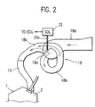
- the air flow changing system is constituted by an induction control system 18 which is of an effective pipe length changing type.
- the induction control system 18 includes a first induction pipe 18a which constitutes a downstream portion of the intake pipe 25.
- a downstream end portion of the first pipe 18a constitutes a surge tank.
- the first pipe 18a has a downstream end thereof connected with upstream ends of second induction pipes (detour pipes).
- second induction pipes denoted by reference numeral 18b.
- Sections where the pipes 18a and 18b are connected with each other are referred to as first communicating sections.
- the downstream end of the first pipe 18a is connected with upstream ends of third induction pipes which cooperate with the second pipes 18b to constitute the intake manifold 21 whose effective length is variable.
- One of the third pipes is shown by reference numeral 18c.
- Induction control valves for selectively permitting or prohibiting the communication between the first pipe 18a and the third pipes 18c are disposed at the second communication sections.
- the downstream ends of the second pipes 18b are connected to the upstream ends of the third pipes 18c whose downstream ends are connected to the upstream ends of the intake ports 13 for the respective cylinders of the engine 1.
- the pipes 18a, 18b and 18c of the induction control system 18 are disposed so as not to interfere with various components disposed in the engine room of a vehicle on which the engine 1 is installed and with the bonnet hood of the vehicle.
- the second pipes 18b must satisfy additional requirements such that they must be formed into a shape which permits their upstream and downstream ends to be connected with the downstream ends of the third pipes 18c and their lengths are long enough to exhibit the function of increasing the effective length of the intake manifold 21.
- each of the second pipes 18b has a considerable length, has a bent or curved shape as viewed in the lengthwise direction of the pipe 18b, and has a cross section which varies in shape at different lengthwise positions of the pipe 18b.
- the air receives a large resistance when it flows through the pipe 18b.
- the induction control system is disposed between the right and left cylinder banks of the engine.
- the second pipe 18b must be formed into a further complicated shape where the cross-sectional area of the pipe greatly varies along its lengthwise direction.
- the first and third pipes 18a and 18c are less likely to be bent and are hence small in change in its cross-sectional shape.
- the induction control valve 18d disposed at the second communicating section where the pipes 18a and 18c are connected with each other, is coupled to a movable rod 33a of a solenoid 33 through a coupling member such as a lever, not shown.
- the solenoid 33 includes an excitation coil electrically connected with the output side of an electric control unit (ECU) 70.
- the induction control valve 18d takes an ON position (shown by broken line in FIG. 2) where it permits the communication between the pipes 18a and 18c to be established when the excitation coil of the solenoid 33 is energized, and takes an OFF position (shown by solid line in FIG. 2) where it prohibits the communication therebetween when the excitation coil is de-energized, for instance.
- the induction control valve 18d When the induction control valve 18d is in the OFF position, the first pipe 18a is connected through the second pipe 18b with the third pipe 18c, so that the length of the intake manifold 21 (more generally, the length of the intake passage of the induction system) becomes long.
- the air supplied from the intake pipe 25 flows along the induction route constituted by the pipes 18a, 18b and 18c, as shown by solid arrow in FIG. 2.
- the flow of the air passing through the induction passage of the induction control system 18 is unsmoothed by a degree corresponding to the induction resistance of the second pipe 18b, so that the strength of the tumble air flow formed in the combustion chamber 5 is weakened.
- the induction control valve 18d when the induction control valve 18d is at the ON position, the second pipe 18b is short-circuited, so that the first pipe 18a is connected directly with the third pipe 18c.
- the length of the intake manifold 21 is shortened, and a bend in the resultant induction passage defined in the intake manifold 21 is relatively lessened and hence a change in the cross-sectional area of this passage is relatively small.
- the intake air flows along the route comprised of the first and third pipes 18a and 18c, as shown by broken arrow in FIG. 2.
- the air flow passing through the induction passage defined at this time in the induction control system 18 is smoothed by a degree corresponding to the eliminated induction resistance of the second pipe 18b, so that the resultant tumble flow is strengthened.
- the Exhaust ports 14 are connected, through an exhaust manifold 41 provided with an O 2 sensor 40, to an exhaust pipe 43 which is provided with a three way catalyst 42, a muffler (not shown) and the like.
- the aforementioned EGR ports 15 are connected to the downstream of the throttle valve 28 and the upstream of the intake manifold 21 through a large-diameter EGR pipe 44 in which a stepper-motor type EGR valve 45 is provided.
- the fuel stored in a fuel tank 50 is sucked up by a motor-operated low-pressure fuel pump 51, and is supplied to the engine 1 through a low-pressure feed pipe 52.
- the pressure of the fuel in the low-pressure feed pipe 52 is adjusted to a relatively low pressure by a first fuel pressure regulator 54 interposed in the line of a return pipe 53.
- the fuel supplied toward the engine 1 is fed into each fuel injection valve 4 through a high-pressure feed pipe 56 and a delivery pipe 57 by means of a high-pressure fuel pump 55 attached to the cylinder head 2.
- the fuel pump 55 is driven by the camshaft 11 or 12 to generate a discharge pressure equal to or greater than 5Ma to 7Ma even when the engine 1 runs idle.
- the fuel pressure in the delivery pipe 57 is adjusted to a relatively high pressure by a second fuel pressure regulator 59 interposed in the line of a return pipe 58.
- a fuel pressure selector valve 60 attached to the second fuel pressure regulator 59, operates at its ON position to relieve the fuel, thereby lowering the fuel pressure in the delivery pipe 57.
- Part of fuel used to lubricate and cool the high-pressure fuel pump 55 is returned to the fuel tank 50 through a return pipe 61.
- An electronic control unit (ECU) 70 provided in a passenger cabin of the vehicle includes an I/O unit, storage units (ROM, RAM, BURAM, etc.) used to store control program, control map and the like, central processing unit (CPU), timer counter, and the like.
- the ECU 70 conducts an overall control of the engine 1.
- switches for detecting the operating states of an air conditioner, power steering device, automatic transmission and the like which apply loads to the engine 1 when operated are connected to the input side of the ECU 70 which receives detection signals from these switches.
- many switches and sensors are connected to the input side of the ECU 70 the output side of which is connected to warning lights, pieces of equipment and the like.
- the ECU 70 determines fuel injection mode, fuel injection amount, fuel-injection termination timing, ignition timing, EGR gas introduction amount and the like, and then controls the fuel injection valves 4, the ignition coil 19, the EGR valve 45 and the like.
- the ECU 70 turns the low-pressure fuel pump 51 and the fuel pressure switching valve 60 on, thereby supplying the fuel injection valves 4 with the fuel at low pressure since the high-pressure fuel pump 55 insufficiently operates at the time of cranking the engine 1.
- the engine 1 When the driver turns the ignition key switch to a START position, the engine 1 is cranked by a self-starter, not shown, and at the same time the ECU 70 starts a fuel injection control. At this time, the ECU 70 selects the intake-stroke injection mode (first-term injection mode), and controls fuel injection to attain a relatively rich air-fuel ratio. The reason for doing this is that a fuel injection amount must be increased to ensure a sufficient amount of fuel which contributes to combustion since the rate of vaporization of fuel is low when the engine is in a cold state.
- the ECU 70 closes the second air bypass valve 27 at the start of the engine, so that intake air is supplied into the combustion chamber 5 through the clearance between the throttle valve 28 and the peripheral wall of the intake pipe 25 and through the bypass passage where the first air bypass valve 24 is disposed.
- the high-pressure fuel pump 55 initiates a rated discharge operation.
- the ECU 70 turns off the fuel pressure selector valve 60, and supplies the fuel at high fuel pressure to the fuel injection valves 4.
- the ECU 70 selects the intake-stroke injection mode for fuel injection to secure a rich air-fuel ratio, and closes the second air bypass valve 27, just as at the time of the engine starting.
- the idle speed control that is based on the variation of the loads of auxiliary apparatuses, such as an air conditioner, is carried out by means of the first air bypass valve 24, as in the case of the manifold-injection type engine.
- the ECU 70 starts air-fuel ratio feedback control in accordance with the output voltage of the O 2 sensor 40, and the three-way catalyst 42 is permitted to remove harmful exhaust gas components.
- fuel injection control is effected substantially in the same manner as in the case of the manifold-injection engine. Control response and control accuracy are improved in the in-cylinder injection engine which is free from adherence of fuel drop to the wall of the intake manifold 21.
- the ECU 70 retrieves a present fuel injection control region from a fuel injection control map shown in FIG. 3 in accordance with the engine speed Ne and a target average effective pressure Pe which is obtained from the intake air amount Qa or throttle opening ⁇ th, etc. Then, the ECU 70 determines the fuel injection mode, fuel injection quantity, and fuel injection timing, and drives the fuel injection valves 4. Further, the ECU 70 controls the open-close operation of the first and second air bypass valves 24 and 27 and the EGR valves 45.
- the engine In a low-load, low-speed operating region for idle operation, etc., the engine is operated in a compression-stroke lean injection region (the second-term injection region), as shown in the map of FIG. 3, so that the ECU 70 selects a compression-stroke injection mode (second-term injection mode).
- the second air bypass valve 27 and the EGR valve 45 are opened, and the fuel is injected so as to obtain a lean average air-fuel ratio (e.g., about 30 to 40).
- the intake air introduced into the combustion chamber through the intake port 13 generates a tumble flow, so that a fuel spray is kept in the cavity 8 of the piston 7 under the action of the tumble flow.
- an air-fuel mixture of an air-fuel ratio near the stoichiometric air-fuel ratio is formed in a layer around the spark plug 3 at the time of ignition, so that the fuel can catch fire even with a lean overall air-fuel ratio, whereby the emission of CO and HC can be reduced.
- the fuel consumption is largely improved in cooperation with the reduction of pumping loss.
- the idle speed control responsive to variations in the engine load caused by operations of the auxiliary apparatuses is carried out by increasing or decreasing the fuel injection quantity, so that control response is also very high. In this control region, the ECU 70 opens the EGR valve 45 to introduce a large amount (e.g., 30% or more) of EGR gas into the combustion chamber 5, thereby greatly reducing the emission of NOx.
- the engine In a medium-load region for constant-speed drive or the like, the engine is operated in an intake-stroke lean injection region (first-term injection region), a stoichiometric air-fuel ratio feedback region (stoichio-feedback region) or open-loop region shown in FIG. 3, depending on the engine load state and the engine speed Ne, so that the ECU 70 selects an intake-stroke injection mode (first-term injection mode), and injects the fuel so as to obtain a predetermined air-fuel ratio suitable for the respective region.
- first-term injection region intake-stroke lean injection region
- stoichio-feedback region stoichiometric air-fuel ratio feedback region
- open-loop region shown in FIG. 3, depending on the engine load state and the engine speed Ne, so that the ECU 70 selects an intake-stroke injection mode (first-term injection mode), and injects the fuel so as to obtain a predetermined air-fuel ratio suitable for the respective region.
- the respective opening degrees of the first and second air bypass valves 24 and 27 and the fuel injection quantity are controlled so as to obtain a relatively lean air-fuel ratio (e.g., about 20 to 23) in the intake-stroke lean injection region, with the EGR valve 45 kept closed.
- the air-fuel ratio feedback control is carried out in accordance with the output voltage of the O 2 sensor 40, with the opening degrees of the second air bypass valve 27 and the EGR valve 45 controlled by the ECU 70.
- the fuel can be ignited even with a lean air-fuel ratio, due to the effect of a turbulence attributable to the tumble flow that is formed by the intake air flow introduced through the intake port 13.
- harmful exhaust-gas components are removed by the three-way catalyst 42.
- an open-loop region shown in FIG. 3 is reached, so that the ECU 70 selects the intake-stroke injection mode (enrich mode), closes the second air bypass valve 27, and injects the fuel so as to obtain a relatively rich air-fuel ratio (which is fuel-richer than the stoichiometric air-fuel ratio) in accordance with the intake air amount Qa or throttle opening ⁇ th, engine speed Ne, etc. Since a fuel-cut region shown in FIG. 3 is reached when the vehicle is coasting in a medium- or high-speed drive, the ECU 70 stops the fuel injection, whereby the fuel consumption is improved and the emission of harmful exhaust-gas components is reduced. Fuel-cut operation is terminated immediately when the engine speed Ne falls below a restoration speed for restarting the fuel supply or when the accelerator pedal is depressed.
- a low-speed induction port having a long effective length and adaptable for low engine speed is constituted by the induction passages 18a, 18b and 18c when the induction control valve 18d is open, whereas a high-speed induction having a short effective length and adaptable for high engine speed is constituted by the induction passages 18a and 18c.
- the low-speed induction port is longer in length and is larger in change in the cross-sectional shape due to the presence of the induction passage 18b as compared to those of the high-speed induction port.
- the low-speed induction port weakens the strength (the stratified degree of intake air flow) of tumble flow generated by the intake air supplied to the combustion chamber 5 through this port, whereas the high-speed induction port strengthens the tumble flow of intake air supplied therethrough.
- the tumble flow of intake air has its strength which varies depending on the effective length of the intake manifold 21 (the induction passage defined in the induction control system 18).
- the strength of the tumble flow affects a combustion state in the in-cylinder injection engine.
- the stratified degree of intake air flow must be enhanced in the compression-stroke injection mode where an unstable combustion is liable to occur if the tumble flow is weakened or if the stratified degree of intake air flow decreases.
- the induction control valve 18d is open/close-controlled by the ECU 70 in accordance with the fuel injection mode selected based on the map shown in FIG. 3, to make the effective length of the induction passage adaptable for the selected fuel injection mode, to thereby attain the tumble flow having a desired strength (intake air flow having a desired stratified degree) suitable for the fuel injection mode.
- the induction control valve is controlled in a different manner between when the engine is in a low-speed zone and when it is in a high-speed zone of the open-loop region.
- the open/close control of the induction control valve 18 in the respective fuel injection modes is carried out as follows:
- the induction control valve 18d When the engine 1 is in a low engine-speed zone of the open-loop region (a low-speed and high-load operating region), i.e., when the engine is operated in the intake-stroke enrich-injection mode, the induction control valve 18d is caused to close, thereby increasing the effective length of the intake manifold 21 (the induction passage defined in the induction control system 18) to constitute the induction port adaptable for low engine speed.
- the supercharging effect of inertial induction is enhanced to improve the induction efficiency, resulting in an increased engine output torque.
- the induction control valve 18d When the engine 1 is operated in operating regions other than the low engine-speed zone of the open-loop region, the induction control valve 18d is caused to be open, thereby decreasing the effective length of the intake manifold 21 to constitute the induction port adaptable for high engine speed.
- the engine 1 and the induction control system 18 functions as follows:
- the induction control valve 18d is caused to open to shorten the effective length of the intake manifold 21.
- the air supplied from the intake pipe 25 into the shortened intake manifold 21 is smoothly sucked into the combustion chamber 5, thereby generating a strong tumble flow of air in the cavity 8 which is formed at the top of the piston 7. That is, the stratified degree of intake air flow is enhanced.
- the fuel injected at the timing in a latter stage of compression stroke is positively retained within the cavity 8 under the action of the strong tumble flow. As a result, a considerably rich air-fuel mixture is formed stably around the ignition plug 3 at the ignition timing. This makes it possible to stabilize a combustion of fuel, resulting in reduced emission of harmful exhaust-gas components and improved fuel consumption.
- the induction control valve 18d is caused to open, and hence an amount of intake air sucked into the combustion chamber 5 increases.
- the fuel injected into the combustion chamber 5 is permitted to be rapidly burnt, resulting in a stable combustion of uniform lean air-fuel mixture.
- the induction control valve 18d is caused to open, and hence the combustion speed increases.
- the antiknock property is improved. This makes it possible to advance the ignition timing, thereby improving the fuel efficiency.
- the induction control valve 18d is caused to be open, whereby the induction efficiency is improved and the engine torque increases.
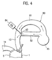
- the control apparatus of the present embodiment is featured in that it is provided with two sets of induction passages and it operates to select a desired one set of induction passages suitable for the fuel injection mode, as compared to the first embodiment in which the effective length of the intake manifold is changed in two stages. That is, the present embodiment employs, as an air flow changing system, an induction control system 80 shown in FIG. 4 instead of the system shown in FIG. 2. Both the embodiments have the same arrangement in other respects.
- the induction control system 80 is comprised of first induction pipes (one of which is denoted by reference numeral 81) for low engine speed, which correspond to the respective engine cylinders, and second induction pipes (one of which is shown by reference numeral 82) for high engine speed.
- the first and second pipes 81 and 82 constitute the intake manifold 21 (FIG. 1) of the engine 1.
- the first pipes 81 are connected at their upstream ends with a surge tank 85 in such a manner that the air supplied from the intake pipe 25 (FIG. 1) of the engine 1 to the surge tank 85 smoothly enters the first pipes 81.
- the first pipes 81 extend, while being smoothly curved, from the surge tank 85 along a circular arc having a large curvature.
- the first pipes 81 are connected at their downstream ends with the upstream ends of the intake ports 13 in such a manner that the air from the pipes 81 smoothly enters the intake ports 13.
- the second pipes 82 are communicated at their upstream ends with the upstream end portions of the first pipes 81, extend from the surge tank 85 along a straight line, and, at their downstream ends, open to the downstream end portions of the first pipes 81.
- the axes of the second pipes 82 are substantially perpendicular to the axes of the first pipes 81.
- the air receives a considerably large resistance both when it enters the second pipe 82 through the upstream open end of the pipe 82 and when it enters the first pipe 81 through the downstream open end of the pipe 82.
- the induction control system 80 further includes induction control valves 83 disposed at the downstream open ends of the second pipes 82 and each selectively taking either an open position shown by broken line in FIG. 4 or a closed position shown by solid line in FIG. 4, and solenoids 84 electrically connected with the output side of the ECU (stratified degree changing means) 70 and operable, under the control of the ECU 70, to open and close the induction control valves 83.
- the ECU 70 drives the solenoids 84 in accordance with the fuel injection mode or the engine operating state, whereby the induction control valves 83 are caused to be open and closed, thereby selecting the first pipes 81 or the second pipes 82.
- the air supplied from the intake pipe 25 to the surge tank 85 flows through the first pipes 81 to the intake ports 13, as shown by solid arrow in FIG. 4.
- the air flows smoothly through the first pipes 81 which makes the effective length of the induction passage defined in the system 80 long but extend while being smoothly curved. As a result, the formation of a tumble flow in the combustion chamber 5 is not hindered, and hence the stratified degree of intake air flow is enhanced.
- the induction control valves 83 are open, so that the communication between the first and second pipes 81 and 82 at the downstream ends of the second pipes 82 is allowed, the air flows through the first and second pipes 81 and 82 to the intake ports 13.
- the second pipes 82 shorten the effective length of the induction passage defined in the system 80, these pipes 82 are connected at their upstream and downstream ends with the surge tank 85 and the intake ports 13 (actually, connected with the first pipes 81) to form substantially right angles therebetween.
- the flow of the air is hindered, especially, at the communicating sections between the pipes 82 and the surge tank 85 and between the pipes 82 and the intake ports 13.
- the induction control valves 83 when the induction control valves 83 are open, their halves project into the first pipes 81, so that the air discharged from the second pipes 82 to the first pipes 81 generate a turbulent air flow and the air flowing from the first pipes 81 to the intake ports also generate a turbulent air flow.
- the flow of the air flowing through the pipes 81 and 82 to the intake ports 13 are hindered, resulting in a weak tumble flow in the combustion chamber and a degraded stratified degree of intake air flow.
- the selection of only the first pipes 81, which are long in length makes the air flow smooth as compared with the case where the second pipes 82 which are short in length are also selected, whereby a hindrance to the formation of tumble flow in the combustion chamber 5 can be eliminated.
- the ECU (stratified degree changing means) 70 drives the solenoids 84 of the induction control system 80 so as to cause the induction control valves 83 to close, whereby the air supply to the intake ports 13 through the first pipes 81 alone is selected.
- This makes it possible to enhance the formation of the tumble flow, to thereby enhance the stratified degree of the intake air flow in the combustion chamber 5, resulting in a stable combustion.
- the induction control valves 83 are closed under the control of the ECU 70, so that the air supply to the intake ports 13 is performed through the first and second pipes 81 and 82.
- an air flow changing system which constitutes part of the control apparatus of this invention may be of any type so long as it can vary the flow of air flowing through the induction system of an engine, thereby changing the stratified degree of the resultant intake air flow in the combustion chamber of the engine.
Description
- The present invention relates to an in-cylinder injection type internal combustion engine, and more particularly, to a control apparatus for an engine of this type which apparatus makes a stratified degree of the intake air flow generated in a combustion chamber suitable for a fuel injection mode, to thereby improve the fuel consumption and output of the engine.
- A spark-ignition type multi-cylinder internal combustion engine is provided with an induction system comprising an intake pipe in which a throttle valve is disposed and an intake manifold through which the intake air supplied from the intake pipe is distributed to respective cylinders of the engine. The vertical motions of pistons in the cylinders and the opening/closing actions of intake valves cause the air pressure in the induction system to periodically vary.
- If a positive pressure wave caused by the pressure pulsation reaches an intake valve which is open, the introduction of intake air into a cylinder through the intake valve is promoted. Thus, the pulsating intake air produces a supercharging effect. If a negative pressure wave, generated when the intake valve for a given cylinder was opened, reaches the intake valve of a different cylinder, the introduction of intake air into the latter cylinder is suppressed. That is, the induction interference between cylinders takes place. Moreover, the intake air acquires inertia while being transferred to a cylinder. The inertial induction produces a supercharging effect. The inertia of intake air increases with the increase in engine speed and in intake pipe length.
- In view of the above, the induction system is designed to improve the induction efficiency. In order to reduce the induction interference, a surge tank is provided between the intake pipe and the intake manifold. The induction system is configured to attain the supercharging effect of inertial induction and pulsating induction. However, an optimum length of the intake pipe for attainment of the supercharging effect varies depending on engine speed, whereas the intake pipe usually has a fixed length. Thus, it is difficult to attain the supercharging effect over the entire engine speed region.
- In this regard, various induction control systems for changing the intake pipe length depending on the engine operating state have been proposed. For example, an induction control system is known which changes the effective length of the intake manifold in two stages, by opening and closing an induction control valve to cause the effective-length increasing function of a detour induction passage, interposed between upstream portion and downstream portion of the intake manifold, to be selectively effective. This system closes the induction control valve to cause the intake air to flow from the upstream portion into the downstream portion of the intake manifold by way of the detour induction passage when the engine is in a low-speed region, and opens the valve to cause the air to bypass the detour passage so that the air flows directly into the downstream portion of the intake manifold. By changing the effective pipe length depending on the engine speed in this manner, the induction efficiency can be improved over the entire engine speed region.
- For spark-ignition type internal combustion engines, various in-cylinder injection type gasoline engines have been proposed which directly inject fuel into a combustion chamber, unlike conventional intake-manifold injection type engines. A typical in-cylinder injection type engine is arranged to inject fuel from a fuel injection valve into a cavity formed in the top of a piston of the engine when the engine is in a low-load region, to thereby form a substantially stoichiometric air-fuel mixture around an ignition plug at ignition timing and form a lean mixture around the substantially stoichiometric mixture. If such a stratified charging is achieved by performing the fuel injection in the compression-stroke injection mode (second-term injection mode), a lean air-fuel mixture whose air-fuel ratio is lean when observed over the entire of the cylinder is enabled to be burnt, the emission of harmful exhaust-gas components is reduced, and the fuel consumption is greatly improved. When the engine is in a medium- or high-load region, fuel is injected in the intake stroke to form a stoichiometric or rich mixture uniformly in the cylinder, thereby obtaining a desired engine output while preventing an overrich misfire.
- In order to stabilize the stratified charging for stable stratified combustion in the compression-stroke injection mode, some technical idea must be put into in designing the engine. For example, a technique of generating a circling flow (e.g., a so-called tumble flow or swirl flow) of intake air in a cavity formed in the top of a piston is proposed, whereby a substantially stoichiometric air-fuel mixture is retained in the cavity under the action of the circling flow of intake air.
- EP-A-661 432 relates to an internal combustion engine of the type in which the fuel is injected directly into a cylinder. EP-A-661 432 discloses a technical art in which, under a partial load, a pumping loss is reduced by a stratified combustion to enhance a fuel consumption, and during the maximum output operation, the output is increased by a premixture combustion, and the output of an engine is controlled, thereby enhancing the drivability, and in which, when the air/fuel ratio is changed over, the throttle valve opening or the amount of a valve lift is controlled so as to vary an amount of intake air, thereby preventing the output torque from being varied. Thus, the throttle valve opening is controlled so as to produce a proper turbulence in a cylinder.
- In order to further improve the fuel consumption and output of an in-cylinder injection type internal combustion engine, the present inventors attempted to utilize an induction control system. According to experiments, it was found that a stabilized combustion could not be achieved depending on a combination of fuel injection mode of the engine and an operating mode (effective intake pipe length) of the induction control system. For instance, in the case of using an induction control system provided with a detour induction passage which has a considerable length for the passage length adjustment and a complicated shape for avoiding interference with peripheral components, a stable combustion could not be attained, if the effective pipe length was made long at the time of engine operation in the compression-stroke injection mode. In the case of using a different type of induction control system which selects either a first induction passage which is long in length but small in change in the cross-sectional shape and a second induction passage which is short in length but large in change in the sectional shape, a stable combustion could not be attained if the effective pipe length made short by selecting the second passage.
- According to the knowledge of the present inventors, in order to obtain a stable combustion when the engine is operated in the compression-stroke injection mode, a strong circling flow of intake air must be generated to enhance a stratified degree of intake air flow, thereby increasing the degree of stratified charging. It is considered that the reason why the combustion cannot be stabilized resides in that the circling flow strong enough to attain a desired stratified degree of intake air flow cannot be generated. The strength of circling flow is represented, e.g., by a circling flow ratio (which is a ratio of the rotational speed of circling flow to the engine rotational speed). The strength of circling flow becomes greater as the circling flow ratio increases. Meanwhile, in the intake-stroke injection mode (first-term injection mode) selected when the engine is operated in a medium- or heavy load region, the circling flow enhances the uniformity of air-fuel mixture in the cylinder, but the strength of the circling flow does not greatly affect the stability of combustion.
- An object of the present invention is to provide a control apparatus for an in-cylinder injection type internal combustion engine, which apparatus can make the stratified degree of intake air flow suitable for the fuel injection mode, thereby improving the fuel consumption and output of the engine.
- According to the present invention, there is provided a control apparatus of an in-cylinder injection type internal combustion engine which is selectively operated in at least either a compression-stroke injection mode where fuel is injected in a compression stroke or an intake-stroke injection mode where the fuel is injected in an intake stroke of the engine.
- The control apparatus of this invention comprises an air flow changing system for introducing air into a combustion chamber of the engine and for changing a flow of the air, and stratified-degree changing means for operating the air flow changing system in accordance with the selected injection mode, to thereby change a stratified degree of an intake air flow which is generated by the air introduced into the combustion chamber. In the compression-stroke injection mode, the stratified-degree changing means operates the air flow changing system so as to enhance the stratified degree of the intake air flow.
- The present invention is advantageous in that the stratified degree of the intake air flow is made suitable for the fuel injection mode (engine operating state), to thereby attain a stable combustion in an in-cylinder injection type internal combustion engine, whereby the fuel consumption and output of the engine can be improved. Especially, the present invention makes it possible to change the flow of air in the induction system so as to enhance the stratified degree of the intake air flow when the engine is operated in the compression-stroke injection mode in which a combustion is liable to be affected by the stratified degree of the intake air flow. As a consequence, the stratified charging can be stabilized for stable stratified combustion.
- In the present invention, preferably, the air flow changing system has an induction passage through which the air flows, and operates to change an effective length of the induction passage. More preferably, when the internal combustion engine is operated in the compression-stroke injection mode, the stratified-degree changing means causes the air flow changing system to operate to shorten or lengthen the effective length of the induction passage, thereby enhancing the stratified degree of the intake air flow.
- With these preferred arrangements, the induction passage length can be changed to an optimum length suitable for the injection mode, to thereby attain a desired stratified degree of the intake air flow suited to the injection mode. Especially, in the case of using an air flow changing system designed to permit the air to smoothly flow therethrough when the length of the induction passage defined therein is made long, the induction passage length can be lengthened when the engine is operated in the compression-stroke injection mode. Conversely, the induction passage length can be shortened in case that an air flow changing system is employed which is designed to establish a smooth air flow in a condition that the induction passage is short in length. In either case, the stratified degree of the intake air flow in the compression-stroke injection mode is enhanced, to thereby attain a stable combustion and an improved fuel efficiency. Additionally, in the case of making the length of the induction passage long in the compression-stroke injection mode, the volumetric efficiency can be improved in the compression-stroke injection mode, whereby the engine output and combustion stability can be further enhanced.
-
- FIG. 1 is a schematic view of an in-cylinder injection type internal combustion engine equipped with a control apparatus according to a first embodiment of the present invention;
- FIG. 2 is a schematic view showing an induction control system for use as an air flow changing system in the control apparatus of the first embodiment;
- FIG. 3 is a map with which a fuel injection control of the engine shown in FIG. 1 is carried out; and
- FIG. 4 is a schematic view showing an induction control system which serves as an air flow changing system of a control apparatus according to a second embodiment of the present invention.
-
- A spark-ignition, in-cylinder injection type internal combustion engine (hereinafter referred to as engine) on which a control apparatus according to a first embodiment of this invention is mounted will be explained.
- Referring to FIG. 1, the engine 1 has a
cylinder head 2 thereof fitted with a spark plug 3 and an electromagnetic fuel injection valve 4 for each cylinder, so that fuel may be injected from the fuel injection valve 4 directly into a combustion chamber 5 concerned. Ahemispherical cavity 8 is formed in the top surface of a piston 7 disposed in the cylinder 6 for reciprocal motion. The cavity is located at a position to which fuel spray can reach if the fuel is injected from the fuel injection valve 4 at timing in a latter stage of the compression stroke of the engine. The theoretical compression ratio of the engine 1 is set to a value (in this embodiment, approximately 12) higher than that of an intake-manifold injection type engine. A DOHC four-valve system is employed as a valve driving mechanism. Intake-side and exhaust-side camshafts 11 and 12 for driving intake andexhaust valves 9 and 10 are rotatably held at an upper portion of thecylinder head 2. - The
cylinder head 2 is formed withintake ports 13 which extend substantially upright between thecamshafts 11 and 12. Intake air flow having passed through theintake port 13 can generate a tumble flow in the combustion chamber 5.Exhaust ports 14 extend substantially in the horizontal direction, as in the case of those of ordinary engines. A large-diameter EGR port 15 diverges diagonally downward from the exhaust port concerned. The engine 1 is provided with awater temperature sensor 16 for detecting a cooling water temperature Tw, acrank angle sensor 17 for outputting a crank angle signal SGT at predetermined crank positions for each cylinder and for detecting the engine rotational speed Ne based on the crank angle signal SGT. Further, anignition coil 19 for supplying a high voltage to the spark plug 3 is provided. One of the camshafts, which rotate at half the speed of the crankshaft, is fitted with a cylinder discriminating sensor (not shown) for outputting a cylinder discriminating signal SGC, whereby the cylinder for which the crank angle signal SGT is output is discriminated based on the sensor signal SGC. - The
intake ports 13 are connected, through anintake manifold 21, with anintake pipe 25 which is provided with a throttle body 23, a first air bypass valve (#1ABV) 24 of a stepper-motor type serving as intake-air amount correction means, and anair cleaner 22. Theintake pipe 25 is further provided with a large-diameterair bypass pipe 26 through which intake air is introduced, bypassing the throttle body 23, to theintake manifold 21 and in which a second air bypass valve (#2ABV) 27 of a large linear-solenoid type is disposed. Theair bypass pipe 26 has a flow area substantially equal to that of theintake pipe 25, so that a quantity of intake air, required for engine operation in a low or medium speed region, can flow through thepipe 26 when the secondair bypass valve 27 is fully open. The firstair bypass valve 24 has a flow area smaller than that of the secondair bypass valve 27 and is used to finely adjust the intake air amount. - The throttle body 23 is provided with a butterfly type throttle valve 28 for opening and closing the intake passage formed therein, a
throttle position sensor 29 for detecting the throttle opening degree th, and anidle switch 30 for detecting a fully-closed state of the throttle valve 28, i.e., an idle state of the engine. An intake air temperature sensor and an atmospheric pressure sensor (none of which is shown), for determining the density of intake air are disposed in theair cleaner 22. These sensors deliver output signals indicative of the atmospheric pressure and the intake air temperature, respectively. In the vicinity of the inlet of theintake pipe 25, a Karman's vortex typeair flow sensor 32 is disposed and outputs a vortex occurrence signal which is proportional to the volumetric air flow rate Qa per intake stroke. Instead of theair flow sensor 32, a boost pressure sensor, not shown, for detecting the intake air pressure within theintake pipe 25 may be provided. - The engine 1 is provided with a control apparatus which operates to make a stratified degree of intake air flow, generated by air introduced into the combustion chamber, suitable for the fuel injection mode. The control apparatus includes an air flow changing system for changing the flow of the air in the induction system of the engine 1, and stratified-degree changing means for operating the air flow changing system in accordance with the injection mode to thereby change the stratified degree of the intake air flow. In this embodiment, the stratified degree changing means is constituted by the below-mentioned electronic control unit (ECU) 70, and the air flow changing system is constituted by an
induction control system 18 which is of an effective pipe length changing type. - Referring to FIG. 2, the
induction control system 18 includes afirst induction pipe 18a which constitutes a downstream portion of theintake pipe 25. A downstream end portion of thefirst pipe 18a constitutes a surge tank. Thefirst pipe 18a has a downstream end thereof connected with upstream ends of second induction pipes (detour pipes). One of the second pipes is denoted byreference numeral 18b. Sections where thepipes first pipe 18a is connected with upstream ends of third induction pipes which cooperate with thesecond pipes 18b to constitute theintake manifold 21 whose effective length is variable. One of the third pipes is shown byreference numeral 18c. Induction control valves (one of which is shown byreference numeral 18d) for selectively permitting or prohibiting the communication between thefirst pipe 18a and thethird pipes 18c are disposed at the second communication sections. At third communicating sections adjacent to the second communicating sections, the downstream ends of thesecond pipes 18b are connected to the upstream ends of thethird pipes 18c whose downstream ends are connected to the upstream ends of theintake ports 13 for the respective cylinders of the engine 1. - The
pipes induction control system 18 are disposed so as not to interfere with various components disposed in the engine room of a vehicle on which the engine 1 is installed and with the bonnet hood of the vehicle. In addition to such a general requirement, thesecond pipes 18b must satisfy additional requirements such that they must be formed into a shape which permits their upstream and downstream ends to be connected with the downstream ends of thethird pipes 18c and their lengths are long enough to exhibit the function of increasing the effective length of theintake manifold 21. As a consequence, each of thesecond pipes 18b has a considerable length, has a bent or curved shape as viewed in the lengthwise direction of thepipe 18b, and has a cross section which varies in shape at different lengthwise positions of thepipe 18b. Thus, the air receives a large resistance when it flows through thepipe 18b. - Especially, in a V-type engine having a so-called vertical intake port, there is a limited space between the upper portion of the engine and the bonnet hood, so that the induction control system is disposed between the right and left cylinder banks of the engine. In this case, the
second pipe 18b must be formed into a further complicated shape where the cross-sectional area of the pipe greatly varies along its lengthwise direction. Meanwhile, the first andthird pipes - The
induction control valve 18d, disposed at the second communicating section where thepipes movable rod 33a of asolenoid 33 through a coupling member such as a lever, not shown. Thesolenoid 33 includes an excitation coil electrically connected with the output side of an electric control unit (ECU) 70. Theinduction control valve 18d takes an ON position (shown by broken line in FIG. 2) where it permits the communication between thepipes solenoid 33 is energized, and takes an OFF position (shown by solid line in FIG. 2) where it prohibits the communication therebetween when the excitation coil is de-energized, for instance. - When the
induction control valve 18d is in the OFF position, thefirst pipe 18a is connected through thesecond pipe 18b with thethird pipe 18c, so that the length of the intake manifold 21 (more generally, the length of the intake passage of the induction system) becomes long. The air supplied from theintake pipe 25 flows along the induction route constituted by thepipes induction control system 18 is unsmoothed by a degree corresponding to the induction resistance of thesecond pipe 18b, so that the strength of the tumble air flow formed in the combustion chamber 5 is weakened. On the other hand, when theinduction control valve 18d is at the ON position, thesecond pipe 18b is short-circuited, so that thefirst pipe 18a is connected directly with thethird pipe 18c. As a consequence, the length of theintake manifold 21 is shortened, and a bend in the resultant induction passage defined in theintake manifold 21 is relatively lessened and hence a change in the cross-sectional area of this passage is relatively small. The intake air flows along the route comprised of the first andthird pipes induction control system 18 is smoothed by a degree corresponding to the eliminated induction resistance of thesecond pipe 18b, so that the resultant tumble flow is strengthened. - The
Exhaust ports 14 are connected, through anexhaust manifold 41 provided with an O2 sensor 40, to anexhaust pipe 43 which is provided with a threeway catalyst 42, a muffler (not shown) and the like. Theaforementioned EGR ports 15 are connected to the downstream of the throttle valve 28 and the upstream of theintake manifold 21 through a large-diameter EGR pipe 44 in which a stepper-motortype EGR valve 45 is provided. - The fuel stored in a
fuel tank 50 is sucked up by a motor-operated low-pressure fuel pump 51, and is supplied to the engine 1 through a low-pressure feed pipe 52. The pressure of the fuel in the low-pressure feed pipe 52 is adjusted to a relatively low pressure by a firstfuel pressure regulator 54 interposed in the line of areturn pipe 53. The fuel supplied toward the engine 1 is fed into each fuel injection valve 4 through a high-pressure feed pipe 56 and adelivery pipe 57 by means of a high-pressure fuel pump 55 attached to thecylinder head 2. Thefuel pump 55 is driven by thecamshaft 11 or 12 to generate a discharge pressure equal to or greater than 5Ma to 7Ma even when the engine 1 runs idle. The fuel pressure in thedelivery pipe 57 is adjusted to a relatively high pressure by a secondfuel pressure regulator 59 interposed in the line of areturn pipe 58. A fuelpressure selector valve 60, attached to the secondfuel pressure regulator 59, operates at its ON position to relieve the fuel, thereby lowering the fuel pressure in thedelivery pipe 57. Part of fuel used to lubricate and cool the high-pressure fuel pump 55 is returned to thefuel tank 50 through areturn pipe 61. - An electronic control unit (ECU) 70 provided in a passenger cabin of the vehicle includes an I/O unit, storage units (ROM, RAM, BURAM, etc.) used to store control program, control map and the like, central processing unit (CPU), timer counter, and the like. The
ECU 70 conducts an overall control of the engine 1. - Various switches (not shown) for detecting the operating states of an air conditioner, power steering device, automatic transmission and the like which apply loads to the engine 1 when operated are connected to the input side of the
ECU 70 which receives detection signals from these switches. In addition to the above-mentioned various sensors and switches, many switches and sensors (not shown) are connected to the input side of theECU 70 the output side of which is connected to warning lights, pieces of equipment and the like. - In accordance with input signals supplied from the sensors and switches concerned, the
ECU 70 determines fuel injection mode, fuel injection amount, fuel-injection termination timing, ignition timing, EGR gas introduction amount and the like, and then controls the fuel injection valves 4, theignition coil 19, theEGR valve 45 and the like. - In the following, a brief explanation will be given as to an ordinary control of the engine 1.
- When the driver turns the ignition key switch to an ON position, the
ECU 70 turns the low-pressure fuel pump 51 and the fuelpressure switching valve 60 on, thereby supplying the fuel injection valves 4 with the fuel at low pressure since the high-pressure fuel pump 55 insufficiently operates at the time of cranking the engine 1. - When the driver turns the ignition key switch to a START position, the engine 1 is cranked by a self-starter, not shown, and at the same time the
ECU 70 starts a fuel injection control. At this time, theECU 70 selects the intake-stroke injection mode (first-term injection mode), and controls fuel injection to attain a relatively rich air-fuel ratio. The reason for doing this is that a fuel injection amount must be increased to ensure a sufficient amount of fuel which contributes to combustion since the rate of vaporization of fuel is low when the engine is in a cold state. Further, theECU 70 closes the secondair bypass valve 27 at the start of the engine, so that intake air is supplied into the combustion chamber 5 through the clearance between the throttle valve 28 and the peripheral wall of theintake pipe 25 and through the bypass passage where the firstair bypass valve 24 is disposed. - When the engine 1 starts an idle operation after the engine starting is completed, the high-
pressure fuel pump 55 initiates a rated discharge operation. In response to this, theECU 70 turns off the fuelpressure selector valve 60, and supplies the fuel at high fuel pressure to the fuel injection valves 4. Until the engine cooling water temperature Tw is raised to a predetermined value, theECU 70 selects the intake-stroke injection mode for fuel injection to secure a rich air-fuel ratio, and closes the secondair bypass valve 27, just as at the time of the engine starting. The idle speed control that is based on the variation of the loads of auxiliary apparatuses, such as an air conditioner, is carried out by means of the firstair bypass valve 24, as in the case of the manifold-injection type engine. When the activation of the O2 sensor 40 is completed, theECU 70 starts air-fuel ratio feedback control in accordance with the output voltage of the O2 sensor 40, and the three-way catalyst 42 is permitted to remove harmful exhaust gas components. As described in the above, when the engine is cold, fuel injection control is effected substantially in the same manner as in the case of the manifold-injection engine. Control response and control accuracy are improved in the in-cylinder injection engine which is free from adherence of fuel drop to the wall of theintake manifold 21. - When warming up the engine 1 is finished, the
ECU 70 retrieves a present fuel injection control region from a fuel injection control map shown in FIG. 3 in accordance with the engine speed Ne and a target average effective pressure Pe which is obtained from the intake air amount Qa or throttle opening th, etc. Then, theECU 70 determines the fuel injection mode, fuel injection quantity, and fuel injection timing, and drives the fuel injection valves 4. Further, theECU 70 controls the open-close operation of the first and secondair bypass valves EGR valves 45. - In a low-load, low-speed operating region for idle operation, etc., the engine is operated in a compression-stroke lean injection region (the second-term injection region), as shown in the map of FIG. 3, so that the
ECU 70 selects a compression-stroke injection mode (second-term injection mode). The secondair bypass valve 27 and theEGR valve 45 are opened, and the fuel is injected so as to obtain a lean average air-fuel ratio (e.g., about 30 to 40). - The intake air introduced into the combustion chamber through the
intake port 13 generates a tumble flow, so that a fuel spray is kept in thecavity 8 of the piston 7 under the action of the tumble flow. As a result, an air-fuel mixture of an air-fuel ratio near the stoichiometric air-fuel ratio is formed in a layer around the spark plug 3 at the time of ignition, so that the fuel can catch fire even with a lean overall air-fuel ratio, whereby the emission of CO and HC can be reduced. The fuel consumption is largely improved in cooperation with the reduction of pumping loss. The idle speed control responsive to variations in the engine load caused by operations of the auxiliary apparatuses is carried out by increasing or decreasing the fuel injection quantity, so that control response is also very high. In this control region, theECU 70 opens theEGR valve 45 to introduce a large amount (e.g., 30% or more) of EGR gas into the combustion chamber 5, thereby greatly reducing the emission of NOx. - In a medium-load region for constant-speed drive or the like, the engine is operated in an intake-stroke lean injection region (first-term injection region), a stoichiometric air-fuel ratio feedback region (stoichio-feedback region) or open-loop region shown in FIG. 3, depending on the engine load state and the engine speed Ne, so that the
ECU 70 selects an intake-stroke injection mode (first-term injection mode), and injects the fuel so as to obtain a predetermined air-fuel ratio suitable for the respective region. More specifically, the respective opening degrees of the first and secondair bypass valves EGR valve 45 kept closed. In the stoichio-feedback region, the air-fuel ratio feedback control is carried out in accordance with the output voltage of the O2 sensor 40, with the opening degrees of the secondair bypass valve 27 and theEGR valve 45 controlled by theECU 70. - In the intake-stroke lean region, the fuel can be ignited even with a lean air-fuel ratio, due to the effect of a turbulence attributable to the tumble flow that is formed by the intake air flow introduced through the
intake port 13. In the stoichio-feedback region, harmful exhaust-gas components are removed by the three-way catalyst 42. By controlling theEGR valve 45 so as to introduce a suitable amount of EGR gas into the combustion chamber 5, the emission of NOx can be reduced. - In a high-load region for sudden acceleration or high-speed drive, an open-loop region shown in FIG. 3 is reached, so that the
ECU 70 selects the intake-stroke injection mode (enrich mode), closes the secondair bypass valve 27, and injects the fuel so as to obtain a relatively rich air-fuel ratio (which is fuel-richer than the stoichiometric air-fuel ratio) in accordance with the intake air amount Qa or throttle opening th, engine speed Ne, etc. Since a fuel-cut region shown in FIG. 3 is reached when the vehicle is coasting in a medium- or high-speed drive, theECU 70 stops the fuel injection, whereby the fuel consumption is improved and the emission of harmful exhaust-gas components is reduced. Fuel-cut operation is terminated immediately when the engine speed Ne falls below a restoration speed for restarting the fuel supply or when the accelerator pedal is depressed. - With reference to FIG. 2, a control of the effective length of the
intake manifold 21 will be explained which control is performed by theinduction control system 18 and the ECU 70 (stratified degree changing means) in order to control the stratified degree of intake air flow. - In the
induction control system 18 shown in FIG. 2, a low-speed induction port having a long effective length and adaptable for low engine speed is constituted by theinduction passages induction control valve 18d is open, whereas a high-speed induction having a short effective length and adaptable for high engine speed is constituted by theinduction passages induction passage 18b as compared to those of the high-speed induction port. The low-speed induction port weakens the strength (the stratified degree of intake air flow) of tumble flow generated by the intake air supplied to the combustion chamber 5 through this port, whereas the high-speed induction port strengthens the tumble flow of intake air supplied therethrough. In this manner, the tumble flow of intake air has its strength which varies depending on the effective length of the intake manifold 21 (the induction passage defined in the induction control system 18). The strength of the tumble flow affects a combustion state in the in-cylinder injection engine. Especially, the stratified degree of intake air flow must be enhanced in the compression-stroke injection mode where an unstable combustion is liable to occur if the tumble flow is weakened or if the stratified degree of intake air flow decreases. - In the present embodiment, the
induction control valve 18d is open/close-controlled by theECU 70 in accordance with the fuel injection mode selected based on the map shown in FIG. 3, to make the effective length of the induction passage adaptable for the selected fuel injection mode, to thereby attain the tumble flow having a desired strength (intake air flow having a desired stratified degree) suitable for the fuel injection mode. As mentioned later, in the enrich injection mode, the induction control valve is controlled in a different manner between when the engine is in a low-speed zone and when it is in a high-speed zone of the open-loop region. - More specifically, the open/close control of the
induction control valve 18 in the respective fuel injection modes is carried out as follows: - When the engine 1 is in a low engine-speed zone of the open-loop region (a low-speed and high-load operating region), i.e., when the engine is operated in the intake-stroke enrich-injection mode, the
induction control valve 18d is caused to close, thereby increasing the effective length of the intake manifold 21 (the induction passage defined in the induction control system 18) to constitute the induction port adaptable for low engine speed. As a result, the supercharging effect of inertial induction is enhanced to improve the induction efficiency, resulting in an increased engine output torque. - When the engine 1 is operated in operating regions other than the low engine-speed zone of the open-loop region, the
induction control valve 18d is caused to be open, thereby decreasing the effective length of theintake manifold 21 to constitute the induction port adaptable for high engine speed. As a consequence, the engine 1 and theinduction control system 18 functions as follows: - At the time of engine operation in the compression-stroke injection mode, the
induction control valve 18d is caused to open to shorten the effective length of theintake manifold 21. The air supplied from theintake pipe 25 into the shortenedintake manifold 21 is smoothly sucked into the combustion chamber 5, thereby generating a strong tumble flow of air in thecavity 8 which is formed at the top of the piston 7. That is, the stratified degree of intake air flow is enhanced. The fuel injected at the timing in a latter stage of compression stroke is positively retained within thecavity 8 under the action of the strong tumble flow. As a result, a considerably rich air-fuel mixture is formed stably around the ignition plug 3 at the ignition timing. This makes it possible to stabilize a combustion of fuel, resulting in reduced emission of harmful exhaust-gas components and improved fuel consumption. - At the time of engine operation in the intake-stroke lean injection mode, the
induction control valve 18d is caused to open, and hence an amount of intake air sucked into the combustion chamber 5 increases. As a consequence, the fuel injected into the combustion chamber 5 is permitted to be rapidly burnt, resulting in a stable combustion of uniform lean air-fuel mixture. - At the time of engine operation in the intake-stroke stoichio-injection mode, the
induction control valve 18d is caused to open, and hence the combustion speed increases. Thus, the antiknock property is improved. This makes it possible to advance the ignition timing, thereby improving the fuel efficiency. - In case that the engine 1 is in a high-speed side zone of the open-loop region and is hence operated in the intake-stroke enrich injection mode, the
induction control valve 18d is caused to be open, whereby the induction efficiency is improved and the engine torque increases. - In the following, a control apparatus according to a second embodiment of the present invention will be explained.
- The control apparatus of the present embodiment is featured in that it is provided with two sets of induction passages and it operates to select a desired one set of induction passages suitable for the fuel injection mode, as compared to the first embodiment in which the effective length of the intake manifold is changed in two stages. That is, the present embodiment employs, as an air flow changing system, an
induction control system 80 shown in FIG. 4 instead of the system shown in FIG. 2. Both the embodiments have the same arrangement in other respects. - Referring to FIG. 4, the
induction control system 80 is comprised of first induction pipes (one of which is denoted by reference numeral 81) for low engine speed, which correspond to the respective engine cylinders, and second induction pipes (one of which is shown by reference numeral 82) for high engine speed. The first andsecond pipes - The
first pipes 81 are connected at their upstream ends with asurge tank 85 in such a manner that the air supplied from the intake pipe 25 (FIG. 1) of the engine 1 to thesurge tank 85 smoothly enters thefirst pipes 81. Thefirst pipes 81 extend, while being smoothly curved, from thesurge tank 85 along a circular arc having a large curvature. Thefirst pipes 81 are connected at their downstream ends with the upstream ends of theintake ports 13 in such a manner that the air from thepipes 81 smoothly enters theintake ports 13. - The
second pipes 82 are communicated at their upstream ends with the upstream end portions of thefirst pipes 81, extend from thesurge tank 85 along a straight line, and, at their downstream ends, open to the downstream end portions of thefirst pipes 81. At the upstream and downstream ends, the axes of thesecond pipes 82 are substantially perpendicular to the axes of thefirst pipes 81. Thus, the air receives a considerably large resistance both when it enters thesecond pipe 82 through the upstream open end of thepipe 82 and when it enters thefirst pipe 81 through the downstream open end of thepipe 82. - The
induction control system 80 further includesinduction control valves 83 disposed at the downstream open ends of thesecond pipes 82 and each selectively taking either an open position shown by broken line in FIG. 4 or a closed position shown by solid line in FIG. 4, andsolenoids 84 electrically connected with the output side of the ECU (stratified degree changing means) 70 and operable, under the control of theECU 70, to open and close theinduction control valves 83. TheECU 70 drives thesolenoids 84 in accordance with the fuel injection mode or the engine operating state, whereby theinduction control valves 83 are caused to be open and closed, thereby selecting thefirst pipes 81 or thesecond pipes 82. - When the
induction control valves 83 are closed so that the communication between thefirst pipes 81 and thesecond pipes 82 at the downstream ends of thesecond pipes 82 is prohibited, the air supplied from theintake pipe 25 to thesurge tank 85 flows through thefirst pipes 81 to theintake ports 13, as shown by solid arrow in FIG. 4. The air flows smoothly through thefirst pipes 81 which makes the effective length of the induction passage defined in thesystem 80 long but extend while being smoothly curved. As a result, the formation of a tumble flow in the combustion chamber 5 is not hindered, and hence the stratified degree of intake air flow is enhanced. - On the other hand, when the
induction control valves 83 are open, so that the communication between the first andsecond pipes second pipes 82 is allowed, the air flows through the first andsecond pipes intake ports 13. Although thesecond pipes 82 shorten the effective length of the induction passage defined in thesystem 80, thesepipes 82 are connected at their upstream and downstream ends with thesurge tank 85 and the intake ports 13 (actually, connected with the first pipes 81) to form substantially right angles therebetween. Thus, the flow of the air is hindered, especially, at the communicating sections between thepipes 82 and thesurge tank 85 and between thepipes 82 and theintake ports 13. Moreover, when theinduction control valves 83 are open, their halves project into thefirst pipes 81, so that the air discharged from thesecond pipes 82 to thefirst pipes 81 generate a turbulent air flow and the air flowing from thefirst pipes 81 to the intake ports also generate a turbulent air flow. As a consequence, the flow of the air flowing through thepipes intake ports 13 are hindered, resulting in a weak tumble flow in the combustion chamber and a degraded stratified degree of intake air flow. - As explained in the above, in the
induction control system 80, the selection of only thefirst pipes 81, which are long in length, makes the air flow smooth as compared with the case where thesecond pipes 82 which are short in length are also selected, whereby a hindrance to the formation of tumble flow in the combustion chamber 5 can be eliminated. - At least when the engine 1 is operated in the compression-stroke injection mode, therefore, the ECU (stratified degree changing means) 70 drives the
solenoids 84 of theinduction control system 80 so as to cause theinduction control valves 83 to close, whereby the air supply to theintake ports 13 through thefirst pipes 81 alone is selected. This makes it possible to enhance the formation of the tumble flow, to thereby enhance the stratified degree of the intake air flow in the combustion chamber 5, resulting in a stable combustion. On the other hand, when the engine operates in the fuel injection mode other than, e.g., the compression-stroke injection mode, theinduction control valves 83 are closed under the control of theECU 70, so that the air supply to theintake ports 13 is performed through the first andsecond pipes - The present invention is not limited to the first and second embodiments, but may be modified in various manners. For example, an air flow changing system which constitutes part of the control apparatus of this invention may be of any type so long as it can vary the flow of air flowing through the induction system of an engine, thereby changing the stratified degree of the resultant intake air flow in the combustion chamber of the engine.
- Where technical features mentioned in any claim are followed by reference signs, those reference signs have been included for the sole purpose of increasing the intelligibility of the claims and accordingly, such reference signs do not have any limiting effect on the scope of each element identified by way of example by such reference signs.
Claims (3)
- A control apparatus of an in-cylinder injection type internal combustion engine which is selectively operated in at least either a compression-stroke injection mode where fuel is injected in a compression stroke or an intake-stroke injection mode where the fuel is injected in an intake stroke of the engine, the control apparatus comprising:wherein the air flow changing system (18; 80) has an induction passage (18a, 18b, 18c; 81, 82) through which the air flows, and operates to change an effective length of the induction passage (18a, 18b, 18c; 81, 82).an air flow changing system (18; 80) for introducing air into a combustion chamber (5) of the engine (1) and for changing a flow of the air; andstratified-degree changing means (70) for operating the air flow changing system (18; 80) in accordance with the selected injection mode, to thereby change a stratified degree of an intake air flow which is generated by the air introduced into the combustion chamber, the stratified-degree changing means (70) operating the air flow changing system (18; 80), in the compression-stroke injection mode, so as to enhance the stratified degree of the intake air flow;
- The control apparatus according to claim 1, wherein the stratified-degree changing means (70) causes the air flow changing system (80) to operate to shorten the effective length of the induction passage (18a, 18b, 18c), thereby enhancing the stratified degree of the intake air flow, when the internal combustion engine (1) is operated in the compression-stroke injection mode.
- The control apparatus according to claim 1, wherein the stratified-degree changing means (70) causes the air flow changing system (80) to operate to lengthen the effective length of the induction passage (81, 82), thereby enhancing the stratified degree of the intake air flow, when the internal combustion engine (1) is operated in the compression-stroke injection mode.
Applications Claiming Priority (3)
| Application Number | Priority Date | Filing Date | Title |
|---|---|---|---|
| JP334156/96 | 1996-12-13 | ||
| JP33415696A JP3250475B2 (en) | 1996-12-13 | 1996-12-13 | Control device for in-cylinder injection type internal combustion engine |
| JP33415696 | 1996-12-13 |
Publications (3)
| Publication Number | Publication Date |
|---|---|
| EP0848146A2 EP0848146A2 (en) | 1998-06-17 |
| EP0848146A3 EP0848146A3 (en) | 1999-05-06 |
| EP0848146B1 true EP0848146B1 (en) | 2003-04-02 |
Family
ID=18274170
Family Applications (1)
| Application Number | Title | Priority Date | Filing Date |
|---|---|---|---|
| EP97121748A Expired - Lifetime EP0848146B1 (en) | 1996-12-13 | 1997-12-10 | Control apparatus for an in-cylinder injection type internal combustion engine |
Country Status (6)
| Country | Link |
|---|---|
| US (1) | US5937821A (en) |
| EP (1) | EP0848146B1 (en) |
| JP (1) | JP3250475B2 (en) |
| KR (1) | KR100237534B1 (en) |
| CN (1) | CN1090282C (en) |
| DE (1) | DE69720384T2 (en) |
Families Citing this family (28)
| Publication number | Priority date | Publication date | Assignee | Title |
|---|---|---|---|---|
| DE19727385C2 (en) | 1997-06-27 | 2002-10-10 | Bosch Gmbh Robert | System for operating an internal combustion engine with direct injection, in particular a motor vehicle |
| US6481425B1 (en) * | 1999-10-12 | 2002-11-19 | Siemens Vdo Automotive Inc. | Air quantity control for smooth switching in gasoline direct injection engine |
| US7210444B2 (en) * | 2002-05-17 | 2007-05-01 | Brp-Rotax Gmbh & Co. Kg | Variable air intake pipe length |
| DE10246182B3 (en) * | 2002-10-02 | 2004-03-04 | Meta Motoren- Und Energie-Technik Gmbh | Auxiliary control valve for intake channel of reciprocating piston engine has flow body defining annular flow channel and cooperating valve element displaced from central position by opening and closure magnets |
| JP4696946B2 (en) * | 2006-02-14 | 2011-06-08 | マツダ株式会社 | Engine intake control device |
| EP2018471B8 (en) * | 2006-05-09 | 2011-03-30 | Toyota Jidosha Kabushiki Kaisha | Intake control device for internal combustion engine |
| DE102006035096B4 (en) * | 2006-07-28 | 2014-07-03 | Continental Automotive Gmbh | Method and device for operating an internal combustion engine |
| DE102008052387A1 (en) * | 2007-11-01 | 2009-06-04 | Mitsubishi Fuso Truck and Bus Corp., Kawasaki | Combustion control system of a diesel engine |
| JP5271159B2 (en) * | 2009-06-08 | 2013-08-21 | 本田技研工業株式会社 | Control device for internal combustion engine |
| JP5707967B2 (en) * | 2011-01-24 | 2015-04-30 | 日産自動車株式会社 | Supercharging pressure diagnosis device for internal combustion engine |
| US9605629B2 (en) | 2014-02-14 | 2017-03-28 | Cnh Industrial America Llc | Under-hood mounting configuration for a control unit of a work vehicle |
| CN107435593B (en) * | 2016-05-26 | 2019-11-01 | 长城汽车股份有限公司 | Engine pack and vehicle with it |
| US11041456B2 (en) | 2017-03-30 | 2021-06-22 | Quest Engines, LLC | Internal combustion engine |
| US10590834B2 (en) | 2017-03-30 | 2020-03-17 | Quest Engines, LLC | Internal combustion engine |
| US10598285B2 (en) | 2017-03-30 | 2020-03-24 | Quest Engines, LLC | Piston sealing system |
| US10989138B2 (en) | 2017-03-30 | 2021-04-27 | Quest Engines, LLC | Internal combustion engine |
| US10526953B2 (en) | 2017-03-30 | 2020-01-07 | Quest Engines, LLC | Internal combustion engine |
| US10753308B2 (en) | 2017-03-30 | 2020-08-25 | Quest Engines, LLC | Internal combustion engine |
| US10590813B2 (en) | 2017-03-30 | 2020-03-17 | Quest Engines, LLC | Internal combustion engine |
| US10465629B2 (en) | 2017-03-30 | 2019-11-05 | Quest Engines, LLC | Internal combustion engine having piston with deflector channels and complementary cylinder head |
| JP6894981B2 (en) | 2017-04-28 | 2021-06-30 | クエスト エンジンズ,エルエルシー | Variable volume chamber device |
| US10883498B2 (en) | 2017-05-04 | 2021-01-05 | Quest Engines, LLC | Variable volume chamber for interaction with a fluid |
| US10711708B2 (en) * | 2017-08-25 | 2020-07-14 | Mazda Motor Corporation | Control device for engine |
| JP6642539B2 (en) * | 2017-08-25 | 2020-02-05 | マツダ株式会社 | Control device for compression ignition engine |
| US11060636B2 (en) | 2017-09-29 | 2021-07-13 | Quest Engines, LLC | Engines and pumps with motionless one-way valve |
| US11134335B2 (en) | 2018-01-26 | 2021-09-28 | Quest Engines, LLC | Audio source waveguide |
| US10753267B2 (en) | 2018-01-26 | 2020-08-25 | Quest Engines, LLC | Method and apparatus for producing stratified streams |
| CN111520245B (en) * | 2020-03-20 | 2022-08-30 | 浙江吉利汽车研究院有限公司 | Engine combustion control method and system |
Family Cites Families (10)
| Publication number | Priority date | Publication date | Assignee | Title |
|---|---|---|---|---|
| JP2534630B2 (en) * | 1986-04-28 | 1996-09-18 | マツダ株式会社 | Engine intake system |
| GB2221954B (en) * | 1988-08-16 | 1992-07-08 | Austin Rover Group | An internal combustion engine inlet manifold |
| JPH03281915A (en) * | 1990-03-29 | 1991-12-12 | Mazda Motor Corp | Multiple suction valve type engine |
| JPH05113146A (en) * | 1991-10-23 | 1993-05-07 | Toyota Motor Corp | Internal combustion engine |
| DE4333053A1 (en) * | 1993-09-29 | 1995-03-30 | Opel Adam Ag | Internal combustion engine with an air intake system |
| DE69416502T2 (en) * | 1993-12-28 | 1999-06-24 | Hitachi Ltd | Method and device for controlling an internal combustion engine |
| US5709190A (en) * | 1995-04-27 | 1998-01-20 | Yamaha Hatsudoki Kabushiki Kaisha | Combustion chamber and induction system for engine |
| JP3087309B2 (en) * | 1995-05-16 | 2000-09-11 | 三菱自動車工業株式会社 | In-cylinder internal combustion engine |
| FR2735528B1 (en) * | 1995-06-19 | 1997-07-25 | Inst Francais Du Petrole | METHOD AND DEVICE FOR CONTROLLING THE AIR TO THE INTAKE OF A CONTROLLED IGNITION 4-STROKE ENGINE |
| JP3478318B2 (en) * | 1996-08-27 | 2003-12-15 | 三菱自動車工業株式会社 | Control device for in-cylinder injection spark ignition internal combustion engine |
-
1996
- 1996-12-13 JP JP33415696A patent/JP3250475B2/en not_active Expired - Fee Related
-
1997
- 1997-12-10 EP EP97121748A patent/EP0848146B1/en not_active Expired - Lifetime
- 1997-12-10 DE DE69720384T patent/DE69720384T2/en not_active Expired - Lifetime
- 1997-12-12 CN CN97114184A patent/CN1090282C/en not_active Expired - Fee Related
- 1997-12-12 US US08/990,144 patent/US5937821A/en not_active Expired - Fee Related
- 1997-12-13 KR KR1019970068419A patent/KR100237534B1/en not_active IP Right Cessation
Also Published As
| Publication number | Publication date |
|---|---|
| JPH10169450A (en) | 1998-06-23 |
| KR100237534B1 (en) | 2000-01-15 |
| CN1090282C (en) | 2002-09-04 |
| US5937821A (en) | 1999-08-17 |
| EP0848146A2 (en) | 1998-06-17 |
| EP0848146A3 (en) | 1999-05-06 |
| DE69720384T2 (en) | 2004-03-04 |
| DE69720384D1 (en) | 2003-05-08 |
| CN1184886A (en) | 1998-06-17 |
| JP3250475B2 (en) | 2002-01-28 |
| KR19980064111A (en) | 1998-10-07 |
Similar Documents
| Publication | Publication Date | Title |
|---|---|---|
| EP0848146B1 (en) | Control apparatus for an in-cylinder injection type internal combustion engine | |
| US5967113A (en) | Exhaust-gas temperature raising system for an in-cylinder injection type internal combustion engine | |
| JP3175535B2 (en) | Idle speed control device for internal combustion engine | |
| US6101998A (en) | Control apparatus for an in-cylinder injection spark-ignition internal combustion engine | |
| US5722363A (en) | Cylinder-injection type internal combustion engine and a fuel injection control apparatus therefor | |
| EP0848147B1 (en) | Control apparatus for an in-cylinder injection type internal combustion engine | |
| JPH0323327A (en) | Supercharging type gasoline internal combustion engine | |
| KR100236146B1 (en) | Control device of internal combustion device | |
| JP3175601B2 (en) | Air intake control system for lean burn engine | |
| US5870992A (en) | Combustion control device for internal combustion engine | |
| KR100233932B1 (en) | Control device of internal combustion | |
| JP3695493B2 (en) | In-cylinder injection internal combustion engine control device | |
| JP4208994B2 (en) | Internal combustion engine | |
| JP4092579B2 (en) | Control device for internal combustion engine | |
| JP3269350B2 (en) | In-cylinder spark ignition internal combustion engine | |
| JP3757998B2 (en) | In-cylinder injection type internal combustion engine control device | |
| JP3266000B2 (en) | Control device for in-cylinder injection spark ignition internal combustion engine | |
| JP4020582B2 (en) | Control device for internal combustion engine | |
| JP3763206B2 (en) | Internal combustion engine | |
| JP3381751B2 (en) | Operation control device for internal combustion engine | |
| JP3218992B2 (en) | In-cylinder injection internal combustion engine | |
| JP3603597B2 (en) | Internal combustion engine | |
| JP2003106180A (en) | ?spark ignition type direct injection engine with supercharger | |
| JPH0979081A (en) | Cylinder injection type spark ignition internal combustion engine | |
| JP2002364371A (en) | Control system for spark ignition type direct injection engine |
Legal Events
| Date | Code | Title | Description |
|---|---|---|---|
| PUAI | Public reference made under article 153(3) epc to a published international application that has entered the european phase |
Free format text: ORIGINAL CODE: 0009012 |
|
| AK | Designated contracting states |
Kind code of ref document: A2 Designated state(s): DE FR GB SE |
|
| AX | Request for extension of the european patent |
Free format text: AL;LT;LV;MK;RO;SI |
|
| PUAL | Search report despatched |
Free format text: ORIGINAL CODE: 0009013 |
|
| AK | Designated contracting states |
Kind code of ref document: A3 Designated state(s): AT BE CH DE DK ES FI FR GB GR IE IT LI LU MC NL PT SE |
|
| AX | Request for extension of the european patent |
Free format text: AL;LT;LV;MK;RO;SI |
|
| 17P | Request for examination filed |
Effective date: 19991027 |
|
| AKX | Designation fees paid |
Free format text: AT BE CH DE LI |
|
| RBV | Designated contracting states (corrected) |
Designated state(s): DE FR GB SE |
|
| GRAG | Despatch of communication of intention to grant |
Free format text: ORIGINAL CODE: EPIDOS AGRA |
|
| 17Q | First examination report despatched |
Effective date: 20020304 |
|
| GRAG | Despatch of communication of intention to grant |
Free format text: ORIGINAL CODE: EPIDOS AGRA |
|
| GRAH | Despatch of communication of intention to grant a patent |
Free format text: ORIGINAL CODE: EPIDOS IGRA |
|
| GRAH | Despatch of communication of intention to grant a patent |
Free format text: ORIGINAL CODE: EPIDOS IGRA |
|
| GRAA | (expected) grant |
Free format text: ORIGINAL CODE: 0009210 |
|
| AK | Designated contracting states |
Designated state(s): DE FR GB SE |
|
| REG | Reference to a national code |
Ref country code: GB Ref legal event code: FG4D |
|
| REF | Corresponds to: |
Ref document number: 69720384 Country of ref document: DE Date of ref document: 20030508 Kind code of ref document: P |
|
| REG | Reference to a national code |
Ref country code: SE Ref legal event code: TRGR |
|
| ET | Fr: translation filed | ||
| PLBE | No opposition filed within time limit |
Free format text: ORIGINAL CODE: 0009261 |
|
| STAA | Information on the status of an ep patent application or granted ep patent |
Free format text: STATUS: NO OPPOSITION FILED WITHIN TIME LIMIT |
|
| 26N | No opposition filed |
Effective date: 20040105 |
|
| PGFP | Annual fee paid to national office [announced via postgrant information from national office to epo] |
Ref country code: DE Payment date: 20091203 Year of fee payment: 13 |
|
| REG | Reference to a national code |
Ref country code: DE Ref legal event code: R119 Ref document number: 69720384 Country of ref document: DE Effective date: 20110701 |
|
| PG25 | Lapsed in a contracting state [announced via postgrant information from national office to epo] |
Ref country code: DE Free format text: LAPSE BECAUSE OF NON-PAYMENT OF DUE FEES Effective date: 20110701 |
|
| REG | Reference to a national code |
Ref country code: FR Ref legal event code: PLFP Year of fee payment: 19 |
|
| REG | Reference to a national code |
Ref country code: FR Ref legal event code: PLFP Year of fee payment: 20 |
|
| PGFP | Annual fee paid to national office [announced via postgrant information from national office to epo] |
Ref country code: GB Payment date: 20161207 Year of fee payment: 20 Ref country code: FR Payment date: 20161111 Year of fee payment: 20 |
|
| PGFP | Annual fee paid to national office [announced via postgrant information from national office to epo] |
Ref country code: SE Payment date: 20161213 Year of fee payment: 20 |
|
| REG | Reference to a national code |
Ref country code: GB Ref legal event code: PE20 Expiry date: 20171209 |
|
| REG | Reference to a national code |
Ref country code: SE Ref legal event code: EUG |
|
| PG25 | Lapsed in a contracting state [announced via postgrant information from national office to epo] |
Ref country code: GB Free format text: LAPSE BECAUSE OF EXPIRATION OF PROTECTION Effective date: 20171209 |