EP0847105A1 - Wire connecting terminal in a modular electrical device - Google Patents
Wire connecting terminal in a modular electrical device Download PDFInfo
- Publication number
- EP0847105A1 EP0847105A1 EP96440102A EP96440102A EP0847105A1 EP 0847105 A1 EP0847105 A1 EP 0847105A1 EP 96440102 A EP96440102 A EP 96440102A EP 96440102 A EP96440102 A EP 96440102A EP 0847105 A1 EP0847105 A1 EP 0847105A1
- Authority
- EP
- European Patent Office
- Prior art keywords
- screw
- tooth
- shells
- conductor
- teeth
- Prior art date
- Legal status (The legal status is an assumption and is not a legal conclusion. Google has not performed a legal analysis and makes no representation as to the accuracy of the status listed.)
- Granted
Links
Images


Classifications
-
- H—ELECTRICITY
- H01—ELECTRIC ELEMENTS
- H01R—ELECTRICALLY-CONDUCTIVE CONNECTIONS; STRUCTURAL ASSOCIATIONS OF A PLURALITY OF MUTUALLY-INSULATED ELECTRICAL CONNECTING ELEMENTS; COUPLING DEVICES; CURRENT COLLECTORS
- H01R4/00—Electrically-conductive connections between two or more conductive members in direct contact, i.e. touching one another; Means for effecting or maintaining such contact; Electrically-conductive connections having two or more spaced connecting locations for conductors and using contact members penetrating insulation
- H01R4/28—Clamped connections, spring connections
- H01R4/30—Clamped connections, spring connections utilising a screw or nut clamping member
- H01R4/36—Conductive members located under tip of screw
- H01R4/363—Conductive members located under tip of screw with intermediate part between tip and conductive member
-
- H—ELECTRICITY
- H01—ELECTRIC ELEMENTS
- H01R—ELECTRICALLY-CONDUCTIVE CONNECTIONS; STRUCTURAL ASSOCIATIONS OF A PLURALITY OF MUTUALLY-INSULATED ELECTRICAL CONNECTING ELEMENTS; COUPLING DEVICES; CURRENT COLLECTORS
- H01R13/00—Details of coupling devices of the kinds covered by groups H01R12/70 or H01R24/00 - H01R33/00
- H01R13/40—Securing contact members in or to a base or case; Insulating of contact members
- H01R13/42—Securing in a demountable manner
-
- H—ELECTRICITY
- H01—ELECTRIC ELEMENTS
- H01R—ELECTRICALLY-CONDUCTIVE CONNECTIONS; STRUCTURAL ASSOCIATIONS OF A PLURALITY OF MUTUALLY-INSULATED ELECTRICAL CONNECTING ELEMENTS; COUPLING DEVICES; CURRENT COLLECTORS
- H01R4/00—Electrically-conductive connections between two or more conductive members in direct contact, i.e. touching one another; Means for effecting or maintaining such contact; Electrically-conductive connections having two or more spaced connecting locations for conductors and using contact members penetrating insulation
- H01R4/28—Clamped connections, spring connections
- H01R4/38—Clamped connections, spring connections utilising a clamping member acted on by screw or nut
-
- H—ELECTRICITY
- H01—ELECTRIC ELEMENTS
- H01R—ELECTRICALLY-CONDUCTIVE CONNECTIONS; STRUCTURAL ASSOCIATIONS OF A PLURALITY OF MUTUALLY-INSULATED ELECTRICAL CONNECTING ELEMENTS; COUPLING DEVICES; CURRENT COLLECTORS
- H01R13/00—Details of coupling devices of the kinds covered by groups H01R12/70 or H01R24/00 - H01R33/00
- H01R13/46—Bases; Cases
- H01R13/502—Bases; Cases composed of different pieces
Definitions
- connection terminal of a conductor to modular type electrical equipment, consisting of a housing formed by two assembled half-shells, or resulting from a cover / base assembly comprising a housing planned to accommodate said terminal.
- a connection terminal has a cage housing a cooperating contact plate with a screw provided for bringing said plate apart or apart of one of the walls of the cage, in order to fix by clamping or release by loosening said conductor.
- Modular electrical devices concerned by the invention generally have an even number of terminals used to connect to circuits in which they perform a function particular. These are, for example, circuit breakers, auxiliaries circuit breakers, contactors, etc.
- the problem posed and resolved by the present invention relates to the maintenance of the cages in the housings.
- the cages are in most cases arranged floating inside the housings provided in the boxes for welcome them.
- Said housings being made up of two half-shells, the housings are distributed in these half-shells, divided in two half-housings located opposite, separated by the plane of separation of the half-shells.
- the housing then remains joined during the tightening operation.
- the rotational movement imparted to the screw is not transmitted to the cage due to its attachment to the housing and, in combination with the anchoring of the teeth in the half-shells, contributes to ensuring an effective tightening of the conductor without deformation of the insulating housing.
- the object of the invention also consists in producing a terminal for connection which does not cause deformation of the case during the tightening operation, but without modifying the cage.
- the contact plate housed in the cage which includes means for anchoring to the housing of the electrical equipment.
- the torque exerted on the screw is transmitted to the half-shells so that they approach the level of their junction surfaces.
- the means for anchoring the contact plate have teeth protruding towards stops made in said half-shells, intended to become embedded in said abutments progressively the exercise of the tightening torque on the screw.
- the teeth are located on the edges of said contact pad oriented opposite the head of said screw, the tip of each tooth encrusting along an axis parallel to that of the screw, in the tightening direction axial of the latter.
- each contact pad has at least one tooth cooperating with a surface of a stop that is substantially perpendicular in shape to the axis of the screw and located on each of the half-shells forming the housing.
- the contact plate has a central body plane provided with two portions of ends perpendicular to said body, of which one is provided with lateral fins projecting from each side of said body central, one of the teeth being located on the end edge of the portion perpendicular without fin, offset to the side, the other tooth being located on the parallel edge of the fin located on the other side with respect to the axis longitudinal of the insert, the two teeth pointing in the same direction.
- the contact plate has a U-shape of which the ends of the legs have lateral fins whose edges parallel oriented towards the base of the U each have a tooth, said teeth being located on either side of the longitudinal axis of said base of the U, a tooth also being located on the fin opposite the tooth.
- connection terminal comprises a cage 1 housing a contact pad 2 whose movement relative to the cage 1 is caused by a screw 3.
- the teeth 4, 5 projecting from the contact pad 2 are located on either side of the cage 1, and oriented along an axis parallel to that of the screw 3, points directed in the direction of tightening thereof.
- the end portions 6, 7 of the clamping plate are oriented at opposite each other and therefore have opposite end edges. This is why, one of said portions is provided with lateral fins 8, 9 offering oriented edges like the end edge of portion 6.
- each tooth 4, 5 is embedded in the clamping in stops molded in the half-shells. To that the main function of the invention is realized, it is important that each tooth cooperates with a stopper of a half-shell, hence their location substantially symmetrical with respect to a vertical longitudinal median plane cutting the contact plate 2, giving a representation equivalent to that of figure 2.
- the terminal environment consisting of the housing 10 mounted in the half-shells 11, 12 and the elements located in the vicinity immediate said housing 10 are also shown.
- the housing 10 mounted in the half-shells 11, 12 and the elements located in the vicinity immediate said housing 10 are also shown.
- the geometry of the housing 10 for two main aspects.
- each housing there are stops in which the points 4, 5 are anchored.
- the stop associated with the half-shell 11 is referenced 13, while the stop of the other half-shell 12 bears the reference 14. Due to the almost anchoring contact pad 2 immediately from the start of tightening, said pad 2 is fixed, and the connection of the conductor with the terminal, obtained by the jamming of the stripped end of said conductor between plate 2 and one of the walls of the cage, can only be produced if said cage is movable in his home.
- cage 1 there is a sliding of the only element still endowed with a degree of freedom in the housing 10, that is to say the cage 1, as the tightening or loosening.
- cage 1 When no conductor is connected, cage 1 is located in the vicinity of the wall of the housing 10 closest to the base of the apparatus. In the clamping position, said cage 1 is on the contrary located at proximity of the wall of the housing 10 surrounding the screw 3.
- the volume of the housing 10 is provided accordingly, and allows a movement of the cage 1 compatible with the tightening requirements.
- all of the mechanical connections act as a classic motion transformer, transforming rotary motion printed on the screw 3 in a translational movement of the cage 1.
- the two figures 3 and 4 are two opposite views from a single cutting surface. They clearly show the respective locations of teeth 4, 5 laterally with respect to the contact pad 2, so as to be locate each in a half-housing of each half-shell 11, 12.
- figure 5 The main interest of figure 5 is to show the relative positioning axial of the cage 1 and of the contact plate 2.
- the cutting plane, on the left side of the figure, go into tooth 5 which we see the exact positioning on the one hand with respect to the end portion 7, and on the other hand on the stop 14.
- Figure 6 shows the elements of the previous figures 2 to 5, but in perspective. It highlights the cooperation of tooth 4 with the stop 13. It also specifies the configuration of the cage 1 / plate assembly. contact 2: cage 1 is housed in volume 10, while the portions ends 6 and 7 of the contact plate 2 are nestled outside said volume, and therefore do not hinder the travel of the cage 1 when it moves in rectilinear translation.
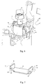
- FIG. 7 represents a possible variant of the contact plate 2 '.
- the end portion 7 ' is strictly identical to the portion 7 of the part described above, with two lateral fins 8 ', 9' and a tooth 5 'anchor.
- the second end portion 6 ′ is positioned so that that it forms a U with the first. It has a 20 'notch allowing the addition of an additional tooth 21 'on a fin 22', in more than tooth 4 'identical to tooth 4 of contact pad 2 previously described.
Abstract
Description
La présente invention a trait à une borne de raccordement d'un conducteur à un appareillage électrique de type modulaire, constitué d'un boítier formé de deux demi-coques assemblées, ou résultant d'un assemblage capot/socle comportant un logement prévu pour accueillir ladite borne. Une telle borne de raccordement comporte une cage logeant une plaquette de contact coopérant avec une vis prévue pour rapprocher ou écarter ladite plaquette d'une des parois de la cage, en vue de fixer par serrage ou de libérer par desserrage ledit conducteur.The present invention relates to a connection terminal of a conductor to modular type electrical equipment, consisting of a housing formed by two assembled half-shells, or resulting from a cover / base assembly comprising a housing planned to accommodate said terminal. Such a connection terminal has a cage housing a cooperating contact plate with a screw provided for bringing said plate apart or apart of one of the walls of the cage, in order to fix by clamping or release by loosening said conductor.
Les appareils électriques modulaires concernés par l'invention comportent en général un nombre pair de bornes servant à les raccorder à des circuits dans lesquels ils assurent une fonction particulière. Ce sont par exemple des disjoncteurs, des auxiliaires de disjoncteurs, des contacteurs, etc.Modular electrical devices concerned by the invention generally have an even number of terminals used to connect to circuits in which they perform a function particular. These are, for example, circuit breakers, auxiliaries circuit breakers, contactors, etc.
Le problème posé et résolu par la présente invention concerne le maintien des cages dans les boítiers. En effet, lorsqu'un opérateur serre ou desserre une connexion par vissage ou dévissage de la vis correspondante, l'effort est transmis à la cage par l'intermédiaire de ladite vis. Or, les cages sont dans la plupart des cas disposées flottantes à l'intérieur des logements prévus dans les boítiers pour les accueillir. Lesdits boítiers étant constitués de deux demi-coques, les logements sont répartis dans ces demi-coques, divisés en deux demi-logements situés en vis à vis, séparés par le plan de séparation des demi-coques. The problem posed and resolved by the present invention relates to the maintenance of the cages in the housings. When an operator tightens or loosens a connection by screwing or unscrewing the screw corresponding, the effort is transmitted to the cage via said screw. However, the cages are in most cases arranged floating inside the housings provided in the boxes for welcome them. Said housings being made up of two half-shells, the housings are distributed in these half-shells, divided in two half-housings located opposite, separated by the plane of separation of the half-shells.
Lorsque le couple exercé sur la vis est transmis à la cage, celle-ci le répercute aux demi-coques, qui ont tendance à s'écarter. En effet, la cage tourne dans son logement, qui n'est pas suffisamment vaste pour permettre cette rotation sans incidence sur les coques. En tout état de cause, pour permettre la réalisation d'une bonne connexion, il est nécessaire de bloquer les cages dans leur logement. Ceci est réalisé par les coques qui les maintiennent, avec une tolérance assez large, d'où l'appellation précitée de "cages flottantes".When the torque exerted on the screw is transmitted to the cage, the latter repercussions on the half-shells, which tend to deviate. Indeed, the cage rotates in its housing, which is not large enough to allow this rotation without affecting the hulls. In any event, for allow a good connection to be made, it is necessary to block the cages in their housing. This is achieved by the hulls which maintain, with a fairly wide tolerance, hence the abovementioned designation of "floating cages".
Cette nécessité de maintenir les cages, afin qu'il y ait une résistance à l'effort de serrage/desserrage, est également au coeur du problème, puisqu'elle est à priori antagoniste de la nécessité d'empêcher les deux coques formant le boítier de se séparer.This need to maintain the cages, so that there is resistance to the tightening / loosening effort is also at the heart of the problem, since it is a priori antagonistic of the need to prevent the two shells forming the housing to separate.
Une solution pourrait être de maintenir la cage en rotation, au moyen par exemple de rivets/bouterolles, ou par une configuration renforcée des logements par ajout de matière. Ces solutions sont cependant théoriques, car la conception actuelle des boítiers, et plus généralement de l'ensemble de l'appareillage électrique, vise à permettre d'une part un gain de place maximal incompatible avec les adjonctions de matière précitées, et d'autre part à aboutir à une automatisation du montage rendant un rivetage ou toute autre fixation équivalente rédhibitoire.One solution could be to keep the cage in rotation, by means of example of rivets / bouterolles, or by a reinforced configuration of housing by adding material. These solutions are however theoretical, because the current design of the boxes, and more generally of the whole electrical equipment, aims to allow on the one hand a maximum space saving incompatible with the aforementioned additions of material, and on the other hand to result in assembly automation making riveting or any other prohibitive equivalent fixation.
Une solution à ce problème a été divulguée dans le brevet européen EP 0 541 459 au nom de MERLIN GÉRIN. Elle consiste à doter la cage de saillies pointues situées diagonalement les unes par rapport aux autres, et orientées sensiblement parallèlement au plan de séparation des demi-coques, dans une direction telles qu'elles s'incrustent dans des parois du logement, dans chaque demi-coque, de sorte qu'en serrant la vis, on aboutit à un rapprochement desdites demi-coques.A solution to this problem has been disclosed in European patent EP 0 541 459 in the name of MERLIN GÉRIN. It consists in providing the cage with projections pointed diagonally to each other, and oriented substantially parallel to the plane of separation of the half-shells, in a direction as they are embedded in the walls of the housing, in each half-shell, so that by tightening the screw, we get closer said half-shells.
Le boítier reste alors jointif au cours de l'opération de serrage. Le mouvement de rotation imprimé à la vis ne se transmet pas à la cage du fait de sa solidarisation au boítier et, en combinaison avec l'ancrage des dents dans les demi-coques, contribue à assurer un serrage efficace du conducteur sans déformation du boítier isolant.The housing then remains joined during the tightening operation. The rotational movement imparted to the screw is not transmitted to the cage due to its attachment to the housing and, in combination with the anchoring of the teeth in the half-shells, contributes to ensuring an effective tightening of the conductor without deformation of the insulating housing.
L'objet de l'invention consiste également à réaliser une borne de connexion qui ne provoque pas de déformation du boítier au cours de l'opération de serrage, mais sans modifier la cage. The object of the invention also consists in producing a terminal for connection which does not cause deformation of the case during the tightening operation, but without modifying the cage.
Selon l'invention, c'est la plaquette de contact logée dans la cage qui comporte des moyens d'ancrage au boítier de l'appareillage électrique.According to the invention, it is the contact plate housed in the cage which includes means for anchoring to the housing of the electrical equipment.
Ainsi, au lieu d'exercer des forces de réaction parallèles à la base du boítier, comme c'était le cas dans le document EP 0 541 459, les forces sont à présent appliquées perpendiculairement à ladite base, et aboutissent également à un effet de rapprochement des deux demi-coques.So instead of exerting reaction forces parallel to the base of the housing, as was the case in document EP 0 541 459, the forces are present applied perpendicular to said base, and terminate also to bring the two half-shells closer together.
L'avantage de cette conception est le suivant : lors d'une opération de raccordement d'un conducteur à une borne, le premier effort exercé par l'opérateur est toujours un effort axial, précédant immédiatement l'application du couple rotatif. Par conséquent, l'ancrage commence d'emblée, dès l'application de la poussée axiale, ce qui procure une garantie maximale d'efficacité et permet de s'affranchir d'éventuels problèmes d'ancrage initial liés à la nécessité d'obtenir des forces de réaction à un couple originellement rotatif.The advantage of this design is as follows: during an operation of connection of a conductor to a terminal, the first force exerted by the operator is always an axial force, immediately preceding the application of the rotary torque. Consequently, anchoring begins immediately, as soon as the application of axial thrust, which provides maximum guarantee efficiency and overcomes any initial anchoring problems linked to the need to obtain reaction forces to a couple originally rotary.
Après l'ancrage initial, dans la configuration de l'invention, le couple exercé sur la vis est transmis aux demi-coques de manière qu'elles se rapprochent au niveau de leurs surfaces de jonction.After the initial anchoring, in the configuration of the invention, the torque exerted on the screw is transmitted to the half-shells so that they approach the level of their junction surfaces.
Plus précisément, les moyens d'ancrage de la plaquette de contact comportent des dents faisant saillies vers des butées pratiquées dans lesdites demi-coques, destinées à s'incruster dans lesdites butées au fur et à mesure de l'exercice du couple de serrage sur la vis.More specifically, the means for anchoring the contact plate have teeth protruding towards stops made in said half-shells, intended to become embedded in said abutments progressively the exercise of the tightening torque on the screw.
Les dents sont situées sur des chants de ladite plaquette de contact orientés à l'opposé de la tête de ladite vis, la pointe de chaque dent s'incrustant selon un axe parallèle à celui de la vis, dans le sens de serrage axial de cette dernière.The teeth are located on the edges of said contact pad oriented opposite the head of said screw, the tip of each tooth encrusting along an axis parallel to that of the screw, in the tightening direction axial of the latter.
De préférence, chaque plaquette de contact comporte au moins une dent coopérant avec une surface d'une butée d'allure sensiblement perpendiculaire à l'axe de la vis et située sur chacune des demi-coques formant le boítier.Preferably, each contact pad has at least one tooth cooperating with a surface of a stop that is substantially perpendicular in shape to the axis of the screw and located on each of the half-shells forming the housing.
De préférence encore, la plaquette de contact comporte un corps central plan doté de deux portions d'extrémités perpendiculaires audit corps, dont l'une est munie d'ailettes latérales dépassant de chaque côté dudit corps central, l'une des dents étant située sur le chant d'extrémité de la portion perpendiculaire sans ailette, décalée vers le côté, l'autre dent étant située sur le chant parallèle de l'ailette située de l'autre côté par rapport à l'axe longitudinal de la plaquette, les deux dents pointant dans la même direction. More preferably, the contact plate has a central body plane provided with two portions of ends perpendicular to said body, of which one is provided with lateral fins projecting from each side of said body central, one of the teeth being located on the end edge of the portion perpendicular without fin, offset to the side, the other tooth being located on the parallel edge of the fin located on the other side with respect to the axis longitudinal of the insert, the two teeth pointing in the same direction.
Selon une variante possible, la plaquette de contact a une forme en U dont l'extrémité des jambages comporte des ailettes latérales dont les chants parallèles orientés vers la base du U comportent chacun une dent, lesdites dents étant situées de part et d'autre de l'axe longitudinal de ladite base du U, une dent étant au surplus localisée sur l'ailette en face de la dent.According to a possible variant, the contact plate has a U-shape of which the ends of the legs have lateral fins whose edges parallel oriented towards the base of the U each have a tooth, said teeth being located on either side of the longitudinal axis of said base of the U, a tooth also being located on the fin opposite the tooth.
D'autres avantages et caractéristiques de la présente invention ressortiront plus clairement de la description détaillée qui suit, dans laquelle un exemple particulier de l'invention sera expliqué en référence aux figures annexées, pour lesquelles :
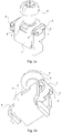
- Les figures 1a et 1b sont des vues en perspective d'une borne de raccordement complète selon l'invention ;
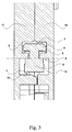
- La figure 2 est une vue en coupe selon le plan de jonction des demi-coques, de ladite borne dans son logement représenté schématiquement ;
- La figure 3 est une coupe de la représentation de la figure 2, vue dans la direction des flèches III ;
- La figure 4 est également une coupe de la représentation de la figure 2, mais vue dans la direction des flèches IV ;
- La figure 5 est enfin une autre coupe de la représentation de la figure 2, vue dans la direction des flèches V ;
- La figure 6 est une vue en perspective d'une borne de raccordement selon la présente invention, dans son environnement immédiat également représenté en figure 2 ; et
- La figure 7 est une variante de la plaquette de contact vue en perspective.
- Figures 1a and 1b are perspective views of a complete connection terminal according to the invention;
- Figure 2 is a sectional view along the junction plane of the half-shells, of said terminal in its housing shown schematically;
- Figure 3 is a section of the representation of Figure 2, seen in the direction of arrows III;
- Figure 4 is also a section of the representation of Figure 2, but seen in the direction of the arrows IV;
- Figure 5 is finally another section of the representation of Figure 2, seen in the direction of the arrows V;
- Figure 6 is a perspective view of a connection terminal according to the present invention, in its immediate environment also shown in Figure 2; and
- Figure 7 is a variant of the contact plate seen in perspective.
Les figures ci-dessus représentent un exemple préférentiel de l'invention,
mais qui ne peut pas être considéré comme limitatif de celle-ci. Ainsi, en
figures 1a et 1b, la borne de raccordement comprend une cage 1 logeant une
plaquette de contact 2 dont le mouvement par rapport à la cage 1 est provoqué
par une vis 3.The figures above represent a preferred example of the invention,
but which cannot be considered as limiting of it. So in
Figures 1a and 1b, the connection terminal comprises a
Les dents 4, 5 faisant saillie de la plaquette de contact 2 sont situées de
part et d'autre de la cage 1, et orientées selon un axe parallèle à celui de la vis
3, pointes dirigées dans le sens du serrage de celle-ci.The
Les portions d'extrémités 6, 7 de la plaquette de serrage sont orientées à
l'opposé l'une de l'autre et présentent donc des chants d'extrémités opposés.
C'est pourquoi, l'une desdites portions est munie d'ailettes latérales 8, 9 offrant
des chants orientés comme le chant d'extrémité de la portion 6. The
Comme cela apparaítra dans les figures suivantes, chaque dent 4, 5
s'incruste au serrage dans des butées moulées dans les demi-coques. Afin
que la fonction principale de l'invention soit réalisée, il importe que chaque
dent coopère avec une butée d'une demi-coque, d'où leur localisation
sensiblement symétrique par rapport à un plan médian longitudinal vertical
coupant la plaquette de contact 2, donnant une représentation équivalente à
celle de la figure 2.As will appear in the following figures, each
Dans cette figure, l'environnement de la borne, constitué par le logement 10
monté dans les demi-coques 11, 12 et les éléments situés au voisinage
immédiat desdits logements 10 sont également représentés. Pour l'intelligence
de l'invention proprement dite, toutefois, seule compte la géométrie des
logements 10, pour deux aspects principaux.In this figure, the terminal environment, consisting of the
En premier lieu, en périphérie de chaque logement, il existe des butées
dans lesquelles les pointes 4, 5 s'ancrent. Dans les figures 2 et suivantes, la
butée associée à la demi-coque 11 est référencée 13, alors que la butée de
l'autre demi-coque 12 porte la référence 14. Du fait de l'ancrage quasi
immédiat de la plaquette de contact 2 dès le début du serrage, ladite plaquette
2 est fixe, et le raccordement du conducteur avec la borne, obtenu par le
coincement de l'extrémité dénudée dudit conducteur entre la plaquette 2 et
l'une des parois de la cage, ne peut être réalisé que si ladite cage est mobile
dans son logement.First, on the periphery of each housing, there are stops
in which the
Ainsi, il se produit un coulissement du seul élément encore doté d'un degré
de liberté dans le logement 10, c'est à dire la cage 1, au fur et à mesure du
serrage ou du desserrage. Lorsqu'aucun conducteur n'est connecté, la cage 1
se situe au voisinage de la paroi du logement 10 la plus proche de la base de
l'appareillage. En position de serrage, ladite cage 1 est au contraire située à
proximité de la paroi du logement 10 entourant la vis 3.Thus, there is a sliding of the only element still endowed with a degree
of freedom in the
Le volume du logement 10 est prévu en conséquence, et autorise un
déplacement de la cage 1 compatible avec les exigences du serrage. Dans
cette configuration, l'ensemble des liaisons mécaniques agit comme un
transformateur de mouvement classique, transformant le mouvement rotatif
imprimé à la vis 3 en un mouvement translatif de la cage 1.The volume of the
Dans l'ultime phase du serrage, le couple appliqué par la vis 3 s'exerce
principalement sur la plaquette de contact 2, laquelle est immobilisée du fait de
l'ancrage des dents 4, 5 dans les butées 13, 14. Les efforts sont néanmoins
répercutés aux deux demi-coques, qui ont tendance à se rapprocher l'une de
l'autre.In the final tightening phase, the torque applied by the
Les deux figures 3 et 4 sont deux vues opposées à partir d'une unique
surface de coupe. Elles montrent clairement les localisations respectives des
dents 4, 5 latéralement par rapport à la plaquette de contact 2, de manière à se
situer chacune dans un demi-logement de chaque demi-coque 11, 12.The two figures 3 and 4 are two opposite views from a single
cutting surface. They clearly show the respective locations of
Le principal intérêt de la figure 5 est de montrer le positionnement relatif
axial de la cage 1 et de la plaquette de contact 2. En outre, le plan de coupe,
sur la partie gauche de la figure, passe dans la dent 5 dont on voit le
positionnement exact d'une part par rapport à la portion d'extrémité 7, et
d'autre part sur la butée 14.The main interest of figure 5 is to show the relative positioning
axial of the
La figure 6 reprend les éléments des figures précédentes 2 à 5, mais en
perspective. Elle met en lumière la coopération de la dent 4 avec la butée 13.
Elle précise également la configuration de l'ensemble cage 1 / plaquette de
contact 2 : la cage 1 est logée dans le volume 10, alors que les portions
d'extrémités 6 et 7 de la plaquette de contact 2 sont nichées à l'extérieur dudit
volume, et n'entravent donc pas la course de la cage 1 lorsqu'elle se déplace
en translation rectiligne.Figure 6 shows the elements of the previous figures 2 to 5, but in
perspective. It highlights the cooperation of
La figure 7 représente une variante possible de la plaquette de contact 2'.
La portion d'extrémité 7' est strictement identique à la portion 7 de la pièce
décrite précédemment, avec deux ailettes latérales 8', 9' et une dent
d'ancrage 5'.FIG. 7 represents a possible variant of the contact plate 2 '.
The end portion 7 'is strictly identical to the
En revanche, la seconde portion d'extrémité 6' est positionnée de telle sorte
qu'elle forme un U avec la première. Elle comporte une échancrure 20'
permettant l'adjonction d'une dent 21' supplémentaire sur une ailette 22', en
plus de la dent 4' identique à la dent 4 de la plaquette de contact 2
précédemment décrite.On the other hand, the
Les butées des demi-coques doivent bien entendu être adaptées en
conséquence, ainsi que les niches disposées en périphérie des logements 10.
Ainsi, l'adjonction d'une dent 21' impose par exemple l'adjonction d'une butée
(éléments non représentés).The stops of the half-shells must of course be adapted in
Consequently, as well as the recesses arranged on the periphery of the
L'invention et sa variante, telles que décrites, ne sont pas limitatives de l'invention, et ne doivent être considérés que comme des exemples d'application.The invention and its variant, as described, are not limitative of the invention, and should only be considered as examples of application.
Claims (6)
caractérisée en ce que ladite plaquette de contact 2 comporte des moyens d'ancrage 4, 5 aux deux demi-coques 11, 12, afin que le couple exercé sur la vis 3 pendant le serrage soit transmis auxdites demi-coques 11, 12 de manière qu'elles se resserrent au niveau de leurs surfaces de jonction.Terminal for connecting a conductor to an electrical appliance of the modular type, disposed in a box formed by two half-shells 11, 12 assembled in a housing 10 provided for this purpose, said connection terminal comprising a cage 1 housing a plate of contact 2 cooperating with a screw 3 with a view to clamping or releasing said conductor by loosening,
characterized in that said contact plate 2 comprises means 4, 5 for anchoring the two half-shells 11, 12, so that the torque exerted on the screw 3 during tightening is transmitted to said half-shells 11, 12 so that they tighten at their junction surfaces.
Priority Applications (2)
| Application Number | Priority Date | Filing Date | Title |
|---|---|---|---|
| DE1996602758 DE69602758T2 (en) | 1996-11-29 | 1996-11-29 | Conductor connection terminal of a modular electrical device |
| EP19960440102 EP0847105B1 (en) | 1996-11-29 | 1996-11-29 | Wire connecting terminal in a modular electrical device |
Applications Claiming Priority (1)
| Application Number | Priority Date | Filing Date | Title |
|---|---|---|---|
| EP19960440102 EP0847105B1 (en) | 1996-11-29 | 1996-11-29 | Wire connecting terminal in a modular electrical device |
Publications (2)
| Publication Number | Publication Date |
|---|---|
| EP0847105A1 true EP0847105A1 (en) | 1998-06-10 |
| EP0847105B1 EP0847105B1 (en) | 1999-06-02 |
Family
ID=8225426
Family Applications (1)
| Application Number | Title | Priority Date | Filing Date |
|---|---|---|---|
| EP19960440102 Expired - Lifetime EP0847105B1 (en) | 1996-11-29 | 1996-11-29 | Wire connecting terminal in a modular electrical device |
Country Status (2)
| Country | Link |
|---|---|
| EP (1) | EP0847105B1 (en) |
| DE (1) | DE69602758T2 (en) |
Cited By (5)
| Publication number | Priority date | Publication date | Assignee | Title |
|---|---|---|---|---|
| WO2003041226A1 (en) * | 2001-11-06 | 2003-05-15 | Abb Service S.R.L. | Terminal for low voltage modular device |
| DE10111431B4 (en) * | 2000-03-10 | 2008-09-25 | Schneider Electric Industries S.A. | Conductor terminal |
| EP2019449A2 (en) | 2007-07-26 | 2009-01-28 | Abb Ag | Screw-clamp and method for manufacturing thereof |
| CN103138058A (en) * | 2011-12-01 | 2013-06-05 | 西门子公司 | Cable connector base |
| CN106911054A (en) * | 2017-04-01 | 2017-06-30 | 菲尼克斯亚太电气(南京)有限公司 | A kind of external switch screw adapter assembly |
Families Citing this family (1)
| Publication number | Priority date | Publication date | Assignee | Title |
|---|---|---|---|---|
| DE102007006367A1 (en) * | 2007-02-08 | 2008-08-21 | Siemens Ag | Circuit breaker with terminal |
Citations (5)
| Publication number | Priority date | Publication date | Assignee | Title |
|---|---|---|---|---|
| US3559156A (en) * | 1968-01-18 | 1971-01-26 | Westinghouse Electric Corp | Electrical device with improved terminal means |
| DE1790153A1 (en) * | 1967-09-29 | 1972-01-20 | Telemeccanica Elettrica Ohg Ri | Terminal for connecting electrical conductors |
| DE3417010A1 (en) * | 1984-05-09 | 1985-11-14 | Karl Lumberg GmbH & Co, 5885 Schalksmühle | ELECTRICAL TERMINAL |
| EP0541459A1 (en) | 1991-11-07 | 1993-05-12 | Schneider Electric Sa | Clamping screw for an electrical device with moulded insulating housing |
| DE4329097C1 (en) * | 1993-08-30 | 1994-09-29 | Lumberg Karl Gmbh & Co | Electrical connecting terminal for printed circuit boards, and a method for its production |
-
1996
- 1996-11-29 DE DE1996602758 patent/DE69602758T2/en not_active Expired - Lifetime
- 1996-11-29 EP EP19960440102 patent/EP0847105B1/en not_active Expired - Lifetime
Patent Citations (5)
| Publication number | Priority date | Publication date | Assignee | Title |
|---|---|---|---|---|
| DE1790153A1 (en) * | 1967-09-29 | 1972-01-20 | Telemeccanica Elettrica Ohg Ri | Terminal for connecting electrical conductors |
| US3559156A (en) * | 1968-01-18 | 1971-01-26 | Westinghouse Electric Corp | Electrical device with improved terminal means |
| DE3417010A1 (en) * | 1984-05-09 | 1985-11-14 | Karl Lumberg GmbH & Co, 5885 Schalksmühle | ELECTRICAL TERMINAL |
| EP0541459A1 (en) | 1991-11-07 | 1993-05-12 | Schneider Electric Sa | Clamping screw for an electrical device with moulded insulating housing |
| DE4329097C1 (en) * | 1993-08-30 | 1994-09-29 | Lumberg Karl Gmbh & Co | Electrical connecting terminal for printed circuit boards, and a method for its production |
Cited By (8)
| Publication number | Priority date | Publication date | Assignee | Title |
|---|---|---|---|---|
| DE10111431B4 (en) * | 2000-03-10 | 2008-09-25 | Schneider Electric Industries S.A. | Conductor terminal |
| WO2003041226A1 (en) * | 2001-11-06 | 2003-05-15 | Abb Service S.R.L. | Terminal for low voltage modular device |
| EP2019449A2 (en) | 2007-07-26 | 2009-01-28 | Abb Ag | Screw-clamp and method for manufacturing thereof |
| EP2019449A3 (en) * | 2007-07-26 | 2009-12-16 | Abb Ag | Screw-clamp and method for manufacturing thereof |
| CN101355199B (en) * | 2007-07-26 | 2012-11-28 | Abb股份有限公司 | Screw connecting terminal and method for its production |
| CN103138058A (en) * | 2011-12-01 | 2013-06-05 | 西门子公司 | Cable connector base |
| CN106911054A (en) * | 2017-04-01 | 2017-06-30 | 菲尼克斯亚太电气(南京)有限公司 | A kind of external switch screw adapter assembly |
| CN106911054B (en) * | 2017-04-01 | 2024-03-19 | 菲尼克斯亚太电气(南京)有限公司 | External switch screw switching assembly |
Also Published As
| Publication number | Publication date |
|---|---|
| DE69602758T2 (en) | 2000-03-02 |
| EP0847105B1 (en) | 1999-06-02 |
| DE69602758D1 (en) | 1999-07-08 |
Similar Documents
| Publication | Publication Date | Title |
|---|---|---|
| EP0847105B1 (en) | Wire connecting terminal in a modular electrical device | |
| EP0784355B1 (en) | Interconnection arrangement for an electrical apparatus, especially for a junction box type apparatus, and a housing comprising such an arrangement | |
| FR2808618A1 (en) | CIRCUIT BREAKER COMPRISING, IN AN ENCLOSURE FILLED WITH A DIELECTRIC GAS UNDER PRESSURE, A MOBILE ASSEMBLY | |
| EP0893846B1 (en) | Electrical apparatus having a fixed contact carrier and a connecting terminal | |
| EP0559585A1 (en) | Connector terminal with caliper of variable thickness and mounted nut | |
| FR2601512A1 (en) | ELECTRICAL CONNECTOR WITH ZERO INSERTION FORCE | |
| EP0541459B1 (en) | Clamping screw for an electrical device with moulded insulating housing | |
| FR2766628A1 (en) | Tool to align multiple electric terminations with modules receiving them | |
| EP0552114B1 (en) | Connection terminal for a modular electrical assembly | |
| FR2752647A1 (en) | TERMINAL DEVICE FOR ELECTRICAL EQUIPMENT | |
| FR2750803A1 (en) | Electrical connector for switching module | |
| FR2488452A1 (en) | TERMINAL FOR QUICK ANCHORING OF CONDUCTORS ON "OF" ELECTRICAL DEVICES | |
| EP1531525A1 (en) | Cable clamp with enlarged clamping surface and terminal block comprising it | |
| FR2709883A1 (en) | Electric contact with elastic return. | |
| EP0521803B1 (en) | Electrical connection and supply device | |
| FR2463514A1 (en) | Battery connector with clamping lever - has cam mounted on spindle between lever and adjacent flange | |
| FR2843496A1 (en) | Exterior cable junction box connection having isolating box with spring strip loop having free end tool positioned active cable position and tool clamped during operation | |
| EP2135328B1 (en) | Junction block and linking rod | |
| FR2597664A1 (en) | Electrical connection device of the insulation-displacement type | |
| FR2894721A1 (en) | Conductive pad and stripped electric wire`s conductors connecting clamping saddle, has clamping screw with flange and screwed in wall of casing opposite to surface, where screw clamps one conductor on another conductor placed on surface | |
| EP0763871B1 (en) | Electrical installation apparatus connecting terminal | |
| FR2858119A1 (en) | Electrical connection device, has screw that is rotated through external operation tool so that locking unit isolated from exterior is moved between locking and disengagement positions | |
| EP0893851A1 (en) | Electric contact with elastic return | |
| FR2864712A1 (en) | Low voltage apparatus e.g. electric terminal block, for standardized support rail, has two clamps, each with two branches having free ends provided with notches that cooperate with rail to clamp apparatus on rail | |
| FR2538626A2 (en) | Thermocouple connector |
Legal Events
| Date | Code | Title | Description |
|---|---|---|---|
| PUAI | Public reference made under article 153(3) epc to a published international application that has entered the european phase |
Free format text: ORIGINAL CODE: 0009012 |
|
| 17P | Request for examination filed |
Effective date: 19961210 |
|
| AK | Designated contracting states |
Kind code of ref document: A1 Designated state(s): CH DE ES FI FR IT LI SE |
|
| GRAG | Despatch of communication of intention to grant |
Free format text: ORIGINAL CODE: EPIDOS AGRA |
|
| GRAG | Despatch of communication of intention to grant |
Free format text: ORIGINAL CODE: EPIDOS AGRA |
|
| GRAH | Despatch of communication of intention to grant a patent |
Free format text: ORIGINAL CODE: EPIDOS IGRA |
|
| GRAH | Despatch of communication of intention to grant a patent |
Free format text: ORIGINAL CODE: EPIDOS IGRA |
|
| AKX | Designation fees paid |
Free format text: CH DE ES FI FR IT LI SE |
|
| RBV | Designated contracting states (corrected) |
Designated state(s): CH DE ES FI FR IT LI SE |
|
| GRAA | (expected) grant |
Free format text: ORIGINAL CODE: 0009210 |
|
| AK | Designated contracting states |
Kind code of ref document: B1 Designated state(s): CH DE ES FI FR IT LI SE |
|
| PG25 | Lapsed in a contracting state [announced via postgrant information from national office to epo] |
Ref country code: SE Free format text: THE PATENT HAS BEEN ANNULLED BY A DECISION OF A NATIONAL AUTHORITY Effective date: 19990602 Ref country code: FI Free format text: LAPSE BECAUSE OF NON-PAYMENT OF DUE FEES Effective date: 19990602 Ref country code: ES Free format text: THE PATENT HAS BEEN ANNULLED BY A DECISION OF A NATIONAL AUTHORITY Effective date: 19990602 |
|
| REG | Reference to a national code |
Ref country code: CH Ref legal event code: EP |
|
| REF | Corresponds to: |
Ref document number: 69602758 Country of ref document: DE Date of ref document: 19990708 |
|
| ITF | It: translation for a ep patent filed |
Owner name: STUDIO TORTA S.R.L. |
|
| PLBE | No opposition filed within time limit |
Free format text: ORIGINAL CODE: 0009261 |
|
| STAA | Information on the status of an ep patent application or granted ep patent |
Free format text: STATUS: NO OPPOSITION FILED WITHIN TIME LIMIT |
|
| 26N | No opposition filed | ||
| REG | Reference to a national code |
Ref country code: CH Ref legal event code: PL |
|
| PGFP | Annual fee paid to national office [announced via postgrant information from national office to epo] |
Ref country code: CH Payment date: 20010806 Year of fee payment: 5 |
|
| REG | Reference to a national code |
Ref country code: CH Ref legal event code: AEN Free format text: LE BREVET A ETE REACTIVE SELON LA DEMANDE DE POURSUITE DE LA PROCEDURE DU 06.08.2001. |
|
| PG25 | Lapsed in a contracting state [announced via postgrant information from national office to epo] |
Ref country code: LI Free format text: LAPSE BECAUSE OF NON-PAYMENT OF DUE FEES Effective date: 20011130 Ref country code: CH Free format text: LAPSE BECAUSE OF NON-PAYMENT OF DUE FEES Effective date: 20011130 |
|
| REG | Reference to a national code |
Ref country code: CH Ref legal event code: PL |
|
| REG | Reference to a national code |
Ref country code: FR Ref legal event code: PLFP Year of fee payment: 20 |
|
| PGFP | Annual fee paid to national office [announced via postgrant information from national office to epo] |
Ref country code: IT Payment date: 20151113 Year of fee payment: 20 Ref country code: DE Payment date: 20151119 Year of fee payment: 20 |
|
| PGFP | Annual fee paid to national office [announced via postgrant information from national office to epo] |
Ref country code: FR Payment date: 20151123 Year of fee payment: 20 |
|
| REG | Reference to a national code |
Ref country code: DE Ref legal event code: R071 Ref document number: 69602758 Country of ref document: DE |