EP0845397A2 - Régulateur de pression pour systèmes de freinage électropneumatiques pour véhicules, notamment véhicules utilitaires - Google Patents
Régulateur de pression pour systèmes de freinage électropneumatiques pour véhicules, notamment véhicules utilitaires Download PDFInfo
- Publication number
- EP0845397A2 EP0845397A2 EP97119849A EP97119849A EP0845397A2 EP 0845397 A2 EP0845397 A2 EP 0845397A2 EP 97119849 A EP97119849 A EP 97119849A EP 97119849 A EP97119849 A EP 97119849A EP 0845397 A2 EP0845397 A2 EP 0845397A2
- Authority
- EP
- European Patent Office
- Prior art keywords
- valve
- pressure
- inlet
- brake
- control device
- Prior art date
- Legal status (The legal status is an assumption and is not a legal conclusion. Google has not performed a legal analysis and makes no representation as to the accuracy of the status listed.)
- Granted
Links
Images


Classifications
-
- B—PERFORMING OPERATIONS; TRANSPORTING
- B60—VEHICLES IN GENERAL
- B60T—VEHICLE BRAKE CONTROL SYSTEMS OR PARTS THEREOF; BRAKE CONTROL SYSTEMS OR PARTS THEREOF, IN GENERAL; ARRANGEMENT OF BRAKING ELEMENTS ON VEHICLES IN GENERAL; PORTABLE DEVICES FOR PREVENTING UNWANTED MOVEMENT OF VEHICLES; VEHICLE MODIFICATIONS TO FACILITATE COOLING OF BRAKES
- B60T8/00—Arrangements for adjusting wheel-braking force to meet varying vehicular or ground-surface conditions, e.g. limiting or varying distribution of braking force
- B60T8/32—Arrangements for adjusting wheel-braking force to meet varying vehicular or ground-surface conditions, e.g. limiting or varying distribution of braking force responsive to a speed condition, e.g. acceleration or deceleration
- B60T8/34—Arrangements for adjusting wheel-braking force to meet varying vehicular or ground-surface conditions, e.g. limiting or varying distribution of braking force responsive to a speed condition, e.g. acceleration or deceleration having a fluid pressure regulator responsive to a speed condition
- B60T8/36—Arrangements for adjusting wheel-braking force to meet varying vehicular or ground-surface conditions, e.g. limiting or varying distribution of braking force responsive to a speed condition, e.g. acceleration or deceleration having a fluid pressure regulator responsive to a speed condition including a pilot valve responding to an electromagnetic force
- B60T8/3615—Electromagnetic valves specially adapted for anti-lock brake and traction control systems
- B60T8/3655—Continuously controlled electromagnetic valves
- B60T8/366—Valve details
- B60T8/367—Seat valves, e.g. poppet valves
-
- B—PERFORMING OPERATIONS; TRANSPORTING
- B60—VEHICLES IN GENERAL
- B60T—VEHICLE BRAKE CONTROL SYSTEMS OR PARTS THEREOF; BRAKE CONTROL SYSTEMS OR PARTS THEREOF, IN GENERAL; ARRANGEMENT OF BRAKING ELEMENTS ON VEHICLES IN GENERAL; PORTABLE DEVICES FOR PREVENTING UNWANTED MOVEMENT OF VEHICLES; VEHICLE MODIFICATIONS TO FACILITATE COOLING OF BRAKES
- B60T13/00—Transmitting braking action from initiating means to ultimate brake actuator with power assistance or drive; Brake systems incorporating such transmitting means, e.g. air-pressure brake systems
- B60T13/10—Transmitting braking action from initiating means to ultimate brake actuator with power assistance or drive; Brake systems incorporating such transmitting means, e.g. air-pressure brake systems with fluid assistance, drive, or release
- B60T13/66—Electrical control in fluid-pressure brake systems
- B60T13/68—Electrical control in fluid-pressure brake systems by electrically-controlled valves
- B60T13/683—Electrical control in fluid-pressure brake systems by electrically-controlled valves in pneumatic systems or parts thereof
-
- B—PERFORMING OPERATIONS; TRANSPORTING
- B60—VEHICLES IN GENERAL
- B60T—VEHICLE BRAKE CONTROL SYSTEMS OR PARTS THEREOF; BRAKE CONTROL SYSTEMS OR PARTS THEREOF, IN GENERAL; ARRANGEMENT OF BRAKING ELEMENTS ON VEHICLES IN GENERAL; PORTABLE DEVICES FOR PREVENTING UNWANTED MOVEMENT OF VEHICLES; VEHICLE MODIFICATIONS TO FACILITATE COOLING OF BRAKES
- B60T8/00—Arrangements for adjusting wheel-braking force to meet varying vehicular or ground-surface conditions, e.g. limiting or varying distribution of braking force
- B60T8/32—Arrangements for adjusting wheel-braking force to meet varying vehicular or ground-surface conditions, e.g. limiting or varying distribution of braking force responsive to a speed condition, e.g. acceleration or deceleration
- B60T8/321—Arrangements for adjusting wheel-braking force to meet varying vehicular or ground-surface conditions, e.g. limiting or varying distribution of braking force responsive to a speed condition, e.g. acceleration or deceleration deceleration
- B60T8/3255—Systems in which the braking action is dependent on brake pedal data
- B60T8/327—Pneumatic systems
-
- B—PERFORMING OPERATIONS; TRANSPORTING
- B60—VEHICLES IN GENERAL
- B60T—VEHICLE BRAKE CONTROL SYSTEMS OR PARTS THEREOF; BRAKE CONTROL SYSTEMS OR PARTS THEREOF, IN GENERAL; ARRANGEMENT OF BRAKING ELEMENTS ON VEHICLES IN GENERAL; PORTABLE DEVICES FOR PREVENTING UNWANTED MOVEMENT OF VEHICLES; VEHICLE MODIFICATIONS TO FACILITATE COOLING OF BRAKES
- B60T8/00—Arrangements for adjusting wheel-braking force to meet varying vehicular or ground-surface conditions, e.g. limiting or varying distribution of braking force
- B60T8/32—Arrangements for adjusting wheel-braking force to meet varying vehicular or ground-surface conditions, e.g. limiting or varying distribution of braking force responsive to a speed condition, e.g. acceleration or deceleration
- B60T8/34—Arrangements for adjusting wheel-braking force to meet varying vehicular or ground-surface conditions, e.g. limiting or varying distribution of braking force responsive to a speed condition, e.g. acceleration or deceleration having a fluid pressure regulator responsive to a speed condition
- B60T8/36—Arrangements for adjusting wheel-braking force to meet varying vehicular or ground-surface conditions, e.g. limiting or varying distribution of braking force responsive to a speed condition, e.g. acceleration or deceleration having a fluid pressure regulator responsive to a speed condition including a pilot valve responding to an electromagnetic force
- B60T8/3605—Arrangements for adjusting wheel-braking force to meet varying vehicular or ground-surface conditions, e.g. limiting or varying distribution of braking force responsive to a speed condition, e.g. acceleration or deceleration having a fluid pressure regulator responsive to a speed condition including a pilot valve responding to an electromagnetic force wherein the pilot valve is mounted in a circuit controlling the working fluid system
-
- B—PERFORMING OPERATIONS; TRANSPORTING
- B60—VEHICLES IN GENERAL
- B60T—VEHICLE BRAKE CONTROL SYSTEMS OR PARTS THEREOF; BRAKE CONTROL SYSTEMS OR PARTS THEREOF, IN GENERAL; ARRANGEMENT OF BRAKING ELEMENTS ON VEHICLES IN GENERAL; PORTABLE DEVICES FOR PREVENTING UNWANTED MOVEMENT OF VEHICLES; VEHICLE MODIFICATIONS TO FACILITATE COOLING OF BRAKES
- B60T8/00—Arrangements for adjusting wheel-braking force to meet varying vehicular or ground-surface conditions, e.g. limiting or varying distribution of braking force
- B60T8/32—Arrangements for adjusting wheel-braking force to meet varying vehicular or ground-surface conditions, e.g. limiting or varying distribution of braking force responsive to a speed condition, e.g. acceleration or deceleration
- B60T8/34—Arrangements for adjusting wheel-braking force to meet varying vehicular or ground-surface conditions, e.g. limiting or varying distribution of braking force responsive to a speed condition, e.g. acceleration or deceleration having a fluid pressure regulator responsive to a speed condition
- B60T8/36—Arrangements for adjusting wheel-braking force to meet varying vehicular or ground-surface conditions, e.g. limiting or varying distribution of braking force responsive to a speed condition, e.g. acceleration or deceleration having a fluid pressure regulator responsive to a speed condition including a pilot valve responding to an electromagnetic force
- B60T8/3615—Electromagnetic valves specially adapted for anti-lock brake and traction control systems
- B60T8/3675—Electromagnetic valves specially adapted for anti-lock brake and traction control systems integrated in modulator units
Definitions
- the invention relates to a pressure control device according to the generic term of Claim 1.
- Valves are used that either fulfill both functions can, or separate valves for each function separately. It come under other for use proportional solenoid valves with and without relay valve, with and without ABS pressure control valves, furthermore double solenoid valves for Pilot control of a relay valve, with and without ABS pressure control valves, as well current controlled pilot solenoid valves with seat valves, the latter for both Functions.
- pressure control devices When trying to enable sensitive settings of the consumer pressure, pressure control devices have been developed, in which at the consumer side Monitoring of consumer pressure through a pressure sensor inlet and Exhaust valves are provided which cooperate with pilot valves, such that in the course of the electrical control of the inlet and Exhaust valves actuating electromagnets a throttled time Opening of the pilot valves is made possible. With increasing excitement of the Actuating magnets close the pilot valves and the actual ones Main valves open in large cross sections.
- the desired sensitive feeding of the In such control devices consumer pressure is characterized by a large number of Parameters determined; there are also intermediate or floating positions of the Main valves are given, which are defined depending on the excitation current have to.
- the structural complexity of such pressure regulating devices is accordingly considerable, is also functional accuracy at different temperature and Pressure conditions required.
- the object of the invention is a Pressure control device of the generic type with simple means so to design that they perform both service brake and ABS functions can and is particularly suitable for both sensitive pressure changes Mediate service braking as well as rapid pressure changes enable if emergency braking or ABS functions require it. Also supposed to the construction of such pressure regulating devices the use of Pre-control units can be dispensed with.
- both the service brake function as the ABS function can also be implemented with a module, furthermore there is Air consumption as with current brake systems, i.e. no increased air consumption through clocking valves. There are also no noises to be accepted, as with Clock valves or pulsating valves occur adversely. It’s also an advantage that the facility through its current regulation essentially works independently of temperature.
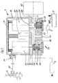
- FIG. 1 of the drawing is a first embodiment of an electropneumatic Brake system using the pressure control device 1 according to the invention shown.
- the pressure control device 1 is shown in FIG Connection to a compressed air supply 3, a brake cylinder 5 for a schematic reproduced wheel 7 of the vehicle and an electropneumatic Brake value transmitter 9 in the form of a foot brake valve.
- the pressure control device 1 consists of two functional units, one shown schematically, electronic control unit 11 and a valve device 13, which in controlled below by means of the electronic control unit the connection between the pressure medium source, i.e. the compressed air supply 3, and the consumer, i.e. the brake cylinder 5, as well as the connection between the brake cylinder 5 and the pressure relief, i.e. in the illustrated Example with the outside air to control.
- the electro-pneumatic brake value transmitter 9 is over with its electrical part a control line 15 and a plug 17 to the electronic control unit 11 connected.
- the electronic control unit 11 is located within a Housing 19, which with the housing 21 below in the drawing the valve device 13 is connected; in the housing 19 of the electronic Control unit are an electromagnet 23 with one of its armatures formed actuating plunger 25, a further electromagnet 27 with a Actuating plunger 29 and one connected to the electronic control unit 11 Pressure sensor 31.
- the two electromagnets 23 and 27 are also with the electronic control unit 11 and are connected in accordance with the Actuation of the brake value transmitter 9 and the one implemented by the pressure sensor Electronic control unit 11 incoming measured variables regulated.
- the valve device 13 with a Inlet valve 33 and an outlet valve 35 provided.
- the inlet valve monitors the Connection between an inlet 37 and a pressure medium chamber 39, which via an outlet 41 to the consumer, i.e. connected to the brake cylinder 5 is.
- the outlet valve 35 monitors the connection between the consumer 5 and a further outlet 43, which is connected to the atmosphere, that is actual relief device forms.
- the outlet 43 communicates with the outside air by means of a silencer 45.
- the two valves are in their starting position reproduced, i.e. the inlet valve 33 blocks the connection between the Compressed air supply 3 and the consumer, while the outlet valve connects in Releases to vent, i.e. the brakes of the vehicle are deflated.
- the two electromagnets are without current, the retracted position of the Actuating plunger 25 and the extended position of the actuating plunger 29 e.g. are brought about under spring action.
- the inlet valve 33 is provided with a valve piston 47 which acts against the force a spring 49 can be actuated and means for pressure relief in a conventional manner has, i.e. in the illustrated embodiment holes, which are characterized by extend the valve piston such that on both ends of the valve piston Pressure relief exists.
- the valve piston 47 is in its immediate vicinity Inlet area, i.e. at its end facing the supply pressure with a special contour design, which allows the air flow to be targeted to be metered by means of a flow cross-section that can be changed over the piston stroke.
- the special shape at the inlet end of the valve piston 47 is one Contouring adapted to the inlet cross-section of the valve housing, so that between Valve housing inner circumference and outer circumference of the valve piston 47 die the aforementioned targeted air metering is made possible in accordance with the stroke.
- Fig. 2 The drawing shows various contours at the inlet end of the valve piston 47 in Assignment to the specially designed contouring of the valve housing reproduced.
- FIG. 3 of the drawing illustrates the according to the in Fig.
- the contours shown in FIG. 2 made it possible for flow cross sections to be dependent from the stroke of the valve piston displaceable by the actuating tappet 25.
- the Flow cross sections Q1, Q2 and Q3 according to FIG. 3 are the contours A, B and C. assigned to FIG. 2. It can be seen that the contour A is linear changes in the flow cross-section, while the contour B depending on the stroke, a complete opening of the cross-section according to the previous one linear increase in cross section.
- contour C the profile is between Valve piston 47 and valve housing of different types, i.e. the arcuate course at the inlet end of the valve lifter corresponds to that in FIG. 3 reproduced arcuate course of the flow cross-section, which is formed between the valve housing and the inlet end of the valve piston.
- a target braking signal specified by the brake value transmitter 9 is generated supplied to the electronic control unit 11 via the plug 17.
- the electronic control unit closes over the electromagnet 27 and its Actuating plunger 29, the outlet valve 35 (Fig. 1) and activated by means of Electromagnet 23, the inlet valve 33.
- the pressure control device is here with a provided additional brake pressure retention valve 53; this works with an input and Outlet valve 55 together, to which the compressed air supply 3 is connected.
- the inlet and outlet valve 55 is opened simultaneously, such that by the supply pressure from the compressed air supply 3 Brake pressure retention valve 53 in the closed position on the valve seat on the housing 57 is held.
- the inlet valve 33 is open, the pressurization of the Consumer, i.e. of the brake cylinder 5 in the with reference to FIG. 1st explained way.
- Exhaust valve 35 actuated by the solenoid 27, i.e. the valve piston it is directed downwards into the open position (FIG. 4), such that the connection between the consumer and the relief device consists.
- the brake pressure retention valve 53 takes the open in this case Position one, because of the compressed air supply 3 through the inlet and outlet valve 55 pressure present when the electropneumatic control circuit is switched off shut off and the brake pressure retention valve via the open inlet and Exhaust valve 55 is vented as shown in Fig. 4.
- inlet valve 33 and outlet valve 35 in In contrast to the embodiment of FIG. 1 can be designed identically.
Landscapes
- Engineering & Computer Science (AREA)
- Physics & Mathematics (AREA)
- Electromagnetism (AREA)
- Transportation (AREA)
- Mechanical Engineering (AREA)
- Fluid Mechanics (AREA)
- Braking Systems And Boosters (AREA)
- Regulating Braking Force (AREA)
- Valves And Accessory Devices For Braking Systems (AREA)
Applications Claiming Priority (2)
| Application Number | Priority Date | Filing Date | Title |
|---|---|---|---|
| DE19649402A DE19649402A1 (de) | 1996-11-28 | 1996-11-28 | Druckregelvorrichtung für elektropneumatische Bremsanlagen von Fahrzeugen, insbesondere Nutzfahrzeugen |
| DE19649402 | 1996-11-28 |
Publications (4)
| Publication Number | Publication Date |
|---|---|
| EP0845397A2 true EP0845397A2 (fr) | 1998-06-03 |
| EP0845397A3 EP0845397A3 (fr) | 1999-03-24 |
| EP0845397B1 EP0845397B1 (fr) | 2002-03-06 |
| EP0845397B2 EP0845397B2 (fr) | 2008-03-26 |
Family
ID=7813074
Family Applications (1)
| Application Number | Title | Priority Date | Filing Date |
|---|---|---|---|
| EP97119849A Expired - Lifetime EP0845397B2 (fr) | 1996-11-28 | 1997-11-13 | Régulateur de pression pour systèmes de freinage électropneumatiques pour véhicules, notamment véhicules utilitaires |
Country Status (4)
| Country | Link |
|---|---|
| US (1) | US6126244A (fr) |
| EP (1) | EP0845397B2 (fr) |
| JP (1) | JPH10291472A (fr) |
| DE (2) | DE19649402A1 (fr) |
Cited By (12)
| Publication number | Priority date | Publication date | Assignee | Title |
|---|---|---|---|---|
| WO2000002755A1 (fr) * | 1998-07-08 | 2000-01-20 | Continental Teves Ag & Co. Ohg | Regulateur de freinage |
| WO2000071400A1 (fr) | 1999-05-21 | 2000-11-30 | Knorr-Bremse Systeme für Nutzfahrzeuge GmbH | Systeme de freinage a regulation electronique |
| EP0888943B1 (fr) * | 1997-05-20 | 2001-10-10 | Westinghouse Air Brake Company | Ensemble de valve de freinage pour véhicule ferroviaire |
| EP1319566A3 (fr) * | 2001-12-14 | 2003-10-29 | WABCO GmbH & CO. OHG | Ensemble pour solénoide et capteur de pression |
| EP1544072A1 (fr) * | 2003-12-17 | 2005-06-22 | KNORR-BREMSE SYSTEME FÜR NUTZFAHRZEUGE GmbH | Système de freinage à commande électronique |
| FR2923574A1 (fr) * | 2007-11-06 | 2009-05-15 | Wabco Gmbh | Unite d'electrovannes pour une commande electropneumatique, notamment pour un modulateur de pression d'un vehicule utilitaire |
| WO2010094481A2 (fr) | 2009-02-20 | 2010-08-26 | Knorr-Bremse Systeme für Nutzfahrzeuge GmbH | Module de régulation de pression électro-pneumatique avec canaux de régulation de pression sur circuits pneumatiques séparés |
| EP1889766A3 (fr) * | 2006-08-18 | 2014-06-11 | WABCO GmbH | Système de frein électropneumatique et procédé destiné à la commande d'un système de frein électropneumatique |
| EP3256356B1 (fr) | 2015-02-13 | 2019-01-02 | KNORR-BREMSE Systeme für Nutzfahrzeuge GmbH | Dispositif de frein de service électropneumatique d'un véhicule à réduction du bruit lors du relâchement du frein ainsi que son procédé de commande |
| DE102018123996A1 (de) * | 2018-09-28 | 2020-04-02 | Knorr-Bremse Systeme für Nutzfahrzeuge GmbH | Als Baueinheit ausgeführtes zentrales elektro-pneumatisches Druckregelmodul mit integriertem zentralen Bremssteuergerät |
| DE102018123997A1 (de) * | 2018-09-28 | 2020-04-02 | Knorr-Bremse Systeme für Nutzfahrzeuge GmbH | Als Baueinheit ausgeführtes elektro-pneumatisches Druckregelmodul mit integriertem Inertialsensor |
| CN114734971A (zh) * | 2022-04-29 | 2022-07-12 | 三一电动车科技有限公司 | 车辆制动控制系统、控制方法及车辆 |
Families Citing this family (18)
| Publication number | Priority date | Publication date | Assignee | Title |
|---|---|---|---|---|
| WO1999050115A1 (fr) * | 1998-03-31 | 1999-10-07 | Continental Teves Ag & Co. Ohg | Bloc de composants detecteurs de pression |
| DE19918070B4 (de) * | 1998-06-03 | 2010-07-29 | Knorr-Bremse Systeme für Nutzfahrzeuge GmbH | Druckregelvorrichtung für elektro-pneumatische Bremsanlagen von Fahrzeugen, insbesondere Nutzfahrzeugen |
| DE19928113C1 (de) * | 1999-06-19 | 2000-10-26 | Haldex Brake Prod Gmbh | Anhängerbremsventil für blockiergeschützte Druckluftbremsanlagen von Anhängern |
| US6443536B1 (en) * | 2001-02-01 | 2002-09-03 | Delphi Technologies, Inc. | Brake pressure modulator with pressure sensor manifold |
| DE10107239A1 (de) | 2001-02-16 | 2002-08-29 | Wabco Gmbh & Co Ohg | Steuereinrichtung für Druckmittel |
| US7204566B2 (en) * | 2001-04-17 | 2007-04-17 | Toyota Jidosha Kabushiki Kaisha | Hydraulic braking pressure control unit |
| DE10161497A1 (de) * | 2001-12-14 | 2003-06-26 | Wabco Gmbh & Co Ohg | Magnetspulen-Drucksensoreinheit für mit Magnetregelventilen ausgestattete EBS-Modulatoren von elektronisch geregelten elektro-pneumatischen Bremsanlagen |
| US7798174B2 (en) * | 2003-08-20 | 2010-09-21 | Eaton Corporation | Electric fluid servo valve and method of making same |
| US20060045749A1 (en) * | 2004-08-30 | 2006-03-02 | Powermate Corporation | Air compressor utilizing an electronic control system |
| JP5168618B2 (ja) * | 2007-08-08 | 2013-03-21 | ヴアブコ・ゲゼルシヤフト・ミツト・ベシユレンクテル・ハフツング | 電気−空気圧制動システム及び電気−空気圧制動システムの制御方法 |
| US20090050219A1 (en) * | 2007-08-21 | 2009-02-26 | Briggs And Stratton Corporation | Fluid compressor and control device for the same |
| GB2467958A (en) * | 2009-02-21 | 2010-08-25 | Haldex Brake Products Ltd | Brake modulator valve having water exclusion valve |
| DE102011011634B4 (de) * | 2011-02-17 | 2012-12-06 | Knorr-Bremse Systeme für Nutzfahrzeuge GmbH | Druckluftversorgungseinrichtung für Nutzfahrzeuge |
| DE102012203480B4 (de) * | 2012-03-06 | 2014-08-21 | Conti Temic Microelectronic Gmbh | Pneumatische Verstellanordnung für einen Fahrzeugsitz |
| US9694800B2 (en) | 2012-08-07 | 2017-07-04 | Bendix Commercial Vehicle Systems Llc | Secondary parking apparatus for a heavy vehicle |
| DE102012223172A1 (de) | 2012-12-14 | 2014-07-03 | Robert Bosch Gmbh | Mini ESP mit externem Speicher |
| DE102014010815A1 (de) * | 2014-07-23 | 2016-01-28 | Wabco Gmbh | Elektropneumatisches Regelventil |
| DE102022118801A1 (de) | 2022-07-27 | 2024-02-01 | Festo Se & Co. Kg | Ventilsystem |
Family Cites Families (23)
| Publication number | Priority date | Publication date | Assignee | Title |
|---|---|---|---|---|
| JPS5224672A (en) * | 1975-08-19 | 1977-02-24 | Mitsuwa Seiki Co Ltd | Modulator at anti-skid device for air brake |
| DE2556023A1 (de) * | 1975-12-12 | 1977-06-23 | Bosch Gmbh Robert | Blockierschutzeinrichtung |
| US4445532A (en) * | 1979-10-15 | 1984-05-01 | The Garrett Corporation | Pressure regulator system |
| DE3337800A1 (de) * | 1982-10-30 | 1984-05-03 | Robert Bosch Gmbh, 7000 Stuttgart | Mehrkreis-druckmittel-bremsanlage |
| DE3413759A1 (de) * | 1984-04-12 | 1985-10-24 | Robert Bosch Gmbh, 7000 Stuttgart | Drucksteuerventil fuer eine druckmittel-bremsanlage |
| US4721284A (en) * | 1986-11-06 | 1988-01-26 | Norriseal Controls | Valve plug design |
| DE3729222A1 (de) * | 1987-09-02 | 1989-03-16 | Wabco Westinghouse Fahrzeug | Elektromagnetisch betaetigbare ventileinrichtung |
| DE4005608A1 (de) * | 1990-02-22 | 1991-09-05 | Bosch Gmbh Robert | Drucksteuerventilaggregat, insbesondere fuer druckluftbetaetigte fahrzeugbremsanlagen |
| US5065789A (en) * | 1990-09-13 | 1991-11-19 | Halliburton Company | Back pressure regulating valve for ultra high pressures |
| DE4103694C2 (de) * | 1990-10-01 | 2001-02-01 | Knorr Bremse Systeme | Drucksteuerventil für eine elektro-pneumatische Bremsanlage |
| IT1245443B (it) * | 1991-03-08 | 1994-09-20 | Fiat Auto Spa | Valvola regolatrice di portata |
| DE4127578A1 (de) * | 1991-08-21 | 1993-02-25 | Bosch Gmbh Robert | Drucksteuerventil, relaisventil, proportionalventil oder dergleichen fuer druckluft-bremsanlagen, insbesondere fuer kraftfahrzeuge |
| US5170945A (en) * | 1991-12-10 | 1992-12-15 | Siemens Automotive L.P. | Fuel injector that swirls and throttles the flow to create to a toroidal fuel cloud |
| GB9215510D0 (en) * | 1992-07-22 | 1992-09-02 | Grau Ltd | Braking systems |
| DE4227084B4 (de) * | 1992-08-17 | 2004-03-25 | Knorr-Bremse Systeme für Nutzfahrzeuge GmbH | Druckregelmodul einer Druckluft-Fahrzeugbremsanlage |
| DE4232586A1 (de) * | 1992-09-23 | 1994-03-24 | Mannesmann Ag | Relaisventil für fluidische Medien |
| GB9317889D0 (en) * | 1993-08-27 | 1993-10-13 | Vortoil Separation Systems Ltd | Fluid control |
| DE4331417A1 (de) * | 1993-09-15 | 1995-03-16 | Wabco Vermoegensverwaltung | Ventil |
| DE4331966B4 (de) * | 1993-09-21 | 2005-01-05 | Wabco Gmbh & Co.Ohg | Steuereinrichtung |
| DE4406235A1 (de) * | 1994-02-25 | 1995-08-31 | Wabco Vermoegensverwaltung | Druckregeleinrichtung |
| DE4428929A1 (de) * | 1994-08-16 | 1996-02-22 | Wabco Gmbh | Verfahren und Einrichtung zur Druckregelung |
| CA2183478C (fr) * | 1995-08-17 | 2004-02-24 | Stephen A. Carter | Systeme numerique de gazometrie a l'aide de solenoides bistables et tristables |
| US5687949A (en) * | 1996-04-26 | 1997-11-18 | Controls Corporation Of America | Gas flow regulator valve |
-
1996
- 1996-11-28 DE DE19649402A patent/DE19649402A1/de not_active Ceased
-
1997
- 1997-11-13 EP EP97119849A patent/EP0845397B2/fr not_active Expired - Lifetime
- 1997-11-13 DE DE59706545T patent/DE59706545D1/de not_active Expired - Lifetime
- 1997-11-26 US US08/979,944 patent/US6126244A/en not_active Expired - Fee Related
- 1997-11-27 JP JP9326178A patent/JPH10291472A/ja not_active Withdrawn
Non-Patent Citations (1)
| Title |
|---|
| None |
Cited By (19)
| Publication number | Priority date | Publication date | Assignee | Title |
|---|---|---|---|---|
| EP0888943B1 (fr) * | 1997-05-20 | 2001-10-10 | Westinghouse Air Brake Company | Ensemble de valve de freinage pour véhicule ferroviaire |
| WO2000002755A1 (fr) * | 1998-07-08 | 2000-01-20 | Continental Teves Ag & Co. Ohg | Regulateur de freinage |
| EP1093428A1 (fr) * | 1998-07-08 | 2001-04-25 | Continental Teves AG & Co. oHG | Regulateur de freinage |
| US6554375B1 (en) | 1998-07-08 | 2003-04-29 | Continental Teves Ag & Co., Ohg | Device for controlling brake pressure |
| US6773078B2 (en) | 1998-07-08 | 2004-08-10 | Continental Teves Ag & Co., Ohg | Brake pressure control device |
| WO2000071400A1 (fr) | 1999-05-21 | 2000-11-30 | Knorr-Bremse Systeme für Nutzfahrzeuge GmbH | Systeme de freinage a regulation electronique |
| US6672683B1 (en) | 1999-05-21 | 2004-01-06 | Knorr-Bremse Systeme Fuer Nutzfahrzeuge Gmbh | Electronically regulated brake system |
| EP1319566A3 (fr) * | 2001-12-14 | 2003-10-29 | WABCO GmbH & CO. OHG | Ensemble pour solénoide et capteur de pression |
| EP1544072A1 (fr) * | 2003-12-17 | 2005-06-22 | KNORR-BREMSE SYSTEME FÜR NUTZFAHRZEUGE GmbH | Système de freinage à commande électronique |
| EP1889766A3 (fr) * | 2006-08-18 | 2014-06-11 | WABCO GmbH | Système de frein électropneumatique et procédé destiné à la commande d'un système de frein électropneumatique |
| FR2923574A1 (fr) * | 2007-11-06 | 2009-05-15 | Wabco Gmbh | Unite d'electrovannes pour une commande electropneumatique, notamment pour un modulateur de pression d'un vehicule utilitaire |
| WO2010094481A2 (fr) | 2009-02-20 | 2010-08-26 | Knorr-Bremse Systeme für Nutzfahrzeuge GmbH | Module de régulation de pression électro-pneumatique avec canaux de régulation de pression sur circuits pneumatiques séparés |
| DE102009009811A1 (de) | 2009-02-20 | 2010-09-02 | Knorr-Bremse Systeme für Nutzfahrzeuge GmbH | Elektro-pneumatisches Druckregelmodul mit pneumatisch kreisgetrennten Druckregelkanälen |
| EP3256356B1 (fr) | 2015-02-13 | 2019-01-02 | KNORR-BREMSE Systeme für Nutzfahrzeuge GmbH | Dispositif de frein de service électropneumatique d'un véhicule à réduction du bruit lors du relâchement du frein ainsi que son procédé de commande |
| DE102018123996A1 (de) * | 2018-09-28 | 2020-04-02 | Knorr-Bremse Systeme für Nutzfahrzeuge GmbH | Als Baueinheit ausgeführtes zentrales elektro-pneumatisches Druckregelmodul mit integriertem zentralen Bremssteuergerät |
| WO2020064378A1 (fr) | 2018-09-28 | 2020-04-02 | Knorr-Bremse Systeme für Nutzfahrzeuge GmbH | Module de régulation de pression électro-pneumatique central réalisé sous la forme d'une unité modulaire, comportant un appareil de commande de freinage central intégré |
| DE102018123997A1 (de) * | 2018-09-28 | 2020-04-02 | Knorr-Bremse Systeme für Nutzfahrzeuge GmbH | Als Baueinheit ausgeführtes elektro-pneumatisches Druckregelmodul mit integriertem Inertialsensor |
| WO2020064377A1 (fr) | 2018-09-28 | 2020-04-02 | Knorr-Bremse Systeme für Nutzfahrzeuge GmbH | Module de régulation de pression électro-pneumatique réalisé sous la forme d'une unité modulaire, comportant un capteur inertiel intégré |
| CN114734971A (zh) * | 2022-04-29 | 2022-07-12 | 三一电动车科技有限公司 | 车辆制动控制系统、控制方法及车辆 |
Also Published As
| Publication number | Publication date |
|---|---|
| EP0845397B1 (fr) | 2002-03-06 |
| DE59706545D1 (de) | 2002-04-11 |
| EP0845397A3 (fr) | 1999-03-24 |
| JPH10291472A (ja) | 1998-11-04 |
| DE19649402A1 (de) | 1998-06-04 |
| EP0845397B2 (fr) | 2008-03-26 |
| US6126244A (en) | 2000-10-03 |
Similar Documents
| Publication | Publication Date | Title |
|---|---|---|
| EP0845397B1 (fr) | Régulateur de pression pour systèmes de freinage électropneumatiques pour véhicules, notamment véhicules utilitaires | |
| EP0110119B1 (fr) | Installation de freinage à fluide sous pression à plusieurs circuits | |
| EP0160750B1 (fr) | Valve de commande de pression pour une installation de freinage à fluide | |
| EP3810466B1 (fr) | Dispositif de frein de stationnement pour véhicule | |
| EP0438678B1 (fr) | Dispositif de freinage par fluide sous pression à commande électrique pour véhicules | |
| DE4214547C2 (de) | Fahrzeugbremssystem | |
| EP0845398B1 (fr) | Régulateur de pression pour installations de production d'air comprimé dans des véhicules | |
| DE10020419A1 (de) | Bremssteuerungssystem mit einem Trennventil | |
| EP0540852B1 (fr) | Soupape relais | |
| EP1385731A1 (fr) | Vanne de regulation electropneumatique dotee d'une vanne de secours | |
| EP0147585B1 (fr) | Soupape antidérapante pour véhicules freinant à air comprimé | |
| EP0976635A2 (fr) | Installation d'alimentation en air comprimé pour systèmes à air comprimé de véhicules et procédé d'économie d'énergie dans des installations de préparation d'air comprimé | |
| DE2308306A1 (de) | Ventilmechanismus zum einbau in ein druckluft-bremssystem | |
| DE10042215C5 (de) | Druckmittelbetätigte Fahrzeugbremsanlage mit redundanter Ansteuerung wenigstens eines Bremszylinders | |
| DE4103694C2 (de) | Drucksteuerventil für eine elektro-pneumatische Bremsanlage | |
| DE3931858A1 (de) | Bremsanlage fuer kraftfahrzeuge | |
| DE2255217A1 (de) | Steuer- bzw. regelventil fuer mit einer blockierschutzwirkung arbeitende fahrzeugbremsanlagen | |
| DE3439086A1 (de) | Relaisventileinrichtung | |
| EP0312718B1 (fr) | Valve de commande de pression de freinage commandée par deux circuits | |
| EP0659622B1 (fr) | Installation de frein à deux conduites à air comprimé | |
| EP0439729A1 (fr) | Système électronique de freinage à pression d'air pour véhicules, notamment pour véhicules utilitaires | |
| DE2845311C2 (de) | Elektropneumatische Steuereinrichtung für Druckluftbremsen von Schienenfahrzeugen | |
| DE10158065B4 (de) | Redundanzdruck-Umschaltventil für elektronisch-pneumatische Bremsanlage | |
| EP0546488A2 (fr) | Dispositif de soupape pour l'optimisation de la répartition de l'usure entre les freins des véhicules utilitaires | |
| DE10120320B4 (de) | Vorgesteuertes Ventil mit einem Backupventil |
Legal Events
| Date | Code | Title | Description |
|---|---|---|---|
| PUAI | Public reference made under article 153(3) epc to a published international application that has entered the european phase |
Free format text: ORIGINAL CODE: 0009012 |
|
| AK | Designated contracting states |
Kind code of ref document: A2 Designated state(s): DE FR GB IT NL SE |
|
| AX | Request for extension of the european patent |
Free format text: AL;LT;LV;MK;RO;SI |
|
| PUAL | Search report despatched |
Free format text: ORIGINAL CODE: 0009013 |
|
| AK | Designated contracting states |
Kind code of ref document: A3 Designated state(s): AT BE CH DE DK ES FI FR GB GR IE IT LI LU MC NL PT SE |
|
| AX | Request for extension of the european patent |
Free format text: AL;LT;LV;MK;RO;SI |
|
| 17P | Request for examination filed |
Effective date: 19990521 |
|
| 17Q | First examination report despatched |
Effective date: 19990902 |
|
| AKX | Designation fees paid |
Free format text: DE FR GB IT NL SE |
|
| GRAG | Despatch of communication of intention to grant |
Free format text: ORIGINAL CODE: EPIDOS AGRA |
|
| GRAG | Despatch of communication of intention to grant |
Free format text: ORIGINAL CODE: EPIDOS AGRA |
|
| GRAH | Despatch of communication of intention to grant a patent |
Free format text: ORIGINAL CODE: EPIDOS IGRA |
|
| GRAH | Despatch of communication of intention to grant a patent |
Free format text: ORIGINAL CODE: EPIDOS IGRA |
|
| REG | Reference to a national code |
Ref country code: GB Ref legal event code: IF02 |
|
| GRAA | (expected) grant |
Free format text: ORIGINAL CODE: 0009210 |
|
| AK | Designated contracting states |
Kind code of ref document: B1 Designated state(s): DE FR GB IT NL SE |
|
| GBT | Gb: translation of ep patent filed (gb section 77(6)(a)/1977) |
Effective date: 20020306 |
|
| REF | Corresponds to: |
Ref document number: 59706545 Country of ref document: DE Date of ref document: 20020411 |
|
| ET | Fr: translation filed | ||
| PLBI | Opposition filed |
Free format text: ORIGINAL CODE: 0009260 |
|
| PLBQ | Unpublished change to opponent data |
Free format text: ORIGINAL CODE: EPIDOS OPPO |
|
| 26 | Opposition filed |
Opponent name: WABCO GMBH Effective date: 20021017 |
|
| NLR1 | Nl: opposition has been filed with the epo |
Opponent name: WABCO GMBH |
|
| PLBF | Reply of patent proprietor to notice(s) of opposition |
Free format text: ORIGINAL CODE: EPIDOS OBSO |
|
| PLAX | Notice of opposition and request to file observation + time limit sent |
Free format text: ORIGINAL CODE: EPIDOSNOBS2 |
|
| PLBB | Reply of patent proprietor to notice(s) of opposition received |
Free format text: ORIGINAL CODE: EPIDOSNOBS3 |
|
| APBP | Date of receipt of notice of appeal recorded |
Free format text: ORIGINAL CODE: EPIDOSNNOA2O |
|
| APBQ | Date of receipt of statement of grounds of appeal recorded |
Free format text: ORIGINAL CODE: EPIDOSNNOA3O |
|
| PLAB | Opposition data, opponent's data or that of the opponent's representative modified |
Free format text: ORIGINAL CODE: 0009299OPPO |
|
| R26 | Opposition filed (corrected) |
Opponent name: WABCO GMBH & CO. OHG Effective date: 20021017 |
|
| APAA | Appeal reference recorded |
Free format text: ORIGINAL CODE: EPIDOS REFN |
|
| NLR1 | Nl: opposition has been filed with the epo |
Opponent name: WABCO GMBH & CO. OHG |
|
| APAH | Appeal reference modified |
Free format text: ORIGINAL CODE: EPIDOSCREFNO |
|
| PLAB | Opposition data, opponent's data or that of the opponent's representative modified |
Free format text: ORIGINAL CODE: 0009299OPPO |
|
| R26 | Opposition filed (corrected) |
Opponent name: WABCO GMBH Effective date: 20021017 |
|
| APBU | Appeal procedure closed |
Free format text: ORIGINAL CODE: EPIDOSNNOA9O |
|
| NLR1 | Nl: opposition has been filed with the epo |
Opponent name: WABCO GMBH |
|
| PUAH | Patent maintained in amended form |
Free format text: ORIGINAL CODE: 0009272 |
|
| STAA | Information on the status of an ep patent application or granted ep patent |
Free format text: STATUS: PATENT MAINTAINED AS AMENDED |
|
| 27A | Patent maintained in amended form |
Effective date: 20080326 |
|
| AK | Designated contracting states |
Kind code of ref document: B2 Designated state(s): DE FR GB IT NL SE |
|
| NLR2 | Nl: decision of opposition |
Effective date: 20080326 |
|
| REG | Reference to a national code |
Ref country code: SE Ref legal event code: RPEO |
|
| NLR3 | Nl: receipt of modified translations in the netherlands language after an opposition procedure | ||
| PLAB | Opposition data, opponent's data or that of the opponent's representative modified |
Free format text: ORIGINAL CODE: 0009299OPPO |
|
| ET3 | Fr: translation filed ** decision concerning opposition | ||
| PGFP | Annual fee paid to national office [announced via postgrant information from national office to epo] |
Ref country code: SE Payment date: 20091120 Year of fee payment: 13 |
|
| PGFP | Annual fee paid to national office [announced via postgrant information from national office to epo] |
Ref country code: NL Payment date: 20091123 Year of fee payment: 13 |
|
| PGFP | Annual fee paid to national office [announced via postgrant information from national office to epo] |
Ref country code: IT Payment date: 20091126 Year of fee payment: 13 Ref country code: GB Payment date: 20091123 Year of fee payment: 13 Ref country code: FR Payment date: 20091202 Year of fee payment: 13 |
|
| REG | Reference to a national code |
Ref country code: NL Ref legal event code: V1 Effective date: 20110601 |
|
| REG | Reference to a national code |
Ref country code: SE Ref legal event code: EUG |
|
| GBPC | Gb: european patent ceased through non-payment of renewal fee |
Effective date: 20101113 |
|
| REG | Reference to a national code |
Ref country code: FR Ref legal event code: ST Effective date: 20110801 |
|
| PG25 | Lapsed in a contracting state [announced via postgrant information from national office to epo] |
Ref country code: NL Free format text: LAPSE BECAUSE OF NON-PAYMENT OF DUE FEES Effective date: 20110601 |
|
| PG25 | Lapsed in a contracting state [announced via postgrant information from national office to epo] |
Ref country code: SE Free format text: LAPSE BECAUSE OF NON-PAYMENT OF DUE FEES Effective date: 20101114 |
|
| PG25 | Lapsed in a contracting state [announced via postgrant information from national office to epo] |
Ref country code: FR Free format text: LAPSE BECAUSE OF NON-PAYMENT OF DUE FEES Effective date: 20101130 |
|
| PG25 | Lapsed in a contracting state [announced via postgrant information from national office to epo] |
Ref country code: GB Free format text: LAPSE BECAUSE OF NON-PAYMENT OF DUE FEES Effective date: 20101113 |
|
| PG25 | Lapsed in a contracting state [announced via postgrant information from national office to epo] |
Ref country code: IT Free format text: LAPSE BECAUSE OF NON-PAYMENT OF DUE FEES Effective date: 20101113 |
|
| PGFP | Annual fee paid to national office [announced via postgrant information from national office to epo] |
Ref country code: DE Payment date: 20131126 Year of fee payment: 17 |
|
| REG | Reference to a national code |
Ref country code: DE Ref legal event code: R119 Ref document number: 59706545 Country of ref document: DE |
|
| PG25 | Lapsed in a contracting state [announced via postgrant information from national office to epo] |
Ref country code: DE Free format text: LAPSE BECAUSE OF NON-PAYMENT OF DUE FEES Effective date: 20150602 |