EP0845206A2 - Feeding rack - Google Patents
Feeding rack Download PDFInfo
- Publication number
- EP0845206A2 EP0845206A2 EP97203382A EP97203382A EP0845206A2 EP 0845206 A2 EP0845206 A2 EP 0845206A2 EP 97203382 A EP97203382 A EP 97203382A EP 97203382 A EP97203382 A EP 97203382A EP 0845206 A2 EP0845206 A2 EP 0845206A2
- Authority
- EP
- European Patent Office
- Prior art keywords
- tilting
- spike
- feeding rack
- locking
- feeding
- Prior art date
- Legal status (The legal status is an assumption and is not a legal conclusion. Google has not performed a legal analysis and makes no representation as to the accuracy of the status listed.)
- Granted
Links
- 239000000463 material Substances 0.000 claims abstract description 34
- 239000004033 plastic Substances 0.000 claims abstract description 31
- 229920003023 plastic Polymers 0.000 claims abstract description 31
- 229920001971 elastomer Polymers 0.000 claims description 14
- 239000005060 rubber Substances 0.000 claims description 14
- 230000033001 locomotion Effects 0.000 claims description 7
- 239000002184 metal Substances 0.000 claims description 4
- 230000010006 flight Effects 0.000 claims 1
- 238000004073 vulcanization Methods 0.000 claims 1
- 241000283690 Bos taurus Species 0.000 description 11
- 230000009467 reduction Effects 0.000 description 5
- 230000000903 blocking effect Effects 0.000 description 2
- 238000004519 manufacturing process Methods 0.000 description 2
- 244000043261 Hevea brasiliensis Species 0.000 description 1
- 241001465754 Metazoa Species 0.000 description 1
- 239000004743 Polypropylene Substances 0.000 description 1
- 229910000831 Steel Inorganic materials 0.000 description 1
- 230000009471 action Effects 0.000 description 1
- 238000010276 construction Methods 0.000 description 1
- 230000006378 damage Effects 0.000 description 1
- 230000001627 detrimental effect Effects 0.000 description 1
- 230000000694 effects Effects 0.000 description 1
- 230000006872 improvement Effects 0.000 description 1
- 230000007774 longterm Effects 0.000 description 1
- 229920003052 natural elastomer Polymers 0.000 description 1
- 229920001194 natural rubber Polymers 0.000 description 1
- 229920001155 polypropylene Polymers 0.000 description 1
- 238000007789 sealing Methods 0.000 description 1
- 239000010959 steel Substances 0.000 description 1
- 238000005728 strengthening Methods 0.000 description 1
- 230000008719 thickening Effects 0.000 description 1
- 238000003466 welding Methods 0.000 description 1
Images

Classifications
-
- A—HUMAN NECESSITIES
- A01—AGRICULTURE; FORESTRY; ANIMAL HUSBANDRY; HUNTING; TRAPPING; FISHING
- A01K—ANIMAL HUSBANDRY; AVICULTURE; APICULTURE; PISCICULTURE; FISHING; REARING OR BREEDING ANIMALS, NOT OTHERWISE PROVIDED FOR; NEW BREEDS OF ANIMALS
- A01K1/00—Housing animals; Equipment therefor
- A01K1/06—Devices for fastening animals, e.g. halters, toggles, neck-bars or chain fastenings
- A01K1/0606—Devices for fastening animals, e.g. halters, toggles, neck-bars or chain fastenings by means of grids with or without movable locking bars
Definitions
- the invention relates to a feeding rack with a lower girder and an upper girder and a plurality of vertical parts connecting these girders to each other, comprising a plurality of substantially vertical spikes spaced at regular intervals, which each time bound one side of a feeding place, which feeding places are bounded on the other side by means of a tilting spike which is mounted in the feeding rack in a tiltable manner in order to be able to tilt between a first position -entry position-, in which the tilting pipe is slanting and the feeding opening forms a substantially V-shaped passage, and at least a second position -catch position-, in which the tilting spike is substantially vertical.
- a locking means is arranged, the feeding rack being provided with a operating rod, which extends parallel to the plane of the feeding rack and is provided with means for operating the locking means.
- Such feeding racks are generally known and are amongst others described in European patent 322.023. Two embodiments can mainly be discerned.
- the tilting pipe can be tilted between said first position and said second position.
- the tilting pipe is pivotably attached to a buckled spike, which also extends between the lower girder and the upper girder.
- the hinge point here is in the middle or somewhat below the vertical middle of the feeding rack.
- the portion of the buckled spike which extends above the hinge point diverges in relation to the vertical spike situated on the other side of the feeding opening.
- the portion of the buckled spike which extends below the hinge point runs substantially vertical, down to the lower girder.
- the tilting pipe can for that reason tilt no further than the aforementioned second position, at least until abutting against the lower portion of the buckled spike.
- the first position of the tilting spike an entrance for the head of a cow is provided, so that she can reach the fodder with her head, said fodder being offered on the other side of the rack.
- the head of the cow will then move downwards, the tilting spike being touched at a location below the hinge point at a given moment, so that the tilting spike will tilt from the first position to the second position till it will slap against the buckled spike.
- a locking flap is accommodated which works in one direction, below which the upper end of the tilting pipe can pass, but it will not be able to move back after the locking flap has fallen back to a blocking position.
- the tilting pipe is thus detained in returning direction by the locking flap and detained in continuing movement by the lower part of the buckled spike.
- the cow will regularly shake her head and neck, so that the tilting pipe will be slapped against the lower portion of the buckled spike and back against the locking flap.
- the lower portion of the buckled spike also runs divergingly in relation to the vertical spike, so that the tilting spike can slap through from the second position to a third position -safety position-, in which the feeding opening forms a substantially inverted V-shaped passage.
- a feeding rack is also indicated as safety feeding rack, because the cow, in the lying position can turn her head to some extent when necessary, and then withdraw it in order to come free from the feeding rack.
- two locking flaps which work in opposite directions are accommodated in the upper girder.
- operating means on the operating rod are necessary. The distance between the stop surfaces of both locking flaps is larger than the size of the upper end of the tilting spike, so that the tilting pipe will rattle in the second position which is detrimental to the working conditions of the employees in the stable.
- Noise may cause stress with the animals present, which results in fall in production.
- the invention has the object to provide an improvement in at least one of the aforementioned imperfections in existing feeding racks, and to that end provides a feeding rack of the kind mentioned in the preamble, in which each locking means is accommodated within the upper girder and provided with locking surfaces for the upper end of the tilting spike which locking surfaces are facing away from the first position, the swinging path of said upper end being at least partly within the upper girder, the upper end comprising first stop surfaces, which cooperate with the locking surfaces and are made of sound muffling material, such as plastic.
- first stop surfaces which cooperate with the locking surfaces and are made of sound muffling material, such as plastic.
- the upper end preferably comprises second stop surfaces, which are arranged -and preferably protrude radially from the rest of the tilting spike- such as to be able to abut against the fixed spikes in the feeding rack in the first position, and which are made of sound muffling material such as plastic.
- the first and/or second sound muffling stop surfaces also provide a sound muffling contact with a possible flight, which is attached to an auxiliary operating rod, which is slidably accommodated to bring the tilting spike from the first to the second position to pull it up or, in case of a safety feeding rack, the tilting spike to the further tilted-through position. In this way a third function is fulfilled.
- fourth stop surfaces are provided, which are also made of sound muffling material, such as plastic and can abut against the lower side of the locking means for lifting them at tilting therealong from the first position to the second position.
- the upper end of the tilting spike is accommodated in the upper girder via a slot-shaped opening therein, and can be moved back and forth somewhat in a direction transverse to the main plane of the feeding rack.
- the upper end of the tilting spike can then abut against the boundaries of the slot-shaped lower opening, which involves a considerable production of noise.
- the upper end of each tilting spike preferably on both sides, which are situated substantially parallel to the plane of the feeding rack, are provided with fifth stop surfaces, which are made of sound muffling material, such as plastic.
- the upper end of the tilting spike can furthermore be preferably provided with sixth stop surfaces of sound muffling material, such as plastic, which can cooperate with a blocking or locking means, such as a locking flap, which is situated near the second position and works in a direction opposite to the locking means mentioned first.
- a blocking or locking means such as a locking flap
- the upper end of the tilting spike is further preferably provided with seventh stop surfaces of sound muffling material, such as plastic, which form an abutment for the tilting spike against the vertical spike which bounds the other side of the feeding place.
- one or several of the aforementioned, more or less horizontally working plastic stop surfaces form a whole with each other, in the shape of a roundgoing surface.
- a ring of sound muffling material such as plastic, can be thought of, which ring can be simply attached onto the upper end of the tilting spike and will then be able to fulfil six of the aforementioned functions.
- the roundgoing surface would form a whole with an upper plane of sound muffling material, such as plastic, in order to thus form a cap of sound muffling material, such as plastic, which is attached onto the tilting spike and can fulfil all seven aforementioned functions.
- Such a cap can have a lower part, which is slid in a clamping manner on the pipe-shaped tilting spike and an upper part which forms a whole with it and which forms the roundgoing surface.
- Such a cap can also easily be attached on existing feeding racks, for instance after sawing off the upper part of a tilting spike, after which the (plastic) cap can easily be put onto that upper end.
- the attachment can for instance be effected by means of a snap connection.
- a feeding rack in which near the top and/or the bottom of the tilting spikes holes are provided in which little rubber rods are clamped, which protrude from the tilting spike to abut mufflingly against the slanting, upper portion of the buckled spike and the lower, vertical portion of the buckled spike, respectively, in the first position and in the second position, respectively.
- the tilting spike can on its other side moreover be provided with a similar little rubber rod, which can mufflingly abut a downwardly fixed stop protruding from the upper girder, with which a tilting through past the second position of the tilting spike is prevented.
- no reduction is obtained of the noise generated by the movement of the tilting spikes against either the locking flaps, or parts of the upper girder.
- a feeding rack in which the locking flaps are born to the upper girder by means of an intermediate rubber bearing block, a rubber block being placed within the slantingly sawed off upper end of the tilting spike, said block being permitted to run up with its upper plane against the lower side of the metal locking flap and to abut with a portion facing away from the first position against a fixed stop for the second position, which stop protrudes downwards from the upper girder.
- a separate rubber stop is provided on the buckled spike, which stop moreover is extendable to keep the tilting spike in the second position.
- the invention further provides a feeding rack, in which the locking means is formed by a locking flap, which is arranged in the upper girder to be pivotable about a horizontal hinge axis and has a locking part situated on the one side of the hinge axis and an operating part on the other side of the hinge axis, the upper girder having a horizontal upper wall in which at the location of the operating parts of the locking flaps finger operating holes are arranged, the hinge axis being situated near the upper wall and the operating part extending substantially horizontal when in the locking position of the locking flap.
- the locking flaps are preferably made of plastic.
- a further or alternative noise reduction can be obtained in the feeding rack of the kind mentioned in the preamble, by providing a muffling means to the tilting spike -for instance in its portion below the tilting point of the tilting spikes- which is preferably situated on the side which is facing away from the feeding place.
- a muffling means to the tilting spike -for instance in its portion below the tilting point of the tilting spikes- which is preferably situated on the side which is facing away from the feeding place.
- rubber rivets are used for this which however break off rather quickly.
- the muffling means is a blind rivet mounted in a hole in the tilting spike, on the detaining plate of which a body of sound muffling material is attached.
- This material preferably is rubber, which is either vulcanized, glued or attached in another suitable way onto the detaining plate.
- the rivet is inserted into a hole made to that end in the tilting spike, and subsequently riveted.
- the body of sound muffling material is then attached in very firm and reliable way to the tilting spike for long-term functioning.
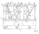
- the feeding rack 1 shown in figure 1 comprises in principle a lower girder 3 and an upper girder 4, in which a slideable operating rod and locking flaps 18 -at least one for each feeding opening- operated by said rod are accommodated.
- the lower girder 3 and the upper girder 4 are attached to column pipes which are not further indicated, said pipes being clamped with a lower portion in the concrete stable floor 2.
- the feeding rack 1 a number of feeding openings are realized, of which three are shown here. It is noted that the left feeding opening differs from the middle and right feeding opening. The latter two feeding openings belong to a so-called safety feeding rack, in which the tilting spike 7 can tilt through. Below this will be further gone into.
- Vertical spikes 5 and 6, as well as a buckled spike 8 extend between the lower girder 3 and the upper girder 4.
- the spikes 5 and 6 are attached to the upper girder 4 respectively lower girder 3, at their upper end by means of attachment plates 11 and at their lower end by means of attachment plates 12, for instance by welding.
- the buckled spike 8 is at its upper end attached also to attachment plate 11 and at its lower end to the lower girder 3.
- a bracket 34 is mounted, which bracket at its end carries a hinge pin 35, on which the hinge spike 7 is mounted.
- the feeding opening has a substantially V-shaped form, suitable to receive the head of a cow at the top, which cow after that can by moving head and neck downwards let the tilting spike turn in direction A, to the position indicated in figure 1 in the middle of the feeding rack.
- the tilting spike is substantially vertical, and it could be locked by means of the locking flap 18.
- the feeding opening then has a substantially rectangular form, in which the distance between the tilting spike 7 and the vertical spike 5 is smaller than the width of the head of the cow.
- FIG. 1 In the middle of figure 1 two types of buckled spikes are shown.
- the lower portion of the buckled spike of the left feeding opening is shown once more by striped lines.
- Tilting spike 8 suitable for a safety feeding rack is depicted with full lines.
- the upper portion of the tilting spike 8a is identical to the upper portion 8a of the left feeding opening.
- the lower portion 8c Contrary to the lower portion 8b in the left feeding place the lower portion 8c however also runs diverging to the vertical spike 6 to be mounted thereon, so that tilting spike 7 can slap further in direction B, at least if the locking flap 18 is put out of action.
- the situation shown in figure 1 on the right can be obtained, the so-called safety position, in which the cow could possibly withdraw her head from the lower portion of the now inverted U-shaped feeding opening.
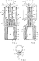
- the upper girder 4 is shown in a cut-away condition.
- the upper girder comprises a tubular profile, which forms an elongated slit at the lower side, through which the upper ends of the tilting spikes can swing.
- the cross-section thus is substantially inverted U-shaped. Shown are the upper wall 14, a side wall 15, a half of the bottom walls 16 and its slit bounding side edge 17.
- a flat operating rod 17 is accommodated, which is slideable and is supported on the other half of the bottom wall 16 which is not shown.
- the operating rod 70 is provided with a recess 27 at each feeding place, in which recess the locking part 25 of locking flap 18 can fall in order to enter the path of tilting spike 7. It will be understood that a recess can alternatively be formed by the area between two elevations on the operating rod which are each provided at the location of a feeding opening.
- a recess can alternatively be formed by the area between two elevations on the operating rod which are each provided at the location of a feeding opening.
- operating part 24 of the locking flap 18 On the other side of the hinge 23 operating part 24 of the locking flap 18 is situated, which operating part has a flat operating plane 26 (see figure 3).
- operating holes 22 are arranged at each feeding place, said holes allowing passage to a finger of a farmer.
- the operating part 24 is situated at an angle ⁇ , which differs from 180°, in relation to the locking part.
- ⁇ which differs from 180°
- the upper plane 26 of the operating part 4 is parallel to the upper wall 14, at a minimal distance therefrom.
- the finger of the farmer will quickly make contact with the plane 26, because of which the operating of locking flap 18 takes place in a reliable way.
- the locking flap which is preferably made of plastic, a striking colour, so that it will be immediately clear to the farmer where the operating hole for the locking flap is situated, in case several holes are arranged in the upper wall 14.
- the locking flap 18 is at the end of the locking part provided with a locking plane 56, which is at an angle ⁇ in relation to the main planes of the locking part 25, in which the angle ⁇ is equal to 90°- ⁇ .
- the end of the locking part 25 is furthermore provided with a supporting plane 57, which is perpendicular to the locking plane 56. With supporting plane 57 the locking flap rests on the boundaries of the recess 27 in the operating rod 70.
- locking flap 18' is shown which is similar to locking flap 18 but particularly suitable for so-called broad upper girders.
- Locking part 25' is at the bottom side provided with cams 58 integrally formed therewith, which have the effect that, if the operating rod is operated to move locking flap 18' out of the locking position, they shorten the necessary sliding stroke, because they constitute a lowering of the lower surface of the locking part and therefore quickly abut the as seen in figure 3 left boundary of recess 27.
- a cam 58 is provided on both sides, to keep a choice regarding the side of the tilting spike where the operating rod comes to lie in the broad upper girder.
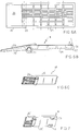
- the tilting spike 7 can be seen, which at the upper end is provided with a plastic cap 20 put onto it.
- This cap 20 has replaced the ordinary upper end of the round tilting spike 7, which tilting spike 7 is made of steel.
- the tilting spike 7 is kept shorter than usual for that reason, in the case of an old feeding rack the upper end of the tilting spike, which is usually flattened, may be sawed off.
- the plastic spike cap 20 consists substantially of a lower part 28 and an upper part 29.
- the lower part 28 serves to secure the spike cap 20 tightly, against axial movement and rotation, on the tilting spike.
- the lower part 28 comprises a roundgoing wall 37, which at the lower end has been made smaller, with an inner pilot edge 32 and an outer slanting wall 33, to prevent injuries.
- the roundgoing wall 37 is provided with vertical ribs 34, which form radially inwardly directed, axial clamping faces.
- a roundgoing wall 36 which with the roundgoing wall 37 determines a slit-shaped space 31, in which the upper end of the tilting spike 7 can be tightly accommodated.
- the roundgoing wall 36 determines an inner cavity 30, because of which the roundgoing wall 36 when putting up on the tilting spike 7 can evade a little to the inside should such be necessary.
- the roundgoing wall 37 is furthermore at least at one location, at a distance from the lower end provided with a recess, in which a snap tongue 35 with snap end 66 is situated.
- the snap end 66 can cooperate with a hole made in suitable place in tilting spike 7, so that after putting up the spike cap 20 on the tilting spike 7 the spike cap 20 is secured against rotation and sliding upwards.
- the lower part 28 is firmly connected to the upper part 29 by means of intermediate part 67, said upper part having a rectangular horizontal cross-section, as can be seen in figure 5A.
- the upper part 29 is designed hollow out of material saving and material processing considerations. Nevertheless it is pursued to design the upper part 29 as rigid as possible, which has been realized by the grid-shaped cross-section (see figure 2), with roundgoing wall 68 and intermediate walls 39 and 40.
- chambers 38 (six here) are defined, from the bottom of which the strengthening ribs 41 reach upwards.
- the rigid ribs 41 reach at least the level of the lower wall of the upper girder.
- the spike cap 20, in particular its upper part 29, unites no fewer than seven stop surfaces.
- a first stop surface 42 which can cooperate with locking surface 56 of locking flap 18.
- a second stop surface 43 is situated, which in a muffling way can abut the upper end of buckled spike 8a.
- the first stop surfaces 42 and the second stop surfaces 43 underneath them have sufficient length to form third engaging surfaces 47 which in a muffling way can be engaged by a pulling up flight which is not further shown, which flight can be accommodated in the upper girder 4 and in a manner known per se can be active to force the tilting spike 7 to tilt in the direction A.
- the roundgoing wall 68 and the intermediate walls 39 and 40 form fourth stop surfaces 44, which can cooperate with the lower surface of locking part 25 of locking flap 18, in a movement in the direction A (figure 1).
- fifth stop surfaces 45 On either side, as shown in figure 5, are fifth stop surfaces 45, which abut mufflingly against the edges 17 of the tubular profile of the upper girder 4.
- the upper part 29 of the spike cap 20 is provided with a sixth stop surface 46, which in the same way as the first stop surface 42 can cooperate with a locking flap, which in relation to locking flap 18 and tilting spike 7 is arranged in the upper girder 4 in a mirror symmetrical way, in case of a safety feeding rack, as shown in the middle and the right of figure 1.
- the fifth stop surface 46 can cooperate with a stop block fixedly fitted in the upper profile, which block is preferably made of plastic as well or another sound muffling material.
- the open upper side of the spike cap 20 makes it suitable to be locked by means of a stop pin 75 provided with an engaging and supporting thickening 76, which stop pin can be inserted in a hole 77 provided in the upper wall 14 of the upper girder 4 at the location of the feeding position and then in the open chambers of the spike cap 20 (see figures 4, 5). In this way the farmer can also notice immediately which tilting spikes are in the locked feeding position.
- the material of which the flap 18 and the cap 20 are made is sound muffling, wear-resistant and strong.
- a suitable material is polypropene, but other suitable plastics or suitable natural rubbers can also be appropriate.
- an additional muffler 19 is shown on the tilting spike 7.
- the lower part of the tilting spike 7 can abut against the lower part 8b of the buckled spike.
- rubber caps which are put into a hole in the tilting spike 7, are not granted a long life.
- the blind rivet has a head 61, a butt sleeve 62, a detaining plate 64 and a little rubber block vulcanized on it.
- the butt sleeve 62 When tightening the blind rivet, in particular its rod 60, the butt sleeve 62 deforms into the shape indicated with 62', after which the butt sleeve is fixedly locked on the tilting spike 7 between the deformed butt sleeve 62' and detaining plate 64. In that way the rubber block 63 is also firmly in its place.
- the rubber block can for instance be 4 to 15 mm thick.
Landscapes
- Life Sciences & Earth Sciences (AREA)
- Zoology (AREA)
- Environmental Sciences (AREA)
- Animal Husbandry (AREA)
- Biodiversity & Conservation Biology (AREA)
- Packaging Of Annular Or Rod-Shaped Articles, Wearing Apparel, Cassettes, Or The Like (AREA)
- Treatment Of Liquids With Adsorbents In General (AREA)
- Advancing Webs (AREA)
- Valve Device For Special Equipments (AREA)
- Eye Examination Apparatus (AREA)
- Liquid Crystal Substances (AREA)
- Floor Finish (AREA)
- Refuge Islands, Traffic Blockers, Or Guard Fence (AREA)
- Lock And Its Accessories (AREA)
- Catching Or Destruction (AREA)
Abstract
Description
Claims (15)
- Feeding rack with a lower girder and an upper girder, and a plurality of vertical parts connecting these girders to each other, comprising a plurality of substantially vertical spikes spaced at regular intervals, which each time bound one side of a feeding place, which feeding places are bounded on the other side by means of a tilting spike which is mounted in the feeding rack in a tiltable manner in order to be able to tilt between a first position, in which the tilting pipe is slanting and the feeding opening forms a substantially V-shaped passage, and at least one second position, in which the tilting spike is substantially vertical, at least one locking means for all the tilting spikes being arranged in the upper girder, the feeding rack being provided with a operating rod, which extends parallel to the plane of the feeding rack and is provided with means for operating the locking means, each locking means being accommodated within the upper girder and provided with locking surfaces for the upper end of the tilting spike which locking surfaces are facing away from the first position, the swinging path of said upper end being at least partly within the upper girder, the upper end comprising first stop surfaces, which cooperate with the locking surfaces and are made of sound muffling material, such as plastic.
- Feeding rack according to claim 1, in which the upper end comprises second stop surfaces, which are arranged -and preferably protrude radially from the rest of the tilting spike- such to be able to abut against the fixed spikes in the feeding rack in the first position, and which are made of sound muffling material such as plastic.
- Feeding rack according to claim 1, in which the feeding rack is furthermore provided with a slideable auxiliary operating rod, which is provided with flights situated within the upper girder for pulling up the tilting spike, which flight is provided with surfaces which cooperate with third stop surfaces formed by the first and/or second stop surfaces, and located on the upper end of the tilting spikes for having the tilting spike tilted in a direction towards the second or a further tilted position when sliding the auxiliary operating rod, the third stop surfaces being made of sound muffling material, such as plastic, the third stop surfaces preferably extending in the longitudinal direction of the tilting spike at a location and along a length which coincides with the path of movement of the flight surfaces over the upper end of the tilting spike.
- Feeding rack according to any one of the preceding claims, in which the upper end comprises fourth stop surfaces, which are facing upwards and located such that the locking means project in the swinging path thereof so that the upper end can lift the locking means in a movement from the first position to the second position, the fourth stop surfaces being made of sound muffling material, such as plastic.
- Feeding rack according to any one of the preceding claims, the upper end of each tilting spike comprising sides situated on either side, which form fifth stop surfaces, of which the normal is substantially perpendicular to the plane of the feeding rack and which are made of sound muffling material, such as plastic.
- Feeding rack according to any one of the preceding claims, the upper girder being provided with a further locking means for detaining the tilting spike from tilting from the second position to a further tilting, safety position, the further locking means being accommodated within the upper girder and provided with locking surfaces for the upper end of the tilting spike which locking surfaces are facing the first position, the swinging path of said upper end being at least within the upper girder, the upper end of the tilting spike comprising sixth stop surfaces, which cooperate with the locking surfaces of the further locking means and are made of sound muffling material, such as plastic.
- Feeding rack according to any one of the preceding claims, the upper end comprising seventh stop surfaces, which are arranged -and preferably protrude radially from the rest of the tilting spike- such to be able to abut against the fixed spikes of the feeding rack in a position further than the second tilted safety position, and which are made of sound muffling material, such as plastic.
- Feeding rack according to any one of the preceding claims, in which the upper end of the tilting spike has a roundgoing surface of plastic material, which contains the first, second, third, fifth, sixth and/or seventh stop surfaces.
- Feeding rack according to claim 8, in which the roundgoing surface forms a whole with an upper plane of sound muffling material, such as plastic, which forms the fourth stop surfaces.
- Feeding rack according to claim 9, in which the upper end is formed like a cap of sound muffling material, such as plastic, which is mounted on a metal tilting spike, which plastic cap preferably has a lower part which is slid in a clamping manner on the pipe-shaped tilting spike and an upper part which forms a whole with it and forms the roundgoing surface, and in which preferably the lower part of the cap is provided with a snap finger, which fits into a snap opening arranged in the tilting spike.
- Cap of sound muffling material with a lower end which is provided with means for attachment on the upper end of a tilting spike of a feeding rack.
- Feeding rack according to any one of the preceding claims, in which the locking means is formed by a locking flap, which is arranged in the upper girder to be pivotable about a horizontal hinge axis and has a locking part situated on the one side of the hinge axis and an operating part on the other side of the hinge axis, the upper girder having a horizontal upper wall in which at the location of the operating parts of the locking flaps finger operating holes are arranged, the hinge axis being situated near the upper wall and the operating part extending substantially horizontal when the locking flap is in the locking position, the locking flaps being preferably made of sound muffling material such as plastic.
- Feeding rack according to any one of the preceding claims, in which the tilting spike is provided with one or a plurality of muffling means, which are formed by a blind rivet mounted in a hole in the tilting spike, on the detaining plate of which a body of sound muffling material is attached, the sound muffling material preferably being rubber, which is attached on the detaining plate, for instance by vulcanization.
- Feeding rack according to claim 13, in which the muffling means is situated on the side of the tilting spike which faces away from the feeding place, the fastening means preferably being provided in the portion of the tilting spike which is situated below the tilting point of the tilting spike.
- Blind rivet, of which the detaining plate on the pull side is provided with muffling material attached on it, preferably rubber vulcanized on it.
Applications Claiming Priority (2)
| Application Number | Priority Date | Filing Date | Title |
|---|---|---|---|
| NL1004436A NL1004436C2 (en) | 1996-11-05 | 1996-11-05 | Feeding fence. |
| NL1004436 | 1996-11-05 |
Publications (3)
| Publication Number | Publication Date |
|---|---|
| EP0845206A2 true EP0845206A2 (en) | 1998-06-03 |
| EP0845206A3 EP0845206A3 (en) | 1998-09-30 |
| EP0845206B1 EP0845206B1 (en) | 2003-04-16 |
Family
ID=19763801
Family Applications (1)
| Application Number | Title | Priority Date | Filing Date |
|---|---|---|---|
| EP97203382A Expired - Lifetime EP0845206B1 (en) | 1996-11-05 | 1997-11-04 | Feeding rack |
Country Status (5)
| Country | Link |
|---|---|
| EP (1) | EP0845206B1 (en) |
| AT (1) | ATE237222T1 (en) |
| DE (1) | DE69720921T2 (en) |
| DK (1) | DK0845206T3 (en) |
| NL (1) | NL1004436C2 (en) |
Cited By (4)
| Publication number | Priority date | Publication date | Assignee | Title |
|---|---|---|---|---|
| FR2812172A1 (en) * | 2000-07-31 | 2002-02-01 | Jose Fornes | Rocking bar for livestock feed trough access frame has forked upper end fitted with detachable noise-damping block of elastic material |
| FR2943214A1 (en) * | 2009-03-19 | 2010-09-24 | Jose Fornes | Soundproof blocking part for use on pivoting rocker arm of feed rack, has fixing part set on rocker arm and connected to internal side face of protuberance forming part by connection part located towards external axial end of blocking part |
| EP2737793A1 (en) * | 2010-11-12 | 2014-06-04 | GEA Farm Technologies GmbH | Self-locking feed fence |
| KR20190033305A (en) * | 2017-09-21 | 2019-03-29 | 안광덕 | Tilting feeder |
Families Citing this family (1)
| Publication number | Priority date | Publication date | Assignee | Title |
|---|---|---|---|---|
| NL1006961C2 (en) | 1997-09-05 | 1999-03-08 | Sgt Exploitatie Mij | A method of cutting a glass guide, such as a gas chromatography column, a glass fiber and the like, and apparatus for carrying out this method. |
Citations (1)
| Publication number | Priority date | Publication date | Assignee | Title |
|---|---|---|---|---|
| EP0562679A1 (en) | 1992-03-27 | 1993-09-29 | Koninklijke Philips Electronics N.V. | Low pressure discharge lamp and luminaire provided with such a lamp |
Family Cites Families (10)
| Publication number | Priority date | Publication date | Assignee | Title |
|---|---|---|---|---|
| AU476213B2 (en) * | 1972-10-06 | 1974-04-11 | Takahashi, Junji | Plastic rivet |
| NL8101854A (en) * | 1981-04-15 | 1982-11-01 | Boer G Erven Bv De | FEEDING GARDEN FOR STABLES. |
| DE3439451A1 (en) * | 1983-11-09 | 1985-05-15 | Sonntag GmbH, 8945 Legau | Device on self-locking gates for cattle |
| NL99828C (en) * | 1984-01-20 | |||
| US4826378A (en) * | 1985-07-22 | 1989-05-02 | R B & W Corporation | Sealing cap tubular rivet head and assembly |
| NL8703045A (en) * | 1987-12-16 | 1989-07-17 | Spinder Stalinrichting Bv | FEEDING GATE. |
| NL9200561A (en) * | 1992-03-26 | 1993-10-18 | Boer Stalinrichtingen | ATTACHMENT ATTACHMENT AND METHOD FOR MAKING THEREOF |
| DE4216620C2 (en) * | 1992-05-20 | 1998-04-09 | Wilhelm Kristen | Self-catching feed fence |
| NL194385C (en) * | 1993-08-26 | 2002-03-04 | Johannes Martinus Willibrordus | Self-catching mainly vertically arranged feed fence for cattle. |
| GB9519474D0 (en) * | 1995-09-23 | 1995-11-22 | Emhart Inc | Improved blind rivet |
-
1996
- 1996-11-05 NL NL1004436A patent/NL1004436C2/en not_active IP Right Cessation
-
1997
- 1997-11-04 AT AT97203382T patent/ATE237222T1/en not_active IP Right Cessation
- 1997-11-04 DK DK97203382T patent/DK0845206T3/en active
- 1997-11-04 EP EP97203382A patent/EP0845206B1/en not_active Expired - Lifetime
- 1997-11-04 DE DE69720921T patent/DE69720921T2/en not_active Expired - Lifetime
Patent Citations (1)
| Publication number | Priority date | Publication date | Assignee | Title |
|---|---|---|---|---|
| EP0562679A1 (en) | 1992-03-27 | 1993-09-29 | Koninklijke Philips Electronics N.V. | Low pressure discharge lamp and luminaire provided with such a lamp |
Cited By (4)
| Publication number | Priority date | Publication date | Assignee | Title |
|---|---|---|---|---|
| FR2812172A1 (en) * | 2000-07-31 | 2002-02-01 | Jose Fornes | Rocking bar for livestock feed trough access frame has forked upper end fitted with detachable noise-damping block of elastic material |
| FR2943214A1 (en) * | 2009-03-19 | 2010-09-24 | Jose Fornes | Soundproof blocking part for use on pivoting rocker arm of feed rack, has fixing part set on rocker arm and connected to internal side face of protuberance forming part by connection part located towards external axial end of blocking part |
| EP2737793A1 (en) * | 2010-11-12 | 2014-06-04 | GEA Farm Technologies GmbH | Self-locking feed fence |
| KR20190033305A (en) * | 2017-09-21 | 2019-03-29 | 안광덕 | Tilting feeder |
Also Published As
| Publication number | Publication date |
|---|---|
| DE69720921T2 (en) | 2004-02-12 |
| EP0845206A3 (en) | 1998-09-30 |
| DK0845206T3 (en) | 2003-08-04 |
| ATE237222T1 (en) | 2003-05-15 |
| NL1004436C2 (en) | 1998-05-08 |
| EP0845206B1 (en) | 2003-04-16 |
| DE69720921D1 (en) | 2003-05-22 |
Similar Documents
| Publication | Publication Date | Title |
|---|---|---|
| US6027276A (en) | Scaffolding node | |
| EP1408174B1 (en) | Gutter shield for eaves trough | |
| NL2024136B1 (en) | Roof hook | |
| US4065824A (en) | Lip extender for loading dock levelers | |
| EP0845206A2 (en) | Feeding rack | |
| US8851559B2 (en) | Lid-fastening structure | |
| US7546711B2 (en) | Explosion-resisting window | |
| US20010016145A1 (en) | Mounting for jumps | |
| CN101395326A (en) | Refuse chute | |
| AU719821B2 (en) | Pivot bracket | |
| EP0925205B1 (en) | A railing bracket | |
| US4238895A (en) | Lift arm with improved chain connector | |
| EP1117593B1 (en) | Lid assembly including pivotally-attached lid prop member | |
| CA3197865A1 (en) | Dock leveler with deck hinge | |
| KR102049470B1 (en) | Safety net installation device for building | |
| EP2550417B1 (en) | Construction safety screen | |
| US4817291A (en) | Motor-driven chain saw having an improved handle | |
| HU202022B (en) | Snow plough | |
| FI12035U1 (en) | Mounting arrangements for attaching handrails and handrails | |
| KR102287028B1 (en) | Guide rail | |
| US7188646B2 (en) | Kit to form a wood splitting apparatus | |
| US5599049A (en) | Locking member | |
| EP1555362B1 (en) | Holding device for railing posts on transverse arm of a wall scaffold or a ladder bracket | |
| JP4047600B2 (en) | Home fall prevention fence | |
| JP2007001726A (en) | Installing tool of elevator |
Legal Events
| Date | Code | Title | Description |
|---|---|---|---|
| PUAI | Public reference made under article 153(3) epc to a published international application that has entered the european phase |
Free format text: ORIGINAL CODE: 0009012 |
|
| AK | Designated contracting states |
Kind code of ref document: A2 Designated state(s): AT BE CH DE DK ES FR GB IE IT LI LU NL PT SE |
|
| AX | Request for extension of the european patent |
Free format text: AL;LT;LV;RO;SI |
|
| 17P | Request for examination filed |
Effective date: 19980506 |
|
| PUAL | Search report despatched |
Free format text: ORIGINAL CODE: 0009013 |
|
| AK | Designated contracting states |
Kind code of ref document: A3 Designated state(s): AT BE CH DE DK ES FI FR GB GR IE IT LI LU MC NL PT SE |
|
| AX | Request for extension of the european patent |
Free format text: AL;LT;LV;RO;SI |
|
| RAP1 | Party data changed (applicant data changed or rights of an application transferred) |
Owner name: REDNIPS HOLDING B.V. |
|
| AKX | Designation fees paid |
Free format text: AT BE CH DE DK ES FR GB IE IT LI LU NL PT SE |
|
| RIN1 | Information on inventor provided before grant (corrected) |
Inventor name: STUNNEBRINK, MARCO DIMPHINA HENRICUS Inventor name: RIKHOF, JOHANNES HENDRIKUS Inventor name: TIMMERMANS, HUBERTUS RENIER MARIA |
|
| 17Q | First examination report despatched |
Effective date: 20010321 |
|
| GRAH | Despatch of communication of intention to grant a patent |
Free format text: ORIGINAL CODE: EPIDOS IGRA |
|
| GRAH | Despatch of communication of intention to grant a patent |
Free format text: ORIGINAL CODE: EPIDOS IGRA |
|
| GRAA | (expected) grant |
Free format text: ORIGINAL CODE: 0009210 |
|
| AK | Designated contracting states |
Designated state(s): AT BE CH DE DK ES FR GB IE IT LI LU NL PT SE |
|
| PG25 | Lapsed in a contracting state [announced via postgrant information from national office to epo] |
Ref country code: LI Free format text: LAPSE BECAUSE OF FAILURE TO SUBMIT A TRANSLATION OF THE DESCRIPTION OR TO PAY THE FEE WITHIN THE PRESCRIBED TIME-LIMIT Effective date: 20030416 Ref country code: IT Free format text: LAPSE BECAUSE OF FAILURE TO SUBMIT A TRANSLATION OF THE DESCRIPTION OR TO PAY THE FEE WITHIN THE PRE;WARNING: LAPSES OF ITALIAN PATENTS WITH EFFECTIVE DATE BEFORE 2007 MAY HAVE OCCURRED AT ANY TIME BEFORE 2007. THE CORRECT EFFECTIVE DATE MAY BE DIFFERENT FROM THE ONE RECORDED.SCRIBED TIME-LIMIT Effective date: 20030416 Ref country code: FR Free format text: LAPSE BECAUSE OF FAILURE TO SUBMIT A TRANSLATION OF THE DESCRIPTION OR TO PAY THE FEE WITHIN THE PRESCRIBED TIME-LIMIT Effective date: 20030416 Ref country code: CH Free format text: LAPSE BECAUSE OF FAILURE TO SUBMIT A TRANSLATION OF THE DESCRIPTION OR TO PAY THE FEE WITHIN THE PRESCRIBED TIME-LIMIT Effective date: 20030416 Ref country code: BE Free format text: LAPSE BECAUSE OF FAILURE TO SUBMIT A TRANSLATION OF THE DESCRIPTION OR TO PAY THE FEE WITHIN THE PRESCRIBED TIME-LIMIT Effective date: 20030416 Ref country code: AT Free format text: LAPSE BECAUSE OF FAILURE TO SUBMIT A TRANSLATION OF THE DESCRIPTION OR TO PAY THE FEE WITHIN THE PRESCRIBED TIME-LIMIT Effective date: 20030416 |
|
| REG | Reference to a national code |
Ref country code: GB Ref legal event code: FG4D |
|
| REG | Reference to a national code |
Ref country code: CH Ref legal event code: EP |
|
| REF | Corresponds to: |
Ref document number: 69720921 Country of ref document: DE Date of ref document: 20030522 Kind code of ref document: P |
|
| REG | Reference to a national code |
Ref country code: IE Ref legal event code: FG4D |
|
| PG25 | Lapsed in a contracting state [announced via postgrant information from national office to epo] |
Ref country code: SE Free format text: LAPSE BECAUSE OF FAILURE TO SUBMIT A TRANSLATION OF THE DESCRIPTION OR TO PAY THE FEE WITHIN THE PRESCRIBED TIME-LIMIT Effective date: 20030716 Ref country code: PT Free format text: LAPSE BECAUSE OF FAILURE TO SUBMIT A TRANSLATION OF THE DESCRIPTION OR TO PAY THE FEE WITHIN THE PRESCRIBED TIME-LIMIT Effective date: 20030716 |
|
| REG | Reference to a national code |
Ref country code: DK Ref legal event code: T3 |
|
| PG25 | Lapsed in a contracting state [announced via postgrant information from national office to epo] |
Ref country code: ES Free format text: LAPSE BECAUSE OF FAILURE TO SUBMIT A TRANSLATION OF THE DESCRIPTION OR TO PAY THE FEE WITHIN THE PRESCRIBED TIME-LIMIT Effective date: 20031030 |
|
| REG | Reference to a national code |
Ref country code: CH Ref legal event code: PL |
|
| PG25 | Lapsed in a contracting state [announced via postgrant information from national office to epo] |
Ref country code: LU Free format text: LAPSE BECAUSE OF NON-PAYMENT OF DUE FEES Effective date: 20031104 Ref country code: IE Free format text: LAPSE BECAUSE OF NON-PAYMENT OF DUE FEES Effective date: 20031104 |
|
| PLBE | No opposition filed within time limit |
Free format text: ORIGINAL CODE: 0009261 |
|
| STAA | Information on the status of an ep patent application or granted ep patent |
Free format text: STATUS: NO OPPOSITION FILED WITHIN TIME LIMIT |
|
| 26N | No opposition filed |
Effective date: 20040119 |
|
| EN | Fr: translation not filed | ||
| REG | Reference to a national code |
Ref country code: IE Ref legal event code: MM4A |
|
| PGFP | Annual fee paid to national office [announced via postgrant information from national office to epo] |
Ref country code: DK Payment date: 20091109 Year of fee payment: 13 |
|
| PGFP | Annual fee paid to national office [announced via postgrant information from national office to epo] |
Ref country code: NL Payment date: 20091127 Year of fee payment: 13 |
|
| PGFP | Annual fee paid to national office [announced via postgrant information from national office to epo] |
Ref country code: GB Payment date: 20091104 Year of fee payment: 13 |
|
| PGFP | Annual fee paid to national office [announced via postgrant information from national office to epo] |
Ref country code: DE Payment date: 20091223 Year of fee payment: 13 |
|
| REG | Reference to a national code |
Ref country code: NL Ref legal event code: V1 Effective date: 20110601 |
|
| REG | Reference to a national code |
Ref country code: DK Ref legal event code: EBP |
|
| GBPC | Gb: european patent ceased through non-payment of renewal fee |
Effective date: 20101104 |
|
| REG | Reference to a national code |
Ref country code: DE Ref legal event code: R119 Ref document number: 69720921 Country of ref document: DE Effective date: 20110601 Ref country code: DE Ref legal event code: R119 Ref document number: 69720921 Country of ref document: DE Effective date: 20110531 |
|
| PG25 | Lapsed in a contracting state [announced via postgrant information from national office to epo] |
Ref country code: NL Free format text: LAPSE BECAUSE OF NON-PAYMENT OF DUE FEES Effective date: 20110601 |
|
| PG25 | Lapsed in a contracting state [announced via postgrant information from national office to epo] |
Ref country code: DE Free format text: LAPSE BECAUSE OF NON-PAYMENT OF DUE FEES Effective date: 20110531 |
|
| PG25 | Lapsed in a contracting state [announced via postgrant information from national office to epo] |
Ref country code: DK Free format text: LAPSE BECAUSE OF NON-PAYMENT OF DUE FEES Effective date: 20101130 |
|
| PG25 | Lapsed in a contracting state [announced via postgrant information from national office to epo] |
Ref country code: GB Free format text: LAPSE BECAUSE OF NON-PAYMENT OF DUE FEES Effective date: 20101104 |