EP0844472B1 - Vorrichtung zur Fehlerdetektion in einer optischen Faser - Google Patents
Vorrichtung zur Fehlerdetektion in einer optischen Faser Download PDFInfo
- Publication number
- EP0844472B1 EP0844472B1 EP19970402711 EP97402711A EP0844472B1 EP 0844472 B1 EP0844472 B1 EP 0844472B1 EP 19970402711 EP19970402711 EP 19970402711 EP 97402711 A EP97402711 A EP 97402711A EP 0844472 B1 EP0844472 B1 EP 0844472B1
- Authority
- EP
- European Patent Office
- Prior art keywords
- opticfiber
- laser beam
- detection means
- fiber
- light beam
- Prior art date
- Legal status (The legal status is an assumption and is not a legal conclusion. Google has not performed a legal analysis and makes no representation as to the accuracy of the status listed.)
- Expired - Lifetime
Links
- 239000013307 optical fiber Substances 0.000 title description 10
- 238000001514 detection method Methods 0.000 claims description 21
- 230000005540 biological transmission Effects 0.000 claims description 16
- 238000001228 spectrum Methods 0.000 claims description 10
- 230000007547 defect Effects 0.000 claims description 6
- 230000003287 optical effect Effects 0.000 claims description 5
- 239000012141 concentrate Substances 0.000 claims description 3
- 239000000835 fiber Substances 0.000 description 60
- 239000011248 coating agent Substances 0.000 description 4
- 238000000576 coating method Methods 0.000 description 4
- 230000015556 catabolic process Effects 0.000 description 2
- 238000006731 degradation reaction Methods 0.000 description 2
- 239000000463 material Substances 0.000 description 2
- 208000032370 Secondary transmission Diseases 0.000 description 1
- 230000006978 adaptation Effects 0.000 description 1
- 238000002592 echocardiography Methods 0.000 description 1
- 230000000694 effects Effects 0.000 description 1
- 230000005284 excitation Effects 0.000 description 1
- 238000005259 measurement Methods 0.000 description 1
- 238000005457 optimization Methods 0.000 description 1
- 230000005693 optoelectronics Effects 0.000 description 1
- 238000002310 reflectometry Methods 0.000 description 1
- 230000035945 sensitivity Effects 0.000 description 1
- 238000011144 upstream manufacturing Methods 0.000 description 1
- 238000001429 visible spectrum Methods 0.000 description 1
Images


Classifications
-
- G—PHYSICS
- G01—MEASURING; TESTING
- G01M—TESTING STATIC OR DYNAMIC BALANCE OF MACHINES OR STRUCTURES; TESTING OF STRUCTURES OR APPARATUS, NOT OTHERWISE PROVIDED FOR
- G01M11/00—Testing of optical apparatus; Testing structures by optical methods not otherwise provided for
- G01M11/30—Testing of optical devices, constituted by fibre optics or optical waveguides
- G01M11/33—Testing of optical devices, constituted by fibre optics or optical waveguides with a light emitter being disposed at one fibre or waveguide end-face, and a light receiver at the other end-face
Definitions
- the present invention relates to a device for detecting a damage in an optical fiber.
- optical fibers conveying pulsed or continuous laser beams, whose energy varies from a few mJ to several tens of J, and the power from a few mW to several kW.
- Certain optical fibers are used to convey laser energy in a flexible manner over relatively large distances.
- an optical fiber is characterized by several parameters such as its diameter, its length, its numerical aperture, the material constituting its core, or the state of its input and output faces.
- the beam laser that we want to convey by this optical fiber is characterized by its wavelength, its power for a continuous emission laser, its energy and its pulse duration for a pulse laser, the adaptation of the laser beam for inject it into the fiber, etc.
- the beam crosses the fiber without damaging it, as long as the damage threshold of the fiber is respected, that is to say the power density or d maximum energy admissible by the interior of the fiber, as well as by its entry and exit faces.
- the damage threshold of the fiber is lowered.
- the fiber is then damaged by the passage of the laser beam and losses which can be very significant appear in the degraded transmission of the laser beam. In applications using high power or high energy lasers, this degradation can cause the fiber to break due to the energy of the transmitted laser beam.
- US Pat. No. 4,385,832 describes a detection device making apply a reflective coating deposited on the emitting face of the fiber optics and an optoelectronic assembly to detect the intensity of the beam reflected by this coating, at the receiving face of the fiber.
- This device makes it possible to detect a break in the fiber thanks to the variation intensity of the reflected ray due to the fact that the reflectivity of the section cut is different from that of the emitting side of the fiber which carries this coating
- This solution has the disadvantages of having to have a reflective coating on the emitting side of the fiber and not to detect damage that does not cause reflection.
- Japanese patent application No. 56164936 describes a device for detecting a defect in an optical fiber consisting in emitting in the fiber of the light pulses and to detect the echoes reflected by the defect so as to determine the position of the defect along the fiber. It is a relatively complex device that requires transmission of light pulses involving an interruption of operation normal fiber.
- the present invention aims to eliminate these drawbacks. To this end, it is based on the observation that when the energy or power density of the laser exceeds the damage threshold of a place of the fiber, it occurs under the effect of the laser beam passing through the fiber a damage accompanied by a point luminous which emits in all directions and in a broad spectrum, especially in the visible spectrum, this bright spot being the consequence of the excitation of the atoms being there.
- It offers a device for detecting damage in a fiber optics used for the transmission of a laser beam emitted by a source laser, this device involving application means on the face input of the fiber of a laser beam having a spectrum of lengths waveform and detection means capable of detecting a beam light caused by damage to the fiber.
- this device is characterized in that the detection means are designed to detect at any end of the fiber the emission of a light point occurring on the fiber at a place where the energy or power density of the laser exceeds a damage threshold, these detection means therefore being selectively sensitive to waves luminous located outside the above spectrum so as to avoid any interference with the beam transmitted in the fiber by the means application.
- the device comprises means for transmission and focusing to collect light from a damage of the fiber and transmitted by it at one end, and for send it to the detection means.
- the light point generated by the damage emits light in a broad spectrum
- a bandpass filter interposed on the path of the light beam applied at the input of the means of detection, which lets pass a frequency spectrum outside that of the laser beam to be transmitted by the fiber.
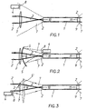
- FIG. 1 represents an optical fiber 1 which transmits a laser beam focused in a known manner by a lens 3 and applied to the input face 10 of the fiber 1.
- a detector 4 To detect an anomaly in the fiber, a detector 4 has been placed which picks up part of the light beam 7 transmitted to the input face 10 of the fiber 1 and emitted by a possible damaged point of the fiber. In this way, part of the light rays generated in the fiber due to the presence of localized damage, and which are sent by the fiber 1 to the input face 10, are applied to the input of the detector 4.
- the detector 4 can for example consist of a cell device photoelectrics that deliver an electrical signal when subjected to a light intensity.
- a end of the fiber for example at the input, a means of transmission and focusing which concentrates the rays returned by the fiber to focus them towards detector input 4.
- these transmission and focusing means consist of a converging reflector 5, advantageously provided with a hole 6 for let the incident laser beam pass 2.
- a reflector 5 having undergone a dichroic treatment so that it transmits the incident laser beam 2 and that it reflects the light beam 7.
- the entire light beam 7 is transmitted and focused to the input of the detector 4.
- the means of transmission and focusing can be constituted by a lens device 5 'ensuring the convergence in the direction of detector 4, of the light beam generated by the damaged point and transmitted to the input face 10 of the fiber 1, this device lenses also being provided with a hole 6 ′ for passing the laser beam 2.
- the transmission and focusing means may also be constituted by a blade with parallel faces 12 having undergone a dichroic treatment so as to be transparent with respect to the laser beam 2, and to reflect the light beam 7. After reflection on the plate 12, the beam light 7 can be focused towards the input of detector 4 by a lens convergent 13.
- This variant embodiment of the invention also makes it possible to transmit and focus the entire light beam 7 towards the entrance of the detector 4.
- the concept of the invention is not modified if, instead of having the detector 4 and, where appropriate, the transmission and focusing means 5, 5 ', 12 and 13 on the side of the input face 10 of the fiber 1, they are arranged, as shown in Figures 4 to 6 and 8, on the side of the outlet face 11, the beam luminous resulting from the damage localized in the fiber being transmitted by this one, both towards its entry face 10 and towards its exit face 11.
- the efficiency of detection can be further improved by placing upstream of the input of the detector 4 an optical component 8, such as a filter device, for choose the range of wavelengths you want to observe in the beam bright that appears at the entrance or exit of fiber 1, and in particular for remove the wavelength range from the laser beam 2.
- an optical component 8 such as a filter device
- a filter device 9 which lets through only the frequency spectrum of laser beam 2 and another range of frequencies if necessary.
Landscapes
- Physics & Mathematics (AREA)
- Optics & Photonics (AREA)
- Chemical & Material Sciences (AREA)
- Analytical Chemistry (AREA)
- General Physics & Mathematics (AREA)
- Lasers (AREA)
- Testing Of Optical Devices Or Fibers (AREA)
Claims (11)
- Vorrichtung für die Feststellung eines Schadens in einem Lichtwellenleiter (1), der für die Übertragung eines Laserstrahls (2) verwendet wird, wobei diese Vorrichtung Mittel verwendet, um an die Eingangsseite des Lichtwellenleiters einen Laserstrahl anzulegen, der ein bestimmtes Wellenlängenspektrum aufweist, und Ortungseinrichtungen, die in der Lage sind, einen Lichtstrahl zu orten, der durch einen Schaden am Lichtwellenleiter hervorgerufen wird, dadurch gekennzeichnet, dass die Ortungseinrichtungen so konzipiert sind, dass sie an jedem beliebigen Ende des Lichtwellenleiters die Absendung eines Lichtpunkts orten, der am Lichtwellenleiter an einer Stelle erzeugt wird, an dem die Energiedichte oder die Leistung des Lasers eine Schadensschwelle übersteigt, wobei diese Ortungseinrichtungen infolgedessen für Lichtwellen sensibel sind, die außerhalb des genannten Spektrums liegen, um jede Interferenz mit dem Lichtstrahl zu vermeiden, der im Lichtwellenleiter anhand der Mittel für das Anlegen des Laserstrahls erzeugt wird.
- Vorrichtung gemäß Patentanspruch 1,
dadurch gekennzeichnet, dass sie Mittel für die Übertragung und Fokalisierung (5, 5') beinhaltet, um den Lichtstrahl (7), der von Lichtwellenleiter (1) übertragen wird, in Richtung auf eines der Enden (10, 11) des Lichtwellenleiters (1) zu sammeln und um ihn in Richtung der Ortungseinrichtungen (4) zu übermitteln. - Vorrichtung gemäß Patentanspruch 2,
dadurch gekennzeichnet, dass die Übertragungs- und Fokalisierungsmittel (5, 5') einen konkaven Reflektor (5) beinhalten, der den Lichtstrahl (7), der von einem der Enden (10, 11) des Lichtwellenleiters (1) stammt, zu konzentrieren und in Richtung auf den Eingang der Ortungsmittel (4) zu orientieren. - Vorrichtung gemäß Patentanspruch 2,
dadurch gekennzeichnet, dass die Übertragungs- und Fokalisierungsmittel (5, 5') eine Vorrichtung mit konvergenten Linsen (5') beinhalten, die den Lichtstrahl (7), der von einem der Enden (10, 11) des Lichtwellenleiters (1) stammt, konzentriert und in Richtung auf den Eingang der Ortungsmittel (4) orientiert. - Vorrichtung gemäß Patentanspruch 2,
dadurch gekennzeichnet, dass die Übertragungs- und Fokalisierungsmittel (5, 5') eine dünne Lamelle (12) mit parallelen Seiten beinhalten, die eine dichroitische Behandlung erhalten haben, um den Laserstrahl (29) zu übertragen und den Lichtstrahl (7), der von einem der Enden (10, 11) des Lichtwellenleiters (1) stammt, über eine Vorrichtung mit konvergenten Linsen (13), die den Lichtstrahl (7) fokalisiert, in Richtung auf die Ortungseinrichtungen (4) zu reflektieren. - Vorrichtung gemäß einem der Patentansprüche 2 bis 4,
dadurch gekennzeichnet, dass die Übertragungs- und Fokalisierungsmittel mit einer Bohrung (6, 6') versehen sind, die den Laserstrahl (2), der an die Eingangsseite (10) angelegt worden ist oder von der Ausgangsseite (11) des Lichtwellenleiters (1) stammt, passieren lässt. - Vorrichtung gemäß Patentanspruch 3,
dadurch gekennzeichnet, dass der Reflektor (5) einer dichroitischen Behandlung unterzogen worden ist, um den Lichtstrahl (7) zu reflektieren und den Laserstrahl (2) zu übertragen. - Vorrichtung gemäß einem der vorangegangenen Patentansprüche,
dadurch gekennzeichnet, das die Ortungseinrichtungen einen optischen Bandpassfilter (8) beinhalten, der auf dem Weg des Lichtstrahls (7) angeordnet ist, der an den Eingang eines Sensors (4) angelegt wird und mindestens einen Teil des Spektrums der Wellenlängen des Lichtstrahls (7) passieren lässt, mit Ausnahme des Spektrums der Wellenlänge des Laserstrahls (2), der über den Lichtwellenleiter (1) übertragen wird. - Vorrichtung gemäß einem der vorangegangenen Patentansprüche,
dadurch gekennzeichnet, dass er einen optischen Bandpassfilter (9) beinhaltet, der hinter dem Ausgang des Lichtwellenleiters (1) auf dem Weg des Laserstrahls (2) angeordnet ist und der das Spektrum der Wellenlängen des Laserstrahls (2) passieren lässt, der über den Lichtwellenleiter (1) übertragen wird und eventuell einen weiteren Wellenlängenbereich. - Vorrichtung gemäß einem der vorangegangenen Patentansprüche,
dadurch gekennzeichnet, dass die Ortungseinrichtungen ein Ausgangssignal abgeben, das an den Eingang der Steuerungsmittel der Quelle des Laserstrahls (2) angelegt wird, um dessen Eintreffen an der Eingangsseite (10) zu unterbrechen, sobald sie einen Schaden im Lichtwellenleiter (1) geortet haben. - Vorrichtung gemäß einem der Patentansprüche 2 bis 10,
dadurch gekennzeichnet, dass der Sensor (4) aus einer Vorrichtung mit fotosensorischen Zellen besteht, die ein elektrisches Ausgangssignal abgeben, wenn sie dem Licht ausgesetzt sind.
Applications Claiming Priority (2)
| Application Number | Priority Date | Filing Date | Title |
|---|---|---|---|
| FR9614353 | 1996-11-21 | ||
| FR9614353A FR2756053B1 (fr) | 1996-11-21 | 1996-11-21 | Dispositif de detection de dommage dans une fibre optique |
Publications (2)
| Publication Number | Publication Date |
|---|---|
| EP0844472A1 EP0844472A1 (de) | 1998-05-27 |
| EP0844472B1 true EP0844472B1 (de) | 2003-04-16 |
Family
ID=9497955
Family Applications (1)
| Application Number | Title | Priority Date | Filing Date |
|---|---|---|---|
| EP19970402711 Expired - Lifetime EP0844472B1 (de) | 1996-11-21 | 1997-11-13 | Vorrichtung zur Fehlerdetektion in einer optischen Faser |
Country Status (3)
| Country | Link |
|---|---|
| EP (1) | EP0844472B1 (de) |
| DE (1) | DE69720919D1 (de) |
| FR (1) | FR2756053B1 (de) |
Cited By (1)
| Publication number | Priority date | Publication date | Assignee | Title |
|---|---|---|---|---|
| US7088437B2 (en) | 2001-08-15 | 2006-08-08 | Optoskand Ab | Optical fibre means |
Families Citing this family (6)
| Publication number | Priority date | Publication date | Assignee | Title |
|---|---|---|---|---|
| JP5672729B2 (ja) * | 2010-03-15 | 2015-02-18 | 富士通株式会社 | 光伝送装置、レーザーモジュール、レーザーモジュールの故障検出方法及びレーザーモジュールの故障検出プログラム |
| CN108195570A (zh) * | 2017-12-19 | 2018-06-22 | 北京镭创高科光电科技有限公司 | 一种激光显示系统及其光纤折损检测装置和方法 |
| CN108181089B (zh) * | 2017-12-19 | 2024-01-16 | 江苏镭创高科光电科技有限公司 | 一种光纤折损检测装置及方法 |
| CN109001911B (zh) * | 2018-07-03 | 2021-05-07 | 山东航天电子技术研究所 | 一种激光传能光学系统及其建立方法 |
| JP6994574B2 (ja) | 2018-07-09 | 2022-01-14 | オリンパス株式会社 | 内視鏡用光源装置、内視鏡、および、内視鏡システム |
| US12166326B1 (en) | 2023-11-30 | 2024-12-10 | InnoVoyce LLC | Fiber laser with optical feedback for contaminant detection and other functionality |
Family Cites Families (13)
| Publication number | Priority date | Publication date | Assignee | Title |
|---|---|---|---|---|
| JPS5478156A (en) * | 1977-12-05 | 1979-06-22 | Hitachi Ltd | Detector of break point of optical fibers |
| JPS5616838A (en) * | 1979-07-20 | 1981-02-18 | Nippon Telegr & Teleph Corp <Ntt> | Measuring method for loss of optical fiber |
| JPS5640737A (en) * | 1979-09-11 | 1981-04-17 | Asahi Optical Co Ltd | Damage detector for optical fiber for laser power transmission |
| JPS5643527A (en) * | 1979-09-18 | 1981-04-22 | Nippon Telegr & Teleph Corp <Ntt> | Optical fiber transmission characteristic measuring method |
| JPS56164936A (en) * | 1980-05-26 | 1981-12-18 | Nec Corp | Searching device for fault point of optical fiber |
| JPS5779425A (en) * | 1980-11-04 | 1982-05-18 | Nippon Telegr & Teleph Corp <Ntt> | Light base band oscillator using semiconductor laser |
| JPS60181629A (ja) * | 1984-02-29 | 1985-09-17 | Mochida Pharmaceut Co Ltd | 光学フアイバ−損傷検知装置 |
| JPS62163947A (ja) * | 1986-01-14 | 1987-07-20 | Matsushita Electric Ind Co Ltd | 光フアイバの状態監視装置 |
| US4904050A (en) * | 1988-08-31 | 1990-02-27 | American Telephone And Telegraph Company, At&T Bell Laboratories | Methods of and systems for optical fiber sensing |
| JPH02116361A (ja) * | 1988-10-27 | 1990-05-01 | Olympus Optical Co Ltd | 医療用レーザ装置 |
| US5359192A (en) * | 1992-06-10 | 1994-10-25 | Quantic Industries Inc. | Dual-wavelength low-power built-in-test for a laser-initiated ordnance system |
| US5513913A (en) * | 1993-01-29 | 1996-05-07 | United Technologies Corporation | Active multipoint fiber laser sensor |
| US5479543A (en) * | 1994-06-02 | 1995-12-26 | Reliant Technologies, Inc. | Precision light-guiding terminal for optical fibers |
-
1996
- 1996-11-21 FR FR9614353A patent/FR2756053B1/fr not_active Expired - Fee Related
-
1997
- 1997-11-13 EP EP19970402711 patent/EP0844472B1/de not_active Expired - Lifetime
- 1997-11-13 DE DE69720919T patent/DE69720919D1/de not_active Expired - Lifetime
Cited By (1)
| Publication number | Priority date | Publication date | Assignee | Title |
|---|---|---|---|---|
| US7088437B2 (en) | 2001-08-15 | 2006-08-08 | Optoskand Ab | Optical fibre means |
Also Published As
| Publication number | Publication date |
|---|---|
| DE69720919D1 (de) | 2003-05-22 |
| EP0844472A1 (de) | 1998-05-27 |
| FR2756053A1 (fr) | 1998-05-22 |
| FR2756053B1 (fr) | 1999-01-29 |
Similar Documents
| Publication | Publication Date | Title |
|---|---|---|
| CA2775983C (fr) | Dispositif de transmission d'energie lumineuse et procede de transmission associe | |
| FR2521727A2 (fr) | Dispositif pour mesurer l'etat d'oxydo-reduction d'un organe vivant in situ | |
| FR2521751A1 (fr) | Dispositif pour la transmission de signaux entre parties pouvant tourner l'une par rapport a l'autre | |
| EP0942293B1 (de) | Vorrichtung zur Messung von Abstand oder Einfallswinkel eines Lichtstrahls | |
| FR2644945A1 (fr) | Procede et appareil pour multiplexer un faisceau laser continu de forte puissance | |
| EP1183518B1 (de) | Vorrichtung zur bestimmung der werte mindestens eines teilchenparameters, insbesondere von wassertröpfchen | |
| FR2493533A1 (fr) | Dispositif de securite permettant de detecter des defauts dans une fibre optique | |
| CH623419A5 (de) | ||
| EP0844472B1 (de) | Vorrichtung zur Fehlerdetektion in einer optischen Faser | |
| EP0021887B1 (de) | Optoelektrische Detektionsvorrichtung, insbesondere für Laserstrahlen | |
| FR2546307A1 (fr) | Dispositifs optiques simulateurs de portee | |
| FR2870354A1 (fr) | Systeme de detection sous-marin | |
| FR2759208A1 (fr) | Dispositif de controle du pointage et de la focalisation des chaines laser sur une cible | |
| FR2520114A1 (fr) | Dispositif de localisation d'une cassure d'une fibre optique et utilisation d'un tel dispositif | |
| FR2520123A1 (fr) | Dispositif d'autotest pour equiper un systeme optronique | |
| FR2682476A1 (fr) | Procede pour la detection et la mesure de l'energie emise par une source laser et dispositif pour sa mise en óoeuvre. | |
| FR2618278A1 (fr) | Correlateur a fibre optique. | |
| CA2470319C (fr) | Procede pour eclairer des particules en vue de la formation de leurs images | |
| EP0559551A1 (de) | Optischer Koppler mit hoher Übersprechdämpfung | |
| WO2014029838A1 (fr) | Dispositif d'eclairage double flux multifibres optiques et sonde peroperatoire associee | |
| FR3071069B1 (fr) | Dispositif de telemetrie laser monostatique | |
| FR2925175A1 (fr) | Procede de pointage d'un laser et systeme mettant en oeuvre le procede | |
| FR2567651A1 (fr) | Equipement de mesure de vitesse d'un projectile par interferometrie utilisant un faisceau laser propage par un guide d'onde optique unique | |
| EP0497649A1 (de) | Verfahren und Vorrichtung zur Ermittlung der Oberflächenbeschaffenheit eines lichtdurchlässigen optischen Elements | |
| EP0880207B1 (de) | Vorrichtung zum Schutz eines optischen Systems gegen überhöhte Lichtleistung |
Legal Events
| Date | Code | Title | Description |
|---|---|---|---|
| PUAI | Public reference made under article 153(3) epc to a published international application that has entered the european phase |
Free format text: ORIGINAL CODE: 0009012 |
|
| 17P | Request for examination filed |
Effective date: 19971124 |
|
| AK | Designated contracting states |
Kind code of ref document: A1 Designated state(s): DE GB IT |
|
| AX | Request for extension of the european patent |
Free format text: AL;LT;LV;MK;RO;SI |
|
| AKX | Designation fees paid |
Free format text: DE GB IT |
|
| RBV | Designated contracting states (corrected) |
Designated state(s): DE GB IT |
|
| 17Q | First examination report despatched |
Effective date: 20001214 |
|
| GRAH | Despatch of communication of intention to grant a patent |
Free format text: ORIGINAL CODE: EPIDOS IGRA |
|
| GRAH | Despatch of communication of intention to grant a patent |
Free format text: ORIGINAL CODE: EPIDOS IGRA |
|
| GRAA | (expected) grant |
Free format text: ORIGINAL CODE: 0009210 |
|
| AK | Designated contracting states |
Designated state(s): DE GB IT |
|
| PG25 | Lapsed in a contracting state [announced via postgrant information from national office to epo] |
Ref country code: IT Free format text: LAPSE BECAUSE OF FAILURE TO SUBMIT A TRANSLATION OF THE DESCRIPTION OR TO PAY THE FEE WITHIN THE PRE;WARNING: LAPSES OF ITALIAN PATENTS WITH EFFECTIVE DATE BEFORE 2007 MAY HAVE OCCURRED AT ANY TIME BEFORE 2007. THE CORRECT EFFECTIVE DATE MAY BE DIFFERENT FROM THE ONE RECORDED.SCRIBED TIME-LIMIT Effective date: 20030416 Ref country code: GB Free format text: LAPSE BECAUSE OF FAILURE TO SUBMIT A TRANSLATION OF THE DESCRIPTION OR TO PAY THE FEE WITHIN THE PRESCRIBED TIME-LIMIT Effective date: 20030416 |
|
| REG | Reference to a national code |
Ref country code: GB Ref legal event code: FG4D Free format text: NOT ENGLISH |
|
| REF | Corresponds to: |
Ref document number: 69720919 Country of ref document: DE Date of ref document: 20030522 Kind code of ref document: P |
|
| PG25 | Lapsed in a contracting state [announced via postgrant information from national office to epo] |
Ref country code: DE Free format text: LAPSE BECAUSE OF FAILURE TO SUBMIT A TRANSLATION OF THE DESCRIPTION OR TO PAY THE FEE WITHIN THE PRESCRIBED TIME-LIMIT Effective date: 20030717 |
|
| GBV | Gb: ep patent (uk) treated as always having been void in accordance with gb section 77(7)/1977 [no translation filed] |
Effective date: 20030416 |
|
| PLBE | No opposition filed within time limit |
Free format text: ORIGINAL CODE: 0009261 |
|
| STAA | Information on the status of an ep patent application or granted ep patent |
Free format text: STATUS: NO OPPOSITION FILED WITHIN TIME LIMIT |
|
| 26N | No opposition filed |
Effective date: 20040119 |