EP0844341A1 - Framestructure in mullion-transom hollow profile form - Google Patents
Framestructure in mullion-transom hollow profile form Download PDFInfo
- Publication number
- EP0844341A1 EP0844341A1 EP97117357A EP97117357A EP0844341A1 EP 0844341 A1 EP0844341 A1 EP 0844341A1 EP 97117357 A EP97117357 A EP 97117357A EP 97117357 A EP97117357 A EP 97117357A EP 0844341 A1 EP0844341 A1 EP 0844341A1
- Authority
- EP
- European Patent Office
- Prior art keywords
- screw channel
- frame construction
- construction according
- positioning element
- post
- Prior art date
- Legal status (The legal status is an assumption and is not a legal conclusion. Google has not performed a legal analysis and makes no representation as to the accuracy of the status listed.)
- Granted
Links
Images


Classifications
-
- E—FIXED CONSTRUCTIONS
- E04—BUILDING
- E04B—GENERAL BUILDING CONSTRUCTIONS; WALLS, e.g. PARTITIONS; ROOFS; FLOORS; CEILINGS; INSULATION OR OTHER PROTECTION OF BUILDINGS
- E04B2/00—Walls, e.g. partitions, for buildings; Wall construction with regard to insulation; Connections specially adapted to walls
- E04B2/88—Curtain walls
- E04B2/96—Curtain walls comprising panels attached to the structure through mullions or transoms
- E04B2/965—Connections of mullions and transoms
Definitions
- the invention relates to a post and bars in Existing frame construction in the form of hollow profiles, especially for facades or the like, in the the mullions and transoms overlap each other and in Overlap area are screwed together, for what preferably at least one recess on the bolt for one arranged in a preferably on the post Screw channel screw is provided, the screw channel of a in the longitudinal direction of the Post extending groove is formed.
- Such frame structures are diverse Embodiments known in the art. Of the Construction or assembly of such Frame constructions are made in such a way that the - already notched or cut - bars on the Post is placed and - after appropriate Alignment with respect to the longitudinal direction of the post - through the in the screw channel of the post screw to be screwed in is determined. Because in the Usually, metal should not come to rest on metal, usually becomes one between the mullion and the transom non-metallic, elastic intermediate layer introduced. Following this are often still Sealing measures in the area of the screw channel required. These are individual steps time-consuming, especially since several loose parts to each other positioned and then attached.
- the invention has for its object a Frame construction of the type mentioned above improve that the assembly site considerably is simplified.
- a frame construction that solves this task is characterized by a positioning element, which in the screw channel is used and at least one over the outer edge of the screw channel to the outside protruding knob encompassed by the recess has as well as two laterally protruding spacers which carries the other outer edge of the screw channel rest on the adjacent face.
- the advantage achieved by the invention is essential in that the positioning element before Screw the bolt into the screw channel can be used, thus already on the post Stops so that it follows Alignment of the positioning element with respect to the Longitudinal direction of the post of the transom with its The recess can only be placed on the knob must and then the screw connection through the Recess can take place.
- the side protruding spacers of the positioning element form the liner between the post and the Latch that is in the intended position at the same time is held.
- the recess is formed by a bore, wherein the knob has a cylindrical outer surface.
- the outside diameter of the knob is the diameter adapted to the hole.
- the latch is usually by means of two screws fixed to the post is within the Invention provided that the positioning element carries two knobs.
- the positioning element In order to align the positioning element in Can further facilitate the longitudinal direction of the post at least one of the spacers on the edge with a Positioning mark be provided.
- the positioning element then only has to be in the longitudinal direction of the screw channel are moved until the positioning mark with a corresponding one Marking on the post, for example in the form of a Dashes, covers.
- the positioning mark can be designed arbitrarily; in particular, the Positioning mark formed by a notch be. It is also advantageous if the Position mark in the middle between the two Knobs is arranged.
- Positioning element two parallel to the spacers has extending locking bars that in locking grooves in grab the wall of the screw channel.
- the positioning element positively arranged in the screw channel. Especially follows the positioning element in its design also a usual training of Screw channel where the distance between the two groove walls is less in the area of the groove base than in the area the groove opening.
- knobs each have a centrally arranged blind hole have, which serves as a centering for the screw.
- the positioning element 5 used that in the embodiment according to FIG. 4 and 5 a, in the embodiment of FIGS. 1 to 3, however, two over the outer edge of the Screw channel 4 protruding knobs 6 having. These knobs 6 serve as centering for the recesses provided in bolt 2 3.
- the positioning element 5 carries two laterally protruding spacers 7, which to the edge of the Screw channel 4 adjoining end face 8 lie on. These spacers 7 ensure that the Tie 2 not directly on the post 1, that is Metal on metal, comes to rest.
- the knobs 6 have a shape of the bore in Latch 2 adapted cylindrical outer surface.
- this has two 7 parallel to the spacers Locking strips 11 on, in locking grooves 12 in the wall of the screw channel 4.
- the locking strips 11 are 2, the locking grooves 12 in particular in 3 can be seen well.
- knobs 6 each have a centrally arranged blind hole 13, which as Centering aid serves.
- the positioning element 5 extends approximately over the entire width of the bar 2, so that a complete system of bar 2 on the Spacers 7 on post 1 is guaranteed.
Abstract
Description
Die Erfindung betrifft eine aus Pfosten und Riegeln in Form von Hohlprofilen bestehende Rahmenkonstruktion, insbesondere für Fassaden oder dergleichen, bei der die Pfosten und Riegel gegenseitig überlappen und im Überlappungsbereich miteinander verschraubt sind, wozu vorzugweise am Riegel wenigstens eine Ausnehmung für eine in einen vorzugweise am Pfosten angeordneten Schraubkanal einzudrehende Schraube vorgesehen ist, wobei der Schraubkanal von einer in Längsrichtung des Pfostens sich ersteckenden Nut gebildet ist.The invention relates to a post and bars in Existing frame construction in the form of hollow profiles, especially for facades or the like, in the the mullions and transoms overlap each other and in Overlap area are screwed together, for what preferably at least one recess on the bolt for one arranged in a preferably on the post Screw channel screw is provided, the screw channel of a in the longitudinal direction of the Post extending groove is formed.
Derartige Rahmenkonstruktionen sind in vielfältigen Ausführungsformen im Stand der Technik bekannt. Der Aufbau bzw. die Montage derartiger Rahmenkonstruktionen erfolgt derart, daß der - bereits ausgeklinkte bzw. freigeschnittene - Riegel auf den Pfosten aufgelegt wird und - nach entsprechender Ausrichtung bezüglich der Längsrichtung des Pfostens - durch die in den Schraubkanal des Pfostens einzudrehende Schraube festgelegt wird. Da in der Regel nicht Metall auf Metall zu liegen kommen soll, wird zwischen Pfosten und Riegel meist eine nichtmetallische, elastische Zwischenlage eingebracht. Im Anschluß daran sind häufig noch Abdichtungsmaßnahmen im Bereich des Schraubkanals erforderlich. Diese einzelnen Arbeitsschritte sind zeitaufwendig, zumal mehrere lose Teile zueinander positioniert und dann befestigt werden müssen.Such frame structures are diverse Embodiments known in the art. Of the Construction or assembly of such Frame constructions are made in such a way that the - already notched or cut - bars on the Post is placed and - after appropriate Alignment with respect to the longitudinal direction of the post - through the in the screw channel of the post screw to be screwed in is determined. Because in the Usually, metal should not come to rest on metal, usually becomes one between the mullion and the transom non-metallic, elastic intermediate layer introduced. Following this are often still Sealing measures in the area of the screw channel required. These are individual steps time-consuming, especially since several loose parts to each other positioned and then attached.
Der Erfindung liegt die Aufgabe zugrunde, eine Rahmenkonstruktion der eingangs genannten Art so zu verbessern, daß die Montage vor Ort erheblich vereinfacht wird.The invention has for its object a Frame construction of the type mentioned above improve that the assembly site considerably is simplified.
Eine diese Aufgabe lösende Rahmenkonstruktion ist gekennzeichnet durch ein Positionierelement, das in den Schraubkanal eingesetzt ist und wenigstens eine über den äußeren Rand des Schraubkanals nach außen vorstehende, von der Ausnehmung umgriffene Noppe aufweist sowie zwei seitlich vorstehende Distanzstege trägt, die der anden äußeren Rand des Schraubkanals angrenzenden Stirnfläche aufliegen.A frame construction that solves this task is characterized by a positioning element, which in the screw channel is used and at least one over the outer edge of the screw channel to the outside protruding knob encompassed by the recess has as well as two laterally protruding spacers which carries the other outer edge of the screw channel rest on the adjacent face.
Der durch die Erfindung erreichte Vorteil besteht im wesentlichen darin, daß das Positionierelement vor dem Anschrauben des Riegels bereits in den Schraubkanal eingesetzt werden kann, somit also am Pfosten bereits Halt findet, so daß im Anschluß an die erfolgte Ausrichtung des Positionierelementes bezüglich der Längsrichtung des Pfostens der Riegel mit seiner Ausnehmung nur noch auf die Noppe aufgesetzt werden muß und im Anschluß daran die Verschraubung durch die Ausnehmung hindurch erfolgen kann. Die seitlich vorstehenden Distanzstege des Positionierelementes bilden die Zwischenlage zwischen dem Pfosten und dem Riegel, das damit zugleich in der vorgesehenen Lage gehalten wird.The advantage achieved by the invention is essential in that the positioning element before Screw the bolt into the screw channel can be used, thus already on the post Stops so that it follows Alignment of the positioning element with respect to the Longitudinal direction of the post of the transom with its The recess can only be placed on the knob must and then the screw connection through the Recess can take place. The side protruding spacers of the positioning element form the liner between the post and the Latch that is in the intended position at the same time is held.
In besonders einfacher und daher im Rahmen der Erfindung bevorzugter Ausführungsform der Erfindung ist die Ausnehmung von einer Bohrung gebildet, wobei die Noppe eine zylindrische Mantelfläche aufweist. Der Außendurchmesser der Noppe ist dabei dem Durchmesser der Bohrung entsprechend angepaßt.In a particularly simple and therefore within the scope of Invention of preferred embodiment of the invention the recess is formed by a bore, wherein the knob has a cylindrical outer surface. Of the The outside diameter of the knob is the diameter adapted to the hole.
Da der Riegel üblicherweise mittels zweier Schrauben am Pfosten festgelegt wird, ist im Rahmen der Erfindung vorgesehen, daß auch das Positionierelement zwei Noppen trägt.Since the latch is usually by means of two screws fixed to the post is within the Invention provided that the positioning element carries two knobs.
Um die Ausrichtung des Positionierelements in Längsrichtung des Pfostens weiter zu erleichtern, kann wenigstens einer der Distanzstege randseitig mit einer Positioniermarkierung versehen sein. Das Positionierelement muß dann lediglich in Längsrichtung des Schraubkanals soweit verschoben werden, bis sich die Positioniermarkierung mit einer entsprechenden Markierung am Pfosten, beispielsweise in Form eines Striches, deckt. Die Positioniermarkierung kann dabei beliebig gestaltet sein; insbesondere kann die Positioniermarkierung von einer Einkerbung gebildet sein. Dabei ist es weiter vorteilhaft, wenn die Positioniermarkierung mittig zwischen den beiden Noppen angeordnet ist.In order to align the positioning element in Can further facilitate the longitudinal direction of the post at least one of the spacers on the edge with a Positioning mark be provided. The The positioning element then only has to be in the longitudinal direction of the screw channel are moved until the positioning mark with a corresponding one Marking on the post, for example in the form of a Dashes, covers. The positioning mark can be designed arbitrarily; in particular, the Positioning mark formed by a notch be. It is also advantageous if the Position mark in the middle between the two Knobs is arranged.
Um dem Positionierelement zusätzlichen Halt im Schraubkanal zu geben, insbesondere also ein Herausfallen vor der erfolgten Verschraubung zu vermeiden, sieht die Erfindung vor, daß das Positionierelement zwei zu den Distanzstegen parallel verlaufende Rastleisten aufweist, die in Rastnuten in der Wand des Schraubkanals greifen.To hold the positioning element in the To give screw channel, in particular a Fall out before screwing avoid, the invention provides that Positioning element two parallel to the spacers has extending locking bars that in locking grooves in grab the wall of the screw channel.
Um im übrigen eine Abdichtung innerhalb des Schraubkanals zu erreichen, ist das Positionierelement formschlüssig im Schraubkanal angeordnet. Insbesondere folgt das Positionierelement in seiner Formgestaltung dabei auch einer üblichen Ausbildung des Schraubkanals, bei der der Abstand der beiden Nutwände im Bereich des Nutbodens geringer ist als im Bereich der Nutöffnung.To the rest of a seal within the To reach the screw channel is the positioning element positively arranged in the screw channel. Especially follows the positioning element in its design also a usual training of Screw channel where the distance between the two groove walls is less in the area of the groove base than in the area the groove opening.
Um das Eindrehen der Schraube zu erleichtern, können die Noppen jeweils ein zentrisch angeordnetes Sackloch aufweisen, das als Zentrierung für die Schraube dient.To make screwing in easier, you can the knobs each have a centrally arranged blind hole have, which serves as a centering for the screw.
Schließlich hat es sich als günstig herausgestellt, wenn das Positionierelement sich etwa über die gesamte Breite des Riegels erstreckt.Finally, it turned out to be cheap if the positioning element extends approximately over the entire Width of the bar extends.
Im folgenden wird die Erfindung an einem in der Zeichnung dargestellten Ausführungsbeispiel näher erläutert; es zeigen:
- Fig. 1
- eine perspektivische Darstellung einer nur teilweise wiedergegebenen Rahmenkonstruktion aus Pfosten und Riegeln nach der Erfindung,
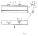
- Fig. 2
- das Positionierelement in Seiten-, Drauf- und Stirnansicht,
- Fig. 3
- den Schraubkanal des Pfostens,
- Fig. 4
- eine weitere Ausführungsform des Positionierelementes in Seiten-, Drauf- und Stirnansicht,
- Fig. 5
- eine Anwendung des Positionierelements nach Fig. 4.
- Fig. 1
- 2 shows a perspective illustration of a frame construction made of mullions and transoms according to the invention, only partially reproduced,
- Fig. 2
- the positioning element in side, top and front view,
- Fig. 3
- the screw channel of the post,
- Fig. 4
- another embodiment of the positioning element in side, top and end views,
- Fig. 5
- an application of the positioning element according to FIG. 4.
Die in der Zeichnung nur teilweise, nämlich im
Eckbereich dargestellte Rahmenkonstruktion ist aus
Pfosten 1 und Riegeln 2 in Form von Hohlprofilen
aufgebaut. Derartige Rahmenkonstruktionen finden
insbesondere bei Fassaden oder dergleichen Anwendung.
Im Kreuzungsbereich dieser Rahmenkonstruktionen
überlappen sich die Pfosten 1 und Riegel 2
gegenseitig, wozu der Riegel 2, wie dies in Fig. 1 zu
sehen ist, an seiner Unterseite in der Regel
ausgeklinkt ist.Only partially in the drawing, namely in
The corner structure shown is made of
Die gegenseitige Verschraubung erfolgt im
Überlappungsbereich, wozu am Riegel 2 in der Regel
zwei Ausnehmungen 3 in Form von Bohrungen vorgesehen
sind, durch die hindurch Schrauben in einen am
Pfosten 1 angeordneten Schraubkanal 4 eingedreht
werden. Die Schrauben sind dabei an die Breite des
Schraubkanals 4 bzw. dem Abstand der Nutwandungen so
angepaßt, daß das Gewinde in die Nutwand einfurcht.
Die Nut bzw. der Schraubkanal 4 selbst verläuft, wie
dies in Fig. 1 zu sehen ist, in Längsrichtung des
Pfostens 1.The mutual screwing takes place in the
Overlap area, which is usually the case on
In den Schraubkanal 4 ist zur Erleichterung der
Montage des Riegels 2 ein Positionierelement 5
eingesetzt, das in der Ausführungsform nach den Fig. 4
und 5 eine, in der Ausführungsform nach den Fig. 1 bis
3 dagegen zwei über den äußeren Rand des
Schraubkanals 4 nach außen vorstehende Noppen 6
aufweist. Diese Noppen 6 dienen als Zentrierung für
die im Riegel 2 vorgesehenen Ausnehmungen 3. Weiter
trägt das Positionierelement 5 zwei seitlich
vorstehende Distanzstege 7, die der an den Rand des
Schraubkanals 4 anschließenden Stirnfläche 8
aufliegen. Diese Distanzstege 7 sorgen dafür, daß der
Riegel 2 nicht unmittelbar auf den Pfosten 1, also
Metall auf Metall, zu liegen kommt.In the
Die Noppen 6 weisen eine an die Form der Bohrung im
Riegel 2 angepaßte zylindrische Mantelfläche auf.The
Wie insbesondere den Fig. 1 und 2 zu entnehmen ist,
ist der eine Distanzsteg 7 des Positionierelementes 5
mit einer Positioniermarkierung 9 in Form einer
Einkerbung versehen, die bei der Montage auf eine in
der Fig. 1 strichpunktierte Linie 10 ausgerichtet
wird. Hierdurch wird eine erhebliche Vereinfachung bei
der Montage erreicht, da zunächst das selbsttätig in
dem Schraubkanal 4 gehaltene Positionierelement 5 ohne
weiteres ausgerichtet werden kann, so daß im Anschluß
daran lediglich noch der Riegel 2 auf die vorstehenden
Noppen 6 des Positionierelementes 5 mit seinen
Bohrungen aufgesetzt werden muß. Die Ausrichtung wird
dadurch wesentlich erleichtert, da der Riegel 2
nämlich nach dem Aufsetzen auf den Pfosten 1 in der
Regel die an dem Pfosten 1 angebrachten
Markierungshilfslinien 10 verdeckt. Die
Positioniermarkierungen 9 am Positionierelement 5 sind
im Ausführungsbeispiel mittig zwischen den beiden
Noppen 6 angeordnet, können sich jedoch auch an jeder
anderen beliebigen Stelle befinden.As can be seen in particular from FIGS. 1 and 2,
is the one spacer web 7 of the
Um den Halt des Positionierelementes 5 im
Schraubkanal 4 weiter zu verbessern, weist dieses zwei
zu den Distanzstegen 7 parallel verlaufende
Rastleisten 11 auf, die in Rastnuten 12 in der Wand
des Schraubkanals 4 greifen. Die Rastleisten 11 sind
in Fig. 2, die Rastnuten 12 dagegen insbesondere in
Fig. 3 gut zu erkennen. Weiter zeigen diese beiden
Figuren, daß das Positionierelement 5 in seiner
Formgestaltung dem Schraubkanal 4 angepaßt ist, so daß
es im eingebauten Zustand formschlüssig im
Schraubkanal 4 angeordnet ist.To hold the
Um das Eindrehen der Schraube nach Anbringung des
Riegels zu vereinfachen, weisen die Noppen 6 jeweils
ein zentrisch angeordnetes Sackloch 13 auf, das als
Zentrierungshilfe dient.To tighten the screw after attaching the
To simplify the bar, the
Wie schließlich aus der Fig. 1 sowie der Fig. 4 zu
erkennen ist, erstreckt sich das Positionierelement 5
etwa über die gesamte Breite des Riegels 2, so daß
eine vollständige Anlage des Riegels 2 über die
Distanzstege 7 am Pfosten 1 gewährleistet ist.As finally from FIG. 1 and FIG. 4 too
is recognizable, the
Claims (10)
Applications Claiming Priority (2)
| Application Number | Priority Date | Filing Date | Title |
|---|---|---|---|
| DE19647911 | 1996-11-20 | ||
| DE19647911A DE19647911C2 (en) | 1996-11-20 | 1996-11-20 | Frame construction consisting of mullions and transoms in the form of hollow profiles |
Publications (2)
| Publication Number | Publication Date |
|---|---|
| EP0844341A1 true EP0844341A1 (en) | 1998-05-27 |
| EP0844341B1 EP0844341B1 (en) | 2003-02-26 |
Family
ID=7812165
Family Applications (1)
| Application Number | Title | Priority Date | Filing Date |
|---|---|---|---|
| EP97117357A Expired - Lifetime EP0844341B1 (en) | 1996-11-20 | 1997-10-08 | Framestructure in mullion-transom hollow profile form |
Country Status (6)
| Country | Link |
|---|---|
| EP (1) | EP0844341B1 (en) |
| AT (1) | ATE233352T1 (en) |
| CZ (1) | CZ293019B6 (en) |
| DE (2) | DE19647911C2 (en) |
| PL (1) | PL189809B1 (en) |
| PT (1) | PT844341E (en) |
Cited By (2)
| Publication number | Priority date | Publication date | Assignee | Title |
|---|---|---|---|---|
| WO2001027399A3 (en) * | 1999-10-08 | 2001-10-04 | Diversified Panel Systems Inc | Curtain wall support method and apparatus |
| US6745527B1 (en) | 1999-10-08 | 2004-06-08 | Diversified Panel Systems, Inc. | Curtain wall support method and apparatus |
Families Citing this family (1)
| Publication number | Priority date | Publication date | Assignee | Title |
|---|---|---|---|---|
| PL403743A1 (en) | 2013-05-02 | 2014-11-10 | Gil Jerzy Firma Produkcyjno-Handlowa Seppa Spółka Cywilna | Set of design elements for fastening facade panels |
Citations (5)
| Publication number | Priority date | Publication date | Assignee | Title |
|---|---|---|---|---|
| FR2439275A1 (en) * | 1978-10-16 | 1980-05-16 | Alusuisse | THERMALLY INSULATING FACADE EQUIPMENT |
| DE8617042U1 (en) * | 1986-06-26 | 1989-10-05 | Fa. Eduard Hueck, 5880 Luedenscheid, De | |
| US4899508A (en) * | 1988-04-28 | 1990-02-13 | Butler Manufacturing Company | Panel and glass curtain wall system |
| EP0436869A2 (en) * | 1990-01-12 | 1991-07-17 | Reynolds Aluminium Deutschland, Internationale Vertriebsgesellschaft Mbh | Butt joint junction between column and crossbar of a supporting structure of or for a façade wall |
| DE4040006A1 (en) * | 1990-12-14 | 1992-06-17 | Glasbau Seele Gmbh | Framework for glass panelling - uses low profile section held together by cross-bar holder with laterally extending arms |
Family Cites Families (4)
| Publication number | Priority date | Publication date | Assignee | Title |
|---|---|---|---|---|
| DE3843737A1 (en) * | 1988-12-22 | 1990-07-05 | Mannesmann Ag | LATCH HOLDER FOR A FACADE WALL CONSTRUCTION |
| DE3906035A1 (en) * | 1989-02-27 | 1990-08-30 | Herbert Lacker | FRAME DESIGN |
| DE3938775A1 (en) * | 1989-11-23 | 1991-05-29 | Schueco Int Gmbh & Co | T-CONNECTION BETWEEN TWO PROFILES, PREFERABLY A RUNG AND A POST PROFILE OF A FACADE |
| DE9305394U1 (en) * | 1993-04-08 | 1994-08-11 | Kawneer Aluminium Gmbh | Frame construction, especially for facade cladding |
-
1996
- 1996-11-20 DE DE19647911A patent/DE19647911C2/en not_active Expired - Fee Related
-
1997
- 1997-10-08 EP EP97117357A patent/EP0844341B1/en not_active Expired - Lifetime
- 1997-10-08 AT AT97117357T patent/ATE233352T1/en active
- 1997-10-08 DE DE59709384T patent/DE59709384D1/en not_active Expired - Lifetime
- 1997-10-08 PT PT97117357T patent/PT844341E/en unknown
- 1997-11-18 PL PL97323210A patent/PL189809B1/en not_active IP Right Cessation
- 1997-11-20 CZ CZ19973686A patent/CZ293019B6/en not_active IP Right Cessation
Patent Citations (5)
| Publication number | Priority date | Publication date | Assignee | Title |
|---|---|---|---|---|
| FR2439275A1 (en) * | 1978-10-16 | 1980-05-16 | Alusuisse | THERMALLY INSULATING FACADE EQUIPMENT |
| DE8617042U1 (en) * | 1986-06-26 | 1989-10-05 | Fa. Eduard Hueck, 5880 Luedenscheid, De | |
| US4899508A (en) * | 1988-04-28 | 1990-02-13 | Butler Manufacturing Company | Panel and glass curtain wall system |
| EP0436869A2 (en) * | 1990-01-12 | 1991-07-17 | Reynolds Aluminium Deutschland, Internationale Vertriebsgesellschaft Mbh | Butt joint junction between column and crossbar of a supporting structure of or for a façade wall |
| DE4040006A1 (en) * | 1990-12-14 | 1992-06-17 | Glasbau Seele Gmbh | Framework for glass panelling - uses low profile section held together by cross-bar holder with laterally extending arms |
Cited By (3)
| Publication number | Priority date | Publication date | Assignee | Title |
|---|---|---|---|---|
| WO2001027399A3 (en) * | 1999-10-08 | 2001-10-04 | Diversified Panel Systems Inc | Curtain wall support method and apparatus |
| US6745527B1 (en) | 1999-10-08 | 2004-06-08 | Diversified Panel Systems, Inc. | Curtain wall support method and apparatus |
| US6748709B1 (en) | 1999-10-08 | 2004-06-15 | Diversified Panel Systems, Inc. | Curtain wall support method and apparatus |
Also Published As
| Publication number | Publication date |
|---|---|
| CZ368697A3 (en) | 1998-07-15 |
| ATE233352T1 (en) | 2003-03-15 |
| DE59709384D1 (en) | 2003-04-03 |
| CZ293019B6 (en) | 2004-01-14 |
| PL189809B1 (en) | 2005-09-30 |
| PT844341E (en) | 2003-06-30 |
| PL323210A1 (en) | 1998-05-25 |
| DE19647911A1 (en) | 1998-06-10 |
| DE19647911C2 (en) | 1998-10-15 |
| EP0844341B1 (en) | 2003-02-26 |
Similar Documents
| Publication | Publication Date | Title |
|---|---|---|
| DE102009012438B4 (en) | pinheader | |
| EP0436869A2 (en) | Butt joint junction between column and crossbar of a supporting structure of or for a façade wall | |
| DE19641500C2 (en) | Device for releasably connecting profile bars | |
| DE1683548C3 (en) | Adjusting device for components such as frames, plates or the like. preferably of prefabricated structures | |
| EP0369326A2 (en) | Insulating connection device for building panels | |
| EP0844341B1 (en) | Framestructure in mullion-transom hollow profile form | |
| DE3539002C2 (en) | ||
| DE3422222A1 (en) | Stand comprising a profiled bar and a panel or similar stand part attached thereto by means of a connector | |
| DE3743041C1 (en) | Method for producing a frame element consisting of interconnected hollow-profile beams and punching device for carrying out the method | |
| DE2751520C3 (en) | Sound-insulating wall made of self-supporting, prefabricated panels | |
| EP1342861B1 (en) | Connection device | |
| EP0149587B1 (en) | support piece for transoms of a curtain wall structure composed of hollow profile members | |
| EP1826331A2 (en) | Mounting aid and post-crossbar construction | |
| DE3225513A1 (en) | Panel-shaped building member having connection profile bars attached to the edges | |
| DE3540848A1 (en) | Mortise lock with a variable spindle dimension | |
| DE2720381A1 (en) | U=Shaped lintel for wing hung either way - has hole sloping between cover bar blind holes engaged by bolt sockets | |
| EP0816623B1 (en) | Profile element for constructing door or window frames and façade constructions | |
| CH670863A5 (en) | ||
| DE3535080C1 (en) | Light-admitting plastic-sheeting element | |
| DE19734876A1 (en) | Connecting element for joining hollow part and abutting profiled part | |
| DE202004009649U1 (en) | Connecting system for profiled frame elements for garden fencing etc has first and second connecting elements with interengaging catches and locking members held in keyed engagement for double boundary force lock | |
| DE3134162A1 (en) | Clamping device for the fastening of fitting parts | |
| DE2604814A1 (en) | Insulating window or door bar piece connector - comprising two bolt linked parts with hooks engaging interfacing ribs | |
| CH510811A (en) | Frame for holding glass panels in buildings | |
| DE7121021U (en) | Espagnolette |
Legal Events
| Date | Code | Title | Description |
|---|---|---|---|
| PUAI | Public reference made under article 153(3) epc to a published international application that has entered the european phase |
Free format text: ORIGINAL CODE: 0009012 |
|
| AK | Designated contracting states |
Kind code of ref document: A1 Designated state(s): AT BE CH DE DK FR GB IE IT LI LU NL PT SE |
|
| AX | Request for extension of the european patent |
Free format text: AL;LT;LV;RO;SI |
|
| 17P | Request for examination filed |
Effective date: 19980408 |
|
| AKX | Designation fees paid |
Free format text: AT BE CH DE DK FR GB IE IT LI LU NL PT SE |
|
| RBV | Designated contracting states (corrected) |
Designated state(s): AT BE CH DE DK FR GB IE IT LI LU NL PT SE |
|
| GRAG | Despatch of communication of intention to grant |
Free format text: ORIGINAL CODE: EPIDOS AGRA |
|
| 17Q | First examination report despatched |
Effective date: 20020403 |
|
| GRAG | Despatch of communication of intention to grant |
Free format text: ORIGINAL CODE: EPIDOS AGRA |
|
| GRAH | Despatch of communication of intention to grant a patent |
Free format text: ORIGINAL CODE: EPIDOS IGRA |
|
| GRAH | Despatch of communication of intention to grant a patent |
Free format text: ORIGINAL CODE: EPIDOS IGRA |
|
| GRAA | (expected) grant |
Free format text: ORIGINAL CODE: 0009210 |
|
| AK | Designated contracting states |
Designated state(s): AT BE CH DE DK FR GB IE IT LI LU NL PT SE |
|
| REG | Reference to a national code |
Ref country code: GB Ref legal event code: FG4D Free format text: NOT ENGLISH |
|
| REG | Reference to a national code |
Ref country code: CH Ref legal event code: NV Representative=s name: ISLER & PEDRAZZINI AG Ref country code: CH Ref legal event code: EP |
|
| GBT | Gb: translation of ep patent filed (gb section 77(6)(a)/1977) |
Effective date: 20030226 |
|
| REG | Reference to a national code |
Ref country code: IE Ref legal event code: FG4D Free format text: GERMAN |
|
| REF | Corresponds to: |
Ref document number: 59709384 Country of ref document: DE Date of ref document: 20030403 Kind code of ref document: P |
|
| PG25 | Lapsed in a contracting state [announced via postgrant information from national office to epo] |
Ref country code: DK Free format text: LAPSE BECAUSE OF FAILURE TO SUBMIT A TRANSLATION OF THE DESCRIPTION OR TO PAY THE FEE WITHIN THE PRESCRIBED TIME-LIMIT Effective date: 20030526 |
|
| REG | Reference to a national code |
Ref country code: SE Ref legal event code: TRGR |
|
| REG | Reference to a national code |
Ref country code: PT Ref legal event code: SC4A Free format text: AVAILABILITY OF NATIONAL TRANSLATION Effective date: 20030509 |
|
| PG25 | Lapsed in a contracting state [announced via postgrant information from national office to epo] |
Ref country code: LU Free format text: LAPSE BECAUSE OF NON-PAYMENT OF DUE FEES Effective date: 20031008 |
|
| ET | Fr: translation filed | ||
| PLBE | No opposition filed within time limit |
Free format text: ORIGINAL CODE: 0009261 |
|
| STAA | Information on the status of an ep patent application or granted ep patent |
Free format text: STATUS: NO OPPOSITION FILED WITHIN TIME LIMIT |
|
| 26N | No opposition filed |
Effective date: 20031127 |
|
| PGFP | Annual fee paid to national office [announced via postgrant information from national office to epo] |
Ref country code: PT Payment date: 20050927 Year of fee payment: 9 |
|
| PG25 | Lapsed in a contracting state [announced via postgrant information from national office to epo] |
Ref country code: PT Free format text: LAPSE BECAUSE OF NON-PAYMENT OF DUE FEES Effective date: 20070409 |
|
| REG | Reference to a national code |
Ref country code: PT Ref legal event code: MM4A Free format text: LAPSE DUE TO NON-PAYMENT OF FEES Effective date: 20070409 |
|
| REG | Reference to a national code |
Ref country code: CH Ref legal event code: PCAR Free format text: ISLER & PEDRAZZINI AG;POSTFACH 1772;8027 ZUERICH (CH) |
|
| PGFP | Annual fee paid to national office [announced via postgrant information from national office to epo] |
Ref country code: NL Payment date: 20101013 Year of fee payment: 14 Ref country code: IE Payment date: 20101021 Year of fee payment: 14 Ref country code: AT Payment date: 20101014 Year of fee payment: 14 |
|
| PGFP | Annual fee paid to national office [announced via postgrant information from national office to epo] |
Ref country code: IT Payment date: 20101026 Year of fee payment: 14 Ref country code: GB Payment date: 20101021 Year of fee payment: 14 |
|
| PGFP | Annual fee paid to national office [announced via postgrant information from national office to epo] |
Ref country code: CH Payment date: 20111024 Year of fee payment: 15 Ref country code: SE Payment date: 20111021 Year of fee payment: 15 |
|
| REG | Reference to a national code |
Ref country code: NL Ref legal event code: V1 Effective date: 20120501 |
|
| GBPC | Gb: european patent ceased through non-payment of renewal fee |
Effective date: 20111008 |
|
| PG25 | Lapsed in a contracting state [announced via postgrant information from national office to epo] |
Ref country code: NL Free format text: LAPSE BECAUSE OF NON-PAYMENT OF DUE FEES Effective date: 20120501 |
|
| REG | Reference to a national code |
Ref country code: IE Ref legal event code: MM4A |
|
| PG25 | Lapsed in a contracting state [announced via postgrant information from national office to epo] |
Ref country code: GB Free format text: LAPSE BECAUSE OF NON-PAYMENT OF DUE FEES Effective date: 20111008 Ref country code: IT Free format text: LAPSE BECAUSE OF NON-PAYMENT OF DUE FEES Effective date: 20111008 |
|
| PG25 | Lapsed in a contracting state [announced via postgrant information from national office to epo] |
Ref country code: IE Free format text: LAPSE BECAUSE OF NON-PAYMENT OF DUE FEES Effective date: 20111008 |
|
| REG | Reference to a national code |
Ref country code: AT Ref legal event code: MM01 Ref document number: 233352 Country of ref document: AT Kind code of ref document: T Effective date: 20111008 |
|
| PG25 | Lapsed in a contracting state [announced via postgrant information from national office to epo] |
Ref country code: AT Free format text: LAPSE BECAUSE OF NON-PAYMENT OF DUE FEES Effective date: 20111008 |
|
| PGFP | Annual fee paid to national office [announced via postgrant information from national office to epo] |
Ref country code: FR Payment date: 20121031 Year of fee payment: 16 Ref country code: BE Payment date: 20121022 Year of fee payment: 16 |
|
| REG | Reference to a national code |
Ref country code: CH Ref legal event code: PL |
|
| PG25 | Lapsed in a contracting state [announced via postgrant information from national office to epo] |
Ref country code: CH Free format text: LAPSE BECAUSE OF NON-PAYMENT OF DUE FEES Effective date: 20121031 Ref country code: LI Free format text: LAPSE BECAUSE OF NON-PAYMENT OF DUE FEES Effective date: 20121031 Ref country code: SE Free format text: LAPSE BECAUSE OF NON-PAYMENT OF DUE FEES Effective date: 20121009 |
|
| BERE | Be: lapsed |
Owner name: *NORSK HYDRO ASA Effective date: 20131031 |
|
| REG | Reference to a national code |
Ref country code: FR Ref legal event code: ST Effective date: 20140630 |
|
| PG25 | Lapsed in a contracting state [announced via postgrant information from national office to epo] |
Ref country code: FR Free format text: LAPSE BECAUSE OF NON-PAYMENT OF DUE FEES Effective date: 20131031 |
|
| PG25 | Lapsed in a contracting state [announced via postgrant information from national office to epo] |
Ref country code: BE Free format text: LAPSE BECAUSE OF NON-PAYMENT OF DUE FEES Effective date: 20131031 |
|
| REG | Reference to a national code |
Ref country code: DE Ref legal event code: R082 Ref document number: 59709384 Country of ref document: DE Representative=s name: FAY UND KOLLEGEN, DE |
|
| REG | Reference to a national code |
Ref country code: DE Ref legal event code: R082 Ref document number: 59709384 Country of ref document: DE Representative=s name: FAY UND KOLLEGEN, DE Effective date: 20141017 Ref country code: DE Ref legal event code: R081 Ref document number: 59709384 Country of ref document: DE Owner name: SAPA AS, NO Free format text: FORMER OWNER: NORSK HYDRO ASA, OSLO, NO Effective date: 20141017 |
|
| PGFP | Annual fee paid to national office [announced via postgrant information from national office to epo] |
Ref country code: DE Payment date: 20151022 Year of fee payment: 19 |
|
| REG | Reference to a national code |
Ref country code: DE Ref legal event code: R119 Ref document number: 59709384 Country of ref document: DE |
|
| PG25 | Lapsed in a contracting state [announced via postgrant information from national office to epo] |
Ref country code: DE Free format text: LAPSE BECAUSE OF NON-PAYMENT OF DUE FEES Effective date: 20170503 |