EP0844144A1 - Gassack-Modul - Google Patents
Gassack-Modul Download PDFInfo
- Publication number
- EP0844144A1 EP0844144A1 EP97120118A EP97120118A EP0844144A1 EP 0844144 A1 EP0844144 A1 EP 0844144A1 EP 97120118 A EP97120118 A EP 97120118A EP 97120118 A EP97120118 A EP 97120118A EP 0844144 A1 EP0844144 A1 EP 0844144A1
- Authority
- EP
- European Patent Office
- Prior art keywords
- airbag module
- module according
- fastening device
- gas source
- compressed gas
- Prior art date
- Legal status (The legal status is an assumption and is not a legal conclusion. Google has not performed a legal analysis and makes no representation as to the accuracy of the status listed.)
- Withdrawn
Links
Images


Classifications
-
- B—PERFORMING OPERATIONS; TRANSPORTING
- B60—VEHICLES IN GENERAL
- B60R—VEHICLES, VEHICLE FITTINGS, OR VEHICLE PARTS, NOT OTHERWISE PROVIDED FOR
- B60R21/00—Arrangements or fittings on vehicles for protecting or preventing injuries to occupants or pedestrians in case of accidents or other traffic risks
- B60R21/02—Occupant safety arrangements or fittings, e.g. crash pads
- B60R21/16—Inflatable occupant restraints or confinements designed to inflate upon impact or impending impact, e.g. air bags
- B60R21/20—Arrangements for storing inflatable members in their non-use or deflated condition; Arrangement or mounting of air bag modules or components
- B60R21/217—Inflation fluid source retainers, e.g. reaction canisters; Connection of bags, covers, diffusers or inflation fluid sources therewith or together
Definitions
- the invention relates to an airbag module with a folded airbag, which has an injection mouth, a frame part for fastening of the gas bag, which is arranged inside the gas bag and the Blow-in surrounds a tubular compressed gas source that has an outflow end has, and a fastening device through which the Position of the gas bag is determined relative to the compressed gas source.
- Such airbag modules of this type are known to the person skilled in the art Known in the field of vehicle occupant safety technology. Usually a so-called gas generator with a pyrotechnic Charge used after activation in a very short time releases a predetermined volume of gas. Beyond that, however also so-called HGI gas generators (heated gas inflator) in gas bag modules been built in, which is characterized by good environmental compatibility award. To attach all parts of the module So far, numerous individual parts have been required. The compressed gas source itself has so far usually been in a pressure gas source enclosing Housed and clamped in sheet metal housing. The frame part will also locked to the sheet metal housing by means of bolts.
- the tin case is not only used for fastening all parts and for fastening of the module on the vehicle, but it also serves to guide the gas.
- the outflow end of the compressed gas source which is in its longitudinal direction parallel to the inflow cross-sectional area defined by the blowing mouth extends of the gas bag, ends near a side wall of the Sheet metal housing. When the gas flows out, it is distributed in the Sheet metal casing evenly and flows through several openings in the Gas bag.
- the sheet metal housing is affected by the thrust caused by the Leakage of gas is caused and via the pressurized gas source in it is initiated, subject to high loads.
- the invention creates an airbag module that is simpler Manufacturing and assembly as well as a reduced weight distinguished.
- the total volume occupied by the module less than in previously known.
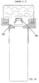
- an airbag module 10 is shown, which is in the dashboard of a vehicle can be installed.
- the gas bag module 10 has a folded gas bag 12 shown in more detail in FIG an injection mouth 14.
- a frame part 16 inside the gas bag 12 surrounds the blow-in mouth 14, which has an inflow opening 18 with an inflow cross-sectional area F defined.
- From inside the gas bag 12 protrude several threaded bolts 20 attached to the frame part 16 through the Frame part 16 and through openings, not shown, in the gas bag 12 Outside.
- a film 22 surrounds the folded gas bag 12, whereby a pre-assembled unit is created.
- a subsequent fastening device 24 is used to attach the unit to a tubular To attach compressed gas source 25 and, in addition, the gas bag module 10 to lock on the vehicle.
- the location of the built-in gas bag module 10 for the vehicle is shown in FIG. 1 based on the stylized Vehicle recognizable.
- the fastening device 24 consists of an upper clamping part 26 and a lower clamping part 28, each one half of a plate-like end flange 30 with an airbag 12 have facing flat front 32.
- the back is on everyone Half formed a half-shell 34, which after screwing together the clamping parts 26, 28 form a pipe section 44 (see FIG. 2) in the interior of which forms an opening 36 for receiving the compressed gas source 25 is.
- the opening 36 also extends through the flange 30 through it.
- the half-shells 34 have the shape of a clamp half laterally radially projecting ends 38.
- the compressed gas source 25 is through a tubular, circular cylindrical Labeled housing that extends to an outflow end 46 a neck portion 48 tapers.
- An ignition device 50 extends face from the outflow end 46 into the interior of the compressed gas source 25.
- An ignition cable 52 does not connect the igniter 50 to one shown trigger device, which in the case of retention a corresponding Outputs signal to the igniter 50.
- the turnstile 60 is integrally formed on the sealing collar 56 and projects axially therefrom. How As can be seen in FIG. 2, the compressed gas source 25 projects into the interior of the gas bag 12. After the compressed gas source 25 to the lower clamping part 28 is aligned, the upper clamping part 26 is placed and with the lower one fixed with the screws 40. The compressed gas source 25 on the one hand on the neck section 48 and on the other hand one Jacket section 62 radially clamped near the outlet opening 36. Subsequently the pre-assembled unit consists of gas bag 12 and frame part 16 attached to the flange 30 by nuts 64 on the by appropriate Openings in the flange 30 extend threaded bolts 20 screwed will. As a result, the gas bag 12 is in the region of the gas bag mouth 14 clamped between the frame part 16 and the flange 30.
- a hood-like cover 166 is integrally formed, the course of which is shown in Figures 7 to 10.
- the cover 166 is said electrical connecting parts, so the ignition cable 52 and the plug with which is connected to the igniter 50, before direct flow through Protect hot compressed gas.
- the cover 166 is designed that there are still numerous channels 168 through which the compressed gas can flow into the gas bag.
Abstract
Description
- Figur 1 eine perspektivische Explosionsdarstellung des erfindungsgemäßen Gassack-Moduls;
- Figur 2 eine Längsschnittansicht durch das erfindungsgemäße Gassack-Modul in zusammengebautem Zustand;
- Figur 3 einen Schnitt durch den zusammengefalteten Gassack;
- Figur 4 eine Rückansicht der bei dem erfindungsgemäßen Gassack-Modul verwendeten Befestigungseinrichtung,
- Figur 5 eine perspektivische Explosionsdarstellung einer weiteren Ausführungsform des erfindungsgemäßen Gassack-Moduls von schräg vorn,
- Figur 6 eine Explosionsansicht der weiteren Ausführungsform des Gassack-Moduls von schräg hinten,
- Figur 7 eine Vorderansicht der in den Figuren 5 und 6 ebenfalls gezeigten Befestigungseinrichtung mit montierter Druckgasquelle,
- Figur 8 eine Längsschnittansicht des Gassack-Moduls nach der Linie A-A in Figur 7,
- Figur 9 eine Längsschnittansicht durch das erfindungsgemäße Gassack-Modul nach der Linie B-B in Figur 7, und
- Figur 10 eine Längsschnittansicht durch das erfindungsgemäße Gassack-Modul nach der Linie C-C in Figur 7.
Claims (17)
- Gassack-Modul miteinem gefalteten Gassack (12), der einen Einblasmund (14) aufweist,einem Rahmenteil (16) zum Befestigen des Gassacks (12), der im Inneren des Gassacks (12) angeordnet ist und den Einblasmund (14) umgibt,einer rohrförmigen Druckgasquelle (25), die ein Ausströmende (46) aufweist, undeiner Befestigungseinrichtung (24), durch die die Lage des Gassacks (12) relativ zur Druckgasquelle (25) festgelegt wird,
dadurch gekennzeichnet, daß sich die Druckgasquelle (25) in Längsrichtung im wesentlichen rechtwinkelig zu der durch den Einblasmund (14) definierten Einströmquerschnittsfläche (F) des Gassacks (12) erstreckt. - Gassack-Modul nach Anspruch 1, dadurch gekennzeichnet, daß die Befestigungseinrichtung (24) aus mehreren, aneinander arretierbaren Klemmteilen (26, 28) zusammengesetzt ist, zwischen denen die Druckgasquelle (25) geklemmt ist.
- Gassack-Modul nach Anspruch 2, dadurch gekennzeichnet, daß die Befestigungseinrichtung (24) eine Öffnung (36) zur Aufnahme und zum radialen Klemmen der Druckgasquelle (25) im Bereich des Ausströmendes (46) aufweist und daß jedes Klemmteil (26, 28) eine Teilöffnung umfaßt und sich die Teilöffnungen zu der der Aufnahme der Druckgasquelle (25) dienenden Öffnung (36) ergänzen.
- Gassack-Modul nach Anspruch 1, dadurch gekennzeichnet, daß die Befestigungseinrichtung (24) einteilig ausgeführt ist und der Gasgenerator stirnseitig an dem Ausströmende (46) an der Befestigungseinrichtung (24) angebracht ist.
- Gassack-Modul nach einem der vorstehenden Ansprüche, dadurch gekennzeichnet, daß die Druckgasquelle (25) einen kreiszylindrischen Mantelabschnitt von im wesentlichen gleichbleibendem Querschnitt aufweist und die Befestigungseinrichtung (24) den Mantelabschnitt nahe des Ausströmendes (46) erfaßt.
- Gassack-Modul nach einem der vorstehenden Ansprüche, dadurch gekennzeichnet, daß der Gasgenerator stirnseitig am Ausströmende (46) mit der Befestigungseinrichtung (24) verschraubt ist.
- Gassack-Modul nach einem der vorstehenden Ansprüche, dadurch gekennzeichnet, daß sich die Druckgasquelle (25) in Richtung Ausströmende (46) hin verjüngt und einen Halsabschnitt (48) aufweist und daß die Befestigungseinrichtung (24) die Druckgasquelle (25) im Bereich des Halbabschnitts (48) klemmt.
- Gassack-Modul nach einem der vorstehenden Ansprüche, dadurch gekennzeichnet, daß die Befestigungseinrichtung (24) einen stirnseitigen Flansch (30) aufweist, an dem das Rahmenteil (16) arretiert werden kann, und daß der Gassack (12) zwischen dem Rahmenteil (16) und dem Flansch (30) im Bereich seines Einblasmundes (14) geklemmt ist.
- Gassack-Modul nach Anspruch 8, dadurch gekennzeichnet, daß an den stirnseitigen Flansch (30) ein Rohrabschnitt (44) angeformt ist, dessen Inneres die Öffnung (36) zur Aufnahme der Druckgasquelle (25) bildet.
- Gassack-Modul nach einem der vorstehenden Ansprüche, dadurch gekennzeichnet, daß die Befestigungseinrichtung (24) Befestigungsmittel (70) aufweist, mittels denen das Gassack-Modul (10) am Fahrzeug arretiert werden kann.
- Gassack-Modul nach einem der vorstehenden Ansprüche, dadurch gekennzeichnet, daß die Druckgasquelle (25) eine mantelseitige Abflachung (58) oder Vorsprung (158) und die Befestigungseinrichtung (24) eine entsprechende, daran angreifende Drehsperre (60) aufweist.
- Gassack-Modul nach einem der vorstehenden Ansprüche, dadurch gekennzeichnet, daß das Ausströmende (46) der Druckgasquelle (25) teilweise in das Innere des Gassacks (12) ragt.
- Gassack-Modul nach einem der vorstehenden Ansprüche, dadurch gekennzeichnet, daß in der Befestigungseinrichtung (24) wenigstens ein Kabelführungskanal (54) zur lagesicheren Arretierung eines Zündkabels (52) vorgesehen ist.
- Gassack-Modul nach einem der vorstehenden Ansprüche, dadurch gekennzeichnet, daß die Befestigungseinrichtung (24) aus mehreren Kunststoffspritzgußteilen besteht.
- Gassack-Modul nach einem der Ansprüche 1 bis 13, dadurch gekennzeichnet, daß die Befestigungseinrichtung (25) aus mehreren Leichtmetalldruckgußteilen besteht.
- Gassack-Modul nach einem der vorstehenden Ansprüche, dadurch gekennzeichnet, daß die Aufnahmeöffnung (36) zum Gassack (12) hin durch einen ringförmigen, an der Befestigungseinrichtung (24) angeformten Dichtbund (56) abgeschlossen ist, der gasdicht an der Druckgasquelle (25) anliegt.
- Gassack-Modul nach einem der vorstehenden Ansprüche, dadurch gekennzeichnet, daß eine haubenartige Abdeckung (166) im Gassack-Modul vorgesehen ist, die das Ausströmende (46) teilweise umgibt und wobei elektrische Anschlußteile zum Aktivieren der Druckgasquelle vorgesehen sind, die vor direktem Anströmen durch heißes Gas durch die Abdeckung (166) geschützt sind.
Applications Claiming Priority (2)
| Application Number | Priority Date | Filing Date | Title |
|---|---|---|---|
| DE29620298U | 1996-11-21 | ||
| DE29620298U DE29620298U1 (de) | 1996-11-21 | 1996-11-21 | Gassack-Modul |
Publications (1)
| Publication Number | Publication Date |
|---|---|
| EP0844144A1 true EP0844144A1 (de) | 1998-05-27 |
Family
ID=8032294
Family Applications (1)
| Application Number | Title | Priority Date | Filing Date |
|---|---|---|---|
| EP97120118A Withdrawn EP0844144A1 (de) | 1996-11-21 | 1997-11-17 | Gassack-Modul |
Country Status (5)
| Country | Link |
|---|---|
| EP (1) | EP0844144A1 (de) |
| JP (1) | JPH10157545A (de) |
| KR (1) | KR19980042610A (de) |
| DE (1) | DE29620298U1 (de) |
| ES (1) | ES2118693T1 (de) |
Cited By (2)
| Publication number | Priority date | Publication date | Assignee | Title |
|---|---|---|---|---|
| WO2006066557A1 (de) * | 2004-12-22 | 2006-06-29 | Takata-Petri Ag | Airbagmodul, insbesondere für den beifahrer- und kniebereich |
| US7614645B2 (en) | 2005-02-09 | 2009-11-10 | Takata-Petri Ag | Airbag module |
Families Citing this family (2)
| Publication number | Priority date | Publication date | Assignee | Title |
|---|---|---|---|---|
| DE19860932A1 (de) | 1998-12-30 | 2000-07-13 | Petri Ag | Airbagmodul |
| DE19905025C2 (de) | 1999-01-28 | 2003-11-13 | Takata Petri Ag | Airbagmodul |
Citations (4)
| Publication number | Priority date | Publication date | Assignee | Title |
|---|---|---|---|---|
| US4915410A (en) * | 1988-11-28 | 1990-04-10 | Trw Vehicle Safety Systems Inc. | Vehicle air bag module and method of assembly |
| US5423568A (en) * | 1992-10-30 | 1995-06-13 | Takata Corporation | Air bag device with an inflator mounting structure |
| US5511818A (en) * | 1995-08-16 | 1996-04-30 | Morton International, Inc. | Passenger side airbag module |
| US5553888A (en) * | 1995-06-26 | 1996-09-10 | Alliedsignal Inc. | Snap-on, removable steering wheel with integral airbag housing |
-
1996
- 1996-11-21 DE DE29620298U patent/DE29620298U1/de not_active Expired - Lifetime
-
1997
- 1997-11-17 EP EP97120118A patent/EP0844144A1/de not_active Withdrawn
- 1997-11-17 ES ES97120118T patent/ES2118693T1/es active Pending
- 1997-11-20 KR KR1019970061345A patent/KR19980042610A/ko not_active Application Discontinuation
- 1997-11-21 JP JP32158197A patent/JPH10157545A/ja active Pending
Patent Citations (4)
| Publication number | Priority date | Publication date | Assignee | Title |
|---|---|---|---|---|
| US4915410A (en) * | 1988-11-28 | 1990-04-10 | Trw Vehicle Safety Systems Inc. | Vehicle air bag module and method of assembly |
| US5423568A (en) * | 1992-10-30 | 1995-06-13 | Takata Corporation | Air bag device with an inflator mounting structure |
| US5553888A (en) * | 1995-06-26 | 1996-09-10 | Alliedsignal Inc. | Snap-on, removable steering wheel with integral airbag housing |
| US5511818A (en) * | 1995-08-16 | 1996-04-30 | Morton International, Inc. | Passenger side airbag module |
Non-Patent Citations (2)
| Title |
|---|
| "AIR BAG MODULE HAVING A VERTICALLY MOUNTED INFLATOR", RESEARCH DISCLOSURE, no. 391, November 1996 (1996-11-01), pages 711/712, XP000680918 * |
| "AIR BAG REACTION CANISTER", RESEARCH DISCLOSURE, no. 383, 1 March 1996 (1996-03-01), pages 222 - 224, XP000581363 * |
Cited By (2)
| Publication number | Priority date | Publication date | Assignee | Title |
|---|---|---|---|---|
| WO2006066557A1 (de) * | 2004-12-22 | 2006-06-29 | Takata-Petri Ag | Airbagmodul, insbesondere für den beifahrer- und kniebereich |
| US7614645B2 (en) | 2005-02-09 | 2009-11-10 | Takata-Petri Ag | Airbag module |
Also Published As
| Publication number | Publication date |
|---|---|
| DE29620298U1 (de) | 1997-03-20 |
| JPH10157545A (ja) | 1998-06-16 |
| KR19980042610A (ko) | 1998-08-17 |
| ES2118693T1 (es) | 1998-10-01 |
Similar Documents
| Publication | Publication Date | Title |
|---|---|---|
| DE3939311C2 (de) | Gassackeinheit und Verfahren zum Zusammenbauen einer solchen Gassackeinheit | |
| EP1851094B1 (de) | Airbagmodul für ein kraftfahrzeug | |
| EP0942852B1 (de) | Gassackmodul | |
| EP0704347B1 (de) | Gasgenerator | |
| EP0761506B1 (de) | Gassack-Rückhaltemodul | |
| DE4313616A1 (de) | Gassack-Rückhaltesystem für Fahrzeuge | |
| DE112014003348B4 (de) | Airbagmodul und Modulgehäuse | |
| DE4415374A1 (de) | Gassack-Modul | |
| DE4415373A1 (de) | Gasgenerator für ein Fahrzeug-Rückhaltesystem | |
| EP2134575B1 (de) | Gassackanordnungen für ein fahrzeuginsassen-rückhaltesystem | |
| DE4434739A1 (de) | Airbagaufblasvorrichtungsanordnung | |
| DE19717629A1 (de) | Lenkrad mit Airbagmodul | |
| EP1535810B1 (de) | Gasgenerator | |
| EP0820908B1 (de) | Gassack-Modul für ein Fahrzeuginsassen-Rückhaltesystem | |
| EP0844144A1 (de) | Gassack-Modul | |
| EP2958776B1 (de) | Airbagmodul für ein kraftfahrzeug | |
| EP2195204B1 (de) | Aufblaseinrichtung für ein airbagmodul | |
| EP1532024B1 (de) | Airbagmodul mit gasgenerator | |
| EP2176096B1 (de) | Airbagmodul für ein kraftfahrzeug | |
| EP1022196B1 (de) | Gassack-Rückhaltemodul | |
| DE19710063A1 (de) | Airbag mit Gaserzeuger | |
| EP2190699B1 (de) | Brennkammerbaueinheit für ein airbagmodul | |
| WO1997045300A1 (de) | Pyrotechnische antriebseinrichtung für einen gurtstraffer | |
| EP1533199A1 (de) | Gassackmodul | |
| DE19909426B4 (de) | Airbageinheit |
Legal Events
| Date | Code | Title | Description |
|---|---|---|---|
| PUAI | Public reference made under article 153(3) epc to a published international application that has entered the european phase |
Free format text: ORIGINAL CODE: 0009012 |
|
| AK | Designated contracting states |
Kind code of ref document: A1 Designated state(s): DE ES FR GB IT |
|
| AX | Request for extension of the european patent |
Free format text: AL;LT;LV;MK;RO;SI |
|
| RAP1 | Party data changed (applicant data changed or rights of an application transferred) |
Owner name: TRW OCCUPANT RESTRAINT SYSTEMS GMBH & CO. KG |
|
| GBC | Gb: translation of claims filed (gb section 78(7)/1977) | ||
| EL | Fr: translation of claims filed | ||
| REG | Reference to a national code |
Ref country code: ES Ref legal event code: BA2A Ref document number: 2118693 Country of ref document: ES Kind code of ref document: T1 |
|
| AKX | Designation fees paid |
Free format text: DE ES FR GB IT |
|
| RBV | Designated contracting states (corrected) |
Designated state(s): DE ES FR GB IT |
|
| STAA | Information on the status of an ep patent application or granted ep patent |
Free format text: STATUS: THE APPLICATION IS DEEMED TO BE WITHDRAWN |
|
| 18D | Application deemed to be withdrawn |
Effective date: 19981128 |