EP0843793B1 - Wegeventil - Google Patents
Wegeventil Download PDFInfo
- Publication number
- EP0843793B1 EP0843793B1 EP96919700A EP96919700A EP0843793B1 EP 0843793 B1 EP0843793 B1 EP 0843793B1 EP 96919700 A EP96919700 A EP 96919700A EP 96919700 A EP96919700 A EP 96919700A EP 0843793 B1 EP0843793 B1 EP 0843793B1
- Authority
- EP
- European Patent Office
- Prior art keywords
- slide
- snap
- locking
- control valve
- locking piston
- Prior art date
- Legal status (The legal status is an assumption and is not a legal conclusion. Google has not performed a legal analysis and makes no representation as to the accuracy of the status listed.)
- Expired - Lifetime
Links
- 238000006073 displacement reaction Methods 0.000 claims description 4
- 230000036316 preload Effects 0.000 description 7
- 230000008901 benefit Effects 0.000 description 6
- 230000008878 coupling Effects 0.000 description 6
- 238000010168 coupling process Methods 0.000 description 6
- 238000005859 coupling reaction Methods 0.000 description 6
- 238000004519 manufacturing process Methods 0.000 description 6
- 239000012530 fluid Substances 0.000 description 5
- 230000007935 neutral effect Effects 0.000 description 3
- 230000002093 peripheral effect Effects 0.000 description 3
- 230000009471 action Effects 0.000 description 2
- 230000004323 axial length Effects 0.000 description 2
- 238000010276 construction Methods 0.000 description 2
- 238000013461 design Methods 0.000 description 2
- 238000011161 development Methods 0.000 description 2
- 230000018109 developmental process Effects 0.000 description 2
- 238000010586 diagram Methods 0.000 description 2
- 230000000694 effects Effects 0.000 description 2
- 230000000284 resting effect Effects 0.000 description 2
- 230000006978 adaptation Effects 0.000 description 1
- 230000008859 change Effects 0.000 description 1
- 238000011982 device technology Methods 0.000 description 1
- 238000012423 maintenance Methods 0.000 description 1
- 230000004048 modification Effects 0.000 description 1
- 238000012986 modification Methods 0.000 description 1
- 238000012545 processing Methods 0.000 description 1
- 230000004043 responsiveness Effects 0.000 description 1
Images


Classifications
-
- F—MECHANICAL ENGINEERING; LIGHTING; HEATING; WEAPONS; BLASTING
- F16—ENGINEERING ELEMENTS AND UNITS; GENERAL MEASURES FOR PRODUCING AND MAINTAINING EFFECTIVE FUNCTIONING OF MACHINES OR INSTALLATIONS; THERMAL INSULATION IN GENERAL
- F16K—VALVES; TAPS; COCKS; ACTUATING-FLOATS; DEVICES FOR VENTING OR AERATING
- F16K11/00—Multiple-way valves, e.g. mixing valves; Pipe fittings incorporating such valves
- F16K11/02—Multiple-way valves, e.g. mixing valves; Pipe fittings incorporating such valves with all movable sealing faces moving as one unit
- F16K11/06—Multiple-way valves, e.g. mixing valves; Pipe fittings incorporating such valves with all movable sealing faces moving as one unit comprising only sliding valves, i.e. sliding closure elements
- F16K11/065—Multiple-way valves, e.g. mixing valves; Pipe fittings incorporating such valves with all movable sealing faces moving as one unit comprising only sliding valves, i.e. sliding closure elements with linearly sliding closure members
- F16K11/07—Multiple-way valves, e.g. mixing valves; Pipe fittings incorporating such valves with all movable sealing faces moving as one unit comprising only sliding valves, i.e. sliding closure elements with linearly sliding closure members with cylindrical slides
- F16K11/0704—Multiple-way valves, e.g. mixing valves; Pipe fittings incorporating such valves with all movable sealing faces moving as one unit comprising only sliding valves, i.e. sliding closure elements with linearly sliding closure members with cylindrical slides comprising locking elements
-
- F—MECHANICAL ENGINEERING; LIGHTING; HEATING; WEAPONS; BLASTING
- F15—FLUID-PRESSURE ACTUATORS; HYDRAULICS OR PNEUMATICS IN GENERAL
- F15B—SYSTEMS ACTING BY MEANS OF FLUIDS IN GENERAL; FLUID-PRESSURE ACTUATORS, e.g. SERVOMOTORS; DETAILS OF FLUID-PRESSURE SYSTEMS, NOT OTHERWISE PROVIDED FOR
- F15B13/00—Details of servomotor systems ; Valves for servomotor systems
- F15B13/02—Fluid distribution or supply devices characterised by their adaptation to the control of servomotors
- F15B13/04—Fluid distribution or supply devices characterised by their adaptation to the control of servomotors for use with a single servomotor
- F15B13/0401—Valve members; Fluid interconnections therefor
- F15B13/0402—Valve members; Fluid interconnections therefor for linearly sliding valves, e.g. spool valves
-
- F—MECHANICAL ENGINEERING; LIGHTING; HEATING; WEAPONS; BLASTING
- F15—FLUID-PRESSURE ACTUATORS; HYDRAULICS OR PNEUMATICS IN GENERAL
- F15B—SYSTEMS ACTING BY MEANS OF FLUIDS IN GENERAL; FLUID-PRESSURE ACTUATORS, e.g. SERVOMOTORS; DETAILS OF FLUID-PRESSURE SYSTEMS, NOT OTHERWISE PROVIDED FOR
- F15B2211/00—Circuits for servomotor systems
- F15B2211/30—Directional control
- F15B2211/32—Directional control characterised by the type of actuation
- F15B2211/321—Directional control characterised by the type of actuation mechanically
-
- Y—GENERAL TAGGING OF NEW TECHNOLOGICAL DEVELOPMENTS; GENERAL TAGGING OF CROSS-SECTIONAL TECHNOLOGIES SPANNING OVER SEVERAL SECTIONS OF THE IPC; TECHNICAL SUBJECTS COVERED BY FORMER USPC CROSS-REFERENCE ART COLLECTIONS [XRACs] AND DIGESTS
- Y10—TECHNICAL SUBJECTS COVERED BY FORMER USPC
- Y10T—TECHNICAL SUBJECTS COVERED BY FORMER US CLASSIFICATION
- Y10T137/00—Fluid handling
- Y10T137/8593—Systems
- Y10T137/86485—Line condition change responsive release of valve
Definitions
- the invention relates to a directional valve with a locking device to determine a directional spool in at least one switch position according to the preamble of Claim 1 and a locking device for such Directional control valve.
- valve devices are, for example for agricultural vehicles with hydraulic auxiliary devices used.
- the generic Valve arrangements fulfill a triple benefit, which is that the conventional valve arrangement Control of the lifting cylinder of an additional device, such as a front loader.
- Another benefit should be that about the Valve arrangement another additional device, such as a hydraulic motor can be controlled, in which the hydraulic fluid supply is controlled via the directional valve, depending on the direction of rotation of the hydraulic motor Lockable in two end positions using a locking device should be.
- the third benefit is in that the locking function in certain applications should be canceled, for example, when they are reached pushed out the end position of a hydraulic cylinder becomes. This "pushing out” is usually called Called "kickout".
- valve arrangement is intended for a permanent locking of a valve spool of the directional valve, a release of the locking when a predetermined load pressure is exceeded and an Mode in which the effect of the locking device is complete is canceled, made possible.
- a valve arrangement is included in EP 0 394 860 B1 a directional control valve and a locking device are disclosed, which enables the above-mentioned triple benefit becomes.
- There is an axial bore in the directional valve spool provided, in which a locking piston of a locking part is added is, through the engagement body through the peripheral wall of the directional valve spool into the corresponding one Grooves of the valve housing can be preloaded.
- the control of the locking piston takes place via a valve slide a kickout arrangement, via which a system pressure to Locking piston is feasible to produce the locking engagement.
- a connection to the slide of the kickout arrangement opened a tank, so that the resting on the locking piston The pressure is released and the locking engagement is released.
- the Triggering force of the kickout arrangement can be via a Adjust the actuating device by an operator.
- the means in the known valve arrangement can be a corresponding setting of the triggering force Lock, kick out when exceeded a predetermined control pressure and a cancellation of Locking by setting a minimum release force select.
- a valve arrangement is known from GB-A-1227539, where only an adjustment between one constant locking engagement of the locking device and one Position in which the locking engagement is released, possible is. This means that a kickout function is known for this Valve arrangement not provided.
- a valve arrangement is known from US-A-3132668, where a kickout function is provided, by the operator, however, no switching between a locking position and a position in which the locking engagement is canceled, can be made.
- the invention is based on the object a directional valve with a locking device for fixing of a directional valve spool and an arrangement to create a directional valve where minimal equipment requirements to meet all requirements the functions of a locking device is done enough.
- the arrangement of a switching device assign, via a slider of the kickout arrangement a system pressure can be fed in the same Direction as a kickout spring of the slider can the control pressure applied to the spool can be overridden. In this way the kickout function can be canceled, without the adjustment of the actuator - that is the spring preload of the kickout spring - is changed.
- the configuration of the valve arrangement according to the invention thus enables the kickout function to be switched off, without making a change to the actuating device becomes. After switching on the Kickout function, by pressing the Switching device, the kickout arrangement with your operated kickout spring preload.
- the measure according to the invention is thus the functional reliability and ease of use of the Valve arrangement considerably compared to conventional solutions been improved.
- Such a locking device can be used independently from a switching device at a directional valve and at use other applications.
- a compact unit is obtained when the components the valve assembly, that is, the locking part, the Kickout arrangement, the actuating device and the switching device coaxially one behind the other in a valve housing bore are included.
- This variant must only a comparatively simple valve housing bore be provided while the directional valve spool can be designed as a full piston.
- the spring rate of a kickout spring can be adjusted to Reduce the minimum by using the locking piston with a lower one Diameter when the slider is running, so that there is a piston unit in the form of a stepped piston results. This structure ensures that the Kickout spring only the result of the Compressive forces on the end face of the locking piston and Counteracts slider.
- a particularly simple, pre-assembled One receives unit when the locking piston and the slide are recorded in a common socket, which in turn is rotatably received in the valve housing and represents a rotary valve of the switching device.
- the pre-assembled unit can be pre-tested Assembly are trained so that the manufacture of Directional control valve according to the invention is further simplified.
- a such pre-testable assembly is also an object of the subordinate claim 13.
- the socket can only be used for recording be provided by slide and switching device, received in a valve housing bore during the locking piston which extends in extension of the socket.
- Locking pistons can prevent pressure fluctuations on the spool and slide connected to each other via a tie rod be that is anchored in the locking piston, and the only after a predetermined dead stroke of the slide in system reaches this, so that only after the dead stroke mechanical coupling of locking piston and slide takes place.
- control pressure and the system pressure are preferred tapped from a working connection of the directional valve.
- a particularly compact and easy to manufacture unit is obtained when the axis of the locking device is approximately is perpendicular to the directional valve spool axis, so that the valve bore for receiving the bush etc. as Radial bore for directional valve bore is executed.
- the biasing force of the detent spring can be set to one maintain predetermined, constant pressure by the locking piston in its resting position on a mechanical stop is present.
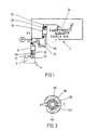
- the hydraulic circuit diagram is one Latching device 2 shown for a directional valve 4, from which only the directional valve slide 6 is indicated.
- the locking device 2 has a locking part 8, the Locking piston via a locking spring 10 onto an engagement part, for example, a detent ball 12 that engages can be brought with a locking groove 14 of the directional valve spool 6.
- the latching device 2 has a kickout arrangement 16, whose slider via a coupling device 18 mechanically connected to the locking piston of the locking part 8 is.
- the coupling device 18 has, for example a tie rod that hits a stop after a dead stroke 19 runs up, so that the locking piston is then taken.
- a system pressure p ' is discharged from a connection of the directional control valve 6, which via control pressure lines X 1 , X 2 to the end of the latching piston of the latching part 8 facing away from the latching spring 10 or to the opposite end of the slide Kickout arrangement 16 is guided.
- the other end face of the slide of the kickout arrangement 16 is prestressed by means of a kickout spring 20, the prestressing of which can be changed by means of an actuating device 22.
- a further control line X 4 is guided from the spring side of the kickout slide to a 3/2-way valve, which acts as a switching device 24.
- the switching device 24 connects the control line X 4 to a tank T, while a port A is shut off.
- the system pressure p ' is present at port A via a control line X 3 .
- the tank connection T is shut off, while the control lines X 3 and X 4 are connected to one another so that the system pressure p 'is present on the spring side of the kickout slide.
- the system pressure p ' is also routed via the control lines X 1 and X 2 to the opposite ends of the locking piston (locking part 8) and the kickout slide.
- the system pressures p ' present on both end faces of the kickout slide thus cancel each other out, so that the kickout slide is constantly biased into its latched position by the kickout spring 20.
- system pressure p ' acts on the locking piston 8 via the control line X 1 , so that it is pressed against a stop 26, so that the locking spring 10 is biased with a predetermined spring force and presses the locking ball 12 into the locking groove 14. Since in the switching position b of the switching device 24 the kickout slide 16 is always biased into its latching position (downward in FIG. 1), the kickout function is switched off in this switching position as long as a system pressure p 'is present.
- the control line X 4 When manually moving the slide of the switching device 24 into the switching position a, the control line X 4 is connected to the tank T, so that the spring side of the kickout slide is no longer acted upon by the system pressure p 'and only by the action of the detent spring 10 in its detent position is biased.
- a predetermined system pressure p 'in the control line X 2 When a predetermined system pressure p 'in the control line X 2 is exceeded, the kickout slide is deflected against the action of the detent spring 10, the movement of the kickout slide 20 being transmitted to the detent piston of the detent part 8 via the coupling device 18 after it hits the stop 19, so that this moves away from the stop 26.
- the spring bias of the detent spring 10 is released so that the detent ball 12 is no longer in engagement with the detent groove 14 and the detent function is released. That is, in the switching position a of the switching device 24, the kickout function of the latching device 2 is determined by the pretension of the kickout spring
- the locking function can finally be completely cancel by biasing the kickout spring 20 over the actuating device 22 is reduced to a minimum, so that the locking piston is constantly on the coupling device 18 and the kickout slide from its rest position is pulled out.
- a remote control can also be provided, so that the kickout function via a system controller etc. can be switched on or off.
- FIG. 2 is a concrete embodiment of a Directional control valve 4 shown with a locking device 2.
- the directional valve 4 is in the embodiment shown designed as a 4/3-way valve, at its connection P there is a pump pressure applied via a pump 28.
- the work connections A and B are to consumers performed, a in the embodiment shown Lift cylinder is shown.
- Lift cylinder is shown.
- the other cylinder space (30 or 32) is one Tank connection T connectable, so that at a corresponding Piston movement that in the reducing cylinder space located hydraulic fluid can be expanded via the tank T. is.
- the directional valve spool 6 is in a valve bore 34 of a valve housing 36 guided, the directional valve spool 6 about return springs, not shown, in his is biased neutral position shown in Fig. 2 and via a shifting device, not shown in its switch positions can be moved.
- An end section of the directional valve spool on the right in FIG. 2 6 protrudes into an end portion 38 of the valve bore 34 before, the diameter of the end portion 38 is less than the diameter of the valve bore 34 in this section, so that an annular gap 41st arises.
- the locking device 2 as a modular valve arrangement formed, whose longitudinal axis is perpendicular to the valve spool axis runs.
- the entire locking device 2 is received in a transverse bore 48 of the valve housing 36.
- the transverse bore 48 to the valve bore 34 step-shaped tapered, being in the enlarged section of the cross hole 48 a socket 50 is rotatably received.
- the socket 50 in turn has a valve bore 34 tapered guide bore 52, wherein the tapered guide bore portion 52 den same diameter as the tapered section of the Cross bore 48 which extends in extension of Guide bore 52 extends.
- the end face of the tie rod 56 is interspersed, so that the radially expanded carrier band 58 taken in the interior of the slide 60 is. This is against the radial shoulder via the kickout spring 20 the guide bore 52 biased, wherein the kickout spring 20 on the inside of the Slider 60 supports.
- the other side of the kickout pen 20 rests on a spring plate 62, the axial distance to the inner end face of the slide 60 via the actuating device 22 is adjustable, which is designed as a threaded bolt is in an axially fixed housing part 70 is screwed in. That is, by adjusting the actuator 22, the spring preload the kickout spring 20 vary.
- the entraining collar 58 is in its illustrated starting position at an axial distance from the inside face of the Slider 60 arranged so that with an axial movement of the slider 60 in the illustration according to FIG. 2 downwards this only after a predetermined axial feed in Attachment to the entrainment bundle 58.
- the locking piston 54 and the slide 60 are arranged at an axial distance from one another in the initial state, so that a cylinder space is spanned by these two components, into which the control line X 1 , X 2 opens, which acts as a radial throttle bore in the socket 50 is formed.
- the control line X 1 , X 2 opens into a connection bore X, via which the system pressure p 'in the connection channel 42 can be tapped.
- the connecting bore X is expanded in the region of the transverse bore 48 to form an annular space which encloses the transverse bore and thus the bushing 50 in the circumferential direction.
- a control line X5 branches off from the connecting bore X and is guided to the socket 50 at an axial distance from the control line X 1 , X 2 .
- Fig. 3 shows a sectional view along the Bushing 50 of line A-A in Fig. 2. This shows that in the rotatably received in the transverse bore 48 Bushing 50 has two radial bores arranged at right angles to one another 64, 66 are formed, of which the first Radial bore 64 in the rotational position shown in FIG Socket 50 extends in the extension of the tank connection T, while the second radial bore 66 is approximately perpendicular to first radial bore 64 is arranged and in the shown Switching status through the circumferential wall of the cross hole 48 is closed.
- the spring side of the slide 60 is thus connected once to the tank T (switching position in FIG. 3) or in the other switching position to the control line X 5 , so that the throttled on the spring side of the slide 60 System pressure is present, which is also supplied via the control line X 1 , X 2 to the space between the locking piston 54 and slide 60.
- a mounting flange 68 is formed on the a cover yoke 70 is attached through which the threaded rod extends the actuator 22 extends.
- the covering yoke 70 carries a handle 72 over which the socket 50 is rotatable in its two switching positions, wherein the angle of rotation is approximately 90 °.
- a corresponding one can also be used remotely controlled, for example electromotive or hydraulic engage operated actuator.
- the rotatable bush 50 is via axial stops 74 in Set the axial direction in the valve housing 36, the Axial stops 74 of course the rotational movement of the Allow socket 50.
- the socket acts 50 thus as a rotary valve of a rotary valve, via the optionally the spring side of the slide 60 of the kickout arrangement 16 with a tank T or with the system pressure p ' is connectable.
- the kickout function of the kickout arrangement 16 is determined by the spring preload of the detent spring 20, while in the other switching position (second radial bore 66 aligned with the control line X 5 ) the kickout function is switched off.
- the triggering force of the kickout arrangement is preselected via a corresponding setting of the actuating device 22 and thus the spring preload of the kickout spring 20, via which the slide 60 is prestressed against the radial shoulder of the guide bore 52.
- the detent ball 12 engages in one of the detent grooves 14, the detent piston being pressed against the shoulder 53 via the system pressure supplied by the control line X 1 , X 2 , so that the detent spring 10 is preloaded accordingly.
- the stepped design of the piston arrangement (slide 60, locking piston 54) a kickout spring 20 with comparatively use a low spring constant because the ones to be controlled Forces and pressures are low.
- the entire locking device 2 which is essentially from the rotatable bush 50 and the components guided therein (Slider 60, locking piston 54, adjusting device 22 etc.), can be designed as a pre-testable assembly be independent of the directional control valve is testable.
- transverse bore 48 Another advantage of the above-described embodiment is the extremely simple construction of the transverse bore 48, since it has a simple geometry and a small axial length, so that it can be designed in a simple manner as a grated bore. Due to the low spring force (F KO ), assembly and maintenance during operation is very easy, since no special tools are required for preloading.
- FIG. 4 is another embodiment of a Directional control valve 4 according to the invention with a locking device 2 shown.
- This embodiment differs essentially from the embodiment of FIGS. 2 and 3 through the design of the bushing and the transverse bore.
- the bushing 76 acting as a rotary slide valve is designed with a shorter axial length, so that the locking piston 54 is no longer guided in the bushing 50, but rather only in a tapered cross-bore part 78, which extends in extension of a radially widened cross-bore section 80 stretches.
- the bushing 76 is rotatably received in this radially widened transverse bore section 80, a control line X 5 and a tank line T being guided to the peripheral wall thereof.
- the slide 60 is in turn within the bush 76 the kickout arrangement, which works in the same way as in the above-described embodiment via the actuating device 22 and the kickout spring 20 is biased.
- the two transverse bore sections 78 and 80 each open in an annular space 82, which is an extension of the control line X1, X2 is formed.
- the Directional valve spool 6 in its neutral position shown determined by the locking device 2 the choice of Rest position is of course arbitrary, so that in the same way as in the above-described embodiment the rest positions the two end positions of the directional valve spool can be assigned.
- Fig. 4 has a somewhat simpler socket 76, since this is not more with the step-shaped taper to accommodate the Locking piston 54 must be formed.
- this variant has the disadvantage that the locking device 2 only with greater effort than a pre-testable unit can be preassembled because the guide of the locking piston 54 takes place through the valve housing 36 of the directional valve.
- the mode of operation corresponds to that of the above Embodiment, so that on a repeated Description can be dispensed with.
- the case processing is very simple, so that too the manufacturing costs can be reduced to a minimum. Furthermore, the configuration according to the invention allows the switching device a remote control, the one further automation of the facility allowed.
Landscapes
- Engineering & Computer Science (AREA)
- General Engineering & Computer Science (AREA)
- Mechanical Engineering (AREA)
- Physics & Mathematics (AREA)
- Fluid Mechanics (AREA)
- Fluid-Pressure Circuits (AREA)
- Multiple-Way Valves (AREA)
- Safety Valves (AREA)
- Preventing Unauthorised Actuation Of Valves (AREA)
Description
Claims (15)
- Wegeventil mit einer Rasteinrichtung (2) zur Festlegung eines Wegeventilschiebers (6) in zumindest einer Schaltstellung, wobei die Rasteinrichtung (2) ein Rastteil (8) hat, mittels dessen Rastkolben (54) ein Eingriffsteil (12) über eine Rastfeder (10) in seine Raststellung vorspannbar ist und mit einer Kickoutanordnung (16), deren Schieber (60) mit einem Steuerdruck (pl) beaufschlagbar ist, um den Rasteingriff aufzuheben, wobei der Kickoutanordnung (16) eine auf eine Kickoutfeder (20) wirkende Stelleinrichtung (22) zugeordnet ist, über die eine Auslösekraft der Kickoutanordnung (16) voreinstellbar ist, gekennzeichnet durch eine Schalteinrichtung (24), durch die dem Schieber (60) ein Systemdruck (p') zuführbar ist, der dem Steuerdruck (pl) entgegenwirkt, so daß der Schieber (60) unabhängig von der Einstellung der Stelleinrichtung (22) in einer der Raststellung des Rastkolbens (54) zugeordneten Lage verbleibt.
- Wegeventil nach Patentanspruch 1, dadurch gekennzeichnet, daß der Rastkolben (54) und der Schieber (60) mechanisch gekoppelt sind.
- Wegeventil nach Patentanspruch 1 oder 2, dadurch gekennzeichnet, daß der Rastkolben (54), der Schieber (60) die Stelleinrichtung (22) und die Schalteinrichtung (24) vorzugsweise koaxial zueinanderliegend in einer Gehäusebohrung (48) aufgenommen sind.
- Wegeventil nach Patentanspruch 3, dadurch gekennzeichnet, daß der Durchmesser des Rastkolbens (54) kleiner ist, als derjenige des Schiebers (60) und daß der Steuerdruck (pl) an die zueinander benachbarten Stirnseiten des Rastkolbens (54) und des Schiebers (60) geführt ist.
- Wegeventil nach Patentanspruch 3 oder 4, dadurch gekennzeichnet, daß die Schalteinrichtung (24) ein 3/2-Wegeventil ist, das in seiner ersten Schaltstellung (a) die Schieberrückseite druckentlastet und in seiner zweiten Schaltstellung (b) die Schieberrückseite mit dem Systemdruck (p') beaufschlagt.
- Wegeventil nach Patentanspruch 5, dadurch gekennzeichnet, daß der Schieber (60) und vorzugsweise die Stelleinrichtung (22) in einer Buchse (50) geführt sind, die ihrerseits drehbar im Gehäuse (36) gelagert ist und einen Drehschieber des Wegeventils bildet.
- Wegeventil nach Patentanspruch 6, dadurch gekennzeichnet, daß der Rastkolben (54) ebenfalls in der Buchse (50) geführt ist.
- Wegeventil nach einem der Patentansprüche 2 bis 7, dadurch gekennzeichnet, daß der Rastkolben (54) und der Schieber (60) über eine Zugstange (56) verbunden sind, die im Rastkolben (54) befestigt ist, und die einen Mitnahmebund (58) hat, der in einem Axialabstand zu einer Anschlagsfläche des Schiebers (60) ausgebildet ist, so daß dieser nach einem vorbestimmten Tothub in Anlage an den Mitnahmebund (58) bringbar ist.
- Wegeventil nach einem der Patentansprüche 4 bis 8, dadurch gekennzeichnet, daß der Steuerdruck (pl) und der Systemdruck (p') gleich dem Systemdruck an einem Arbeitsanschluß (A, B) des Wegeventils (4) sind.
- Wegeventil nach einem der vorhergehenden Patentansprüche, dadurch gekennzeichnet, daß die Axialbewegung von Rastkolben (54) und Schieber (60) rechtwinklig zur Axialbewegung des Wegeventilschiebers (6) angeordnet ist.
- Wegeventil nach einem der vorhergehenden Patentansprüche, dadurch gekennzeichnet, daß der Rastkolben (54) über den Steuerdruck (pl) gegen einen mechanischen Anschlag (26) vorgespannt ist.
- Wegeventil nach einem der vorhergehenden Patentansprüche, dadurch gekennzeichnet, daß die Schalteinrichtung (24) über eine Fernbedienung betätigbar ist.
- Anordnung bestehend aus einer Rasteinrichtung, einer Kickoutanordnung (16) und einer Schalteinrichtung (24), wobei die Rasteinrichtung (2) ein Rastteil (8) hat, mittels dessen Rastkolben (54) ein Eingriffsteil (12) über eine Rastfeder (10) in seine Raststellung vorspannbar ist, wobei ein Schieber (60) der Kickoutanordnung (16) mit einem Steuerdruck (pl) beaufschlagbar ist, um den Rasteingriff aufzuheben, und der Kickoutanordnung (16) eine auf eine Kickoutfeder (20) wirkende Stelleinrichtung (22) zugeordnet ist, über die eine Auslösekraft der Kickoutanordnung (16) voreinstellbar ist,wobei durch die Schalteinrichtung (24) dem Schieber (60) ein Systemdruck (p') zuführbar ist, der dem Steuerdruck (pl) entgegenwirkt, so daß der Schieber (60) unabhängig von der Einstellung der Stelleinrichtung (22) in einer der Raststellung des Rastkolbens (54) zugeordneten Lage verbleibt, undwobei der Rastkolben (54) und der Schieber (60) über eine Zugverbindung (56) miteinander gekoppelt sind.
- Anordnung nach Anspruch 13, wobei der Rastkolben (54) einen geringeren Durchmesser als der Schieber (60) hat, über einen Steuerdruckanschluß (X1 , X2) die zueinander benachbarten Stirnseiten von Schieber (60) und Rastkolben (54) mit einem Steuerdruck (pl) beaufschlagbar sind, und die Kickoutanordnung (16) eine Kickoutfeder (20) aufweist, die auf eine zum Rastkolben (54) entgegengesetzt liegende Stirnseite des Schiebers (60) wirkt.
- Anordnung nach Anspruch 14, wobei der Rastkolben (54), der Schieber (60), die Stelleinrichtung (22) und ein Stellglied (50) der Schalteinrichtung (24) im wesentlichen in einer gemeinsamen Ventilbohrung (48) angeordnet sind.
Applications Claiming Priority (3)
| Application Number | Priority Date | Filing Date | Title |
|---|---|---|---|
| DE1995128974 DE19528974A1 (de) | 1995-08-07 | 1995-08-07 | Wegeventil |
| DE19528974 | 1995-08-07 | ||
| PCT/EP1996/001907 WO1997006376A1 (de) | 1995-08-07 | 1996-05-07 | Wegeventil |
Publications (2)
| Publication Number | Publication Date |
|---|---|
| EP0843793A1 EP0843793A1 (de) | 1998-05-27 |
| EP0843793B1 true EP0843793B1 (de) | 2000-08-09 |
Family
ID=7768884
Family Applications (1)
| Application Number | Title | Priority Date | Filing Date |
|---|---|---|---|
| EP96919700A Expired - Lifetime EP0843793B1 (de) | 1995-08-07 | 1996-05-07 | Wegeventil |
Country Status (5)
| Country | Link |
|---|---|
| US (1) | US6047732A (de) |
| EP (1) | EP0843793B1 (de) |
| CA (1) | CA2228949A1 (de) |
| DE (2) | DE19528974A1 (de) |
| WO (1) | WO1997006376A1 (de) |
Cited By (2)
| Publication number | Priority date | Publication date | Assignee | Title |
|---|---|---|---|---|
| DE102008022509A1 (de) | 2008-05-07 | 2009-11-12 | Robert Bosch Gmbh | Wegeventil mit einer Rastvorrichtung |
| DE102008023099A1 (de) | 2008-05-09 | 2009-11-12 | Robert Bosch Gmbh | Wegeventilanordnung |
Families Citing this family (3)
| Publication number | Priority date | Publication date | Assignee | Title |
|---|---|---|---|---|
| DE102008042386A1 (de) * | 2008-09-26 | 2010-04-08 | Zf Friedrichshafen Ag | Arretierungsvorrichtung für einen Ventilschieber |
| DE102011109505A1 (de) | 2011-08-05 | 2013-02-07 | Robert Bosch Gmbh | Hydraulisches Wegeventil |
| US10598404B2 (en) | 2016-06-29 | 2020-03-24 | Research Products Corporation | Damper with adjustable resistance to blade motion |
Family Cites Families (10)
| Publication number | Priority date | Publication date | Assignee | Title |
|---|---|---|---|---|
| US2795238A (en) * | 1954-03-09 | 1957-06-11 | Worthington Corp | Non-pulsating check valve |
| US3132668A (en) * | 1961-02-13 | 1964-05-12 | Parker Hannifin Corp | Detent release for flow control valves |
| GB1037289A (en) * | 1963-12-06 | 1966-07-27 | Armstrong Patents Co Ltd | Improvements in and relating to hydraulic valves |
| US3738379A (en) * | 1971-08-02 | 1973-06-12 | Koehring Co | Control valve with semi-automatically indexed valve element |
| US4336827A (en) * | 1980-10-17 | 1982-06-29 | Caterpillar Tractor Co. | Valve actuator with hydraulic latching |
| DE3134858A1 (de) * | 1981-09-03 | 1983-03-17 | Klöckner-Humboldt-Deutz AG, 5000 Köln | Hydraulisches steuergeraet |
| DE3445594A1 (de) * | 1984-12-14 | 1986-06-19 | Festo KG, 7300 Esslingen | Wegeventil |
| DE3801072C1 (de) * | 1988-01-15 | 1989-06-15 | Mannesmann Rexroth Gmbh, 8770 Lohr, De | |
| US4913190A (en) * | 1989-04-24 | 1990-04-03 | Deere & Company | Detent mechanism for a control valve |
| DE3923743A1 (de) * | 1989-07-18 | 1991-01-24 | Bosch Gmbh Robert | Hydraulisches wegeventil mit verriegelungseinrichtung |
-
1995
- 1995-08-07 DE DE1995128974 patent/DE19528974A1/de not_active Withdrawn
-
1996
- 1996-05-07 US US09/000,498 patent/US6047732A/en not_active Expired - Fee Related
- 1996-05-07 DE DE59605722T patent/DE59605722D1/de not_active Expired - Fee Related
- 1996-05-07 EP EP96919700A patent/EP0843793B1/de not_active Expired - Lifetime
- 1996-05-07 CA CA 2228949 patent/CA2228949A1/en not_active Abandoned
- 1996-05-07 WO PCT/EP1996/001907 patent/WO1997006376A1/de not_active Ceased
Cited By (2)
| Publication number | Priority date | Publication date | Assignee | Title |
|---|---|---|---|---|
| DE102008022509A1 (de) | 2008-05-07 | 2009-11-12 | Robert Bosch Gmbh | Wegeventil mit einer Rastvorrichtung |
| DE102008023099A1 (de) | 2008-05-09 | 2009-11-12 | Robert Bosch Gmbh | Wegeventilanordnung |
Also Published As
| Publication number | Publication date |
|---|---|
| EP0843793A1 (de) | 1998-05-27 |
| DE59605722D1 (de) | 2000-09-14 |
| CA2228949A1 (en) | 1997-02-20 |
| DE19528974A1 (de) | 1997-02-13 |
| WO1997006376A1 (de) | 1997-02-20 |
| US6047732A (en) | 2000-04-11 |
Similar Documents
| Publication | Publication Date | Title |
|---|---|---|
| DE4409252C2 (de) | Luftfederungsanlage | |
| DE2249181C3 (de) | Hydraulische Lenkbegrenzung für Servolenkanlagen, insbesondere für Kraftfahrzeuge | |
| DE19909712B4 (de) | Steuerventileinrichtung für einen hydraulischen Verbraucher | |
| EP0681128A1 (de) | Magnetventil | |
| DE19540654C1 (de) | Verstellvorrichtung mit hydraulischer Zentriereinrichtung | |
| EP1409873A1 (de) | Ventilblock für eine regelvorrichtung, insbesondere für eine hydrostatische maschine | |
| EP1504191B1 (de) | Verstellvorrichtung für hydrostatische kolbenmaschinen | |
| EP0937206B1 (de) | Pneumatischer oder hydraulischer stellmotor mit einer abschalteinrichtung | |
| EP0667459A1 (de) | Elektroproportionalmagnet-Ventileinheit | |
| EP0918678A1 (de) | Elektrohydraulische steuervorrichtung | |
| EP0656100A1 (de) | Hydraulische steuereinrichtung. | |
| EP0845602B1 (de) | Elektohydraulische Steuervorrichtung | |
| EP0843793A1 (de) | Wegeventil | |
| EP1070002B1 (de) | Inchbremseinrichtung | |
| EP0407751A1 (de) | Relaisventil für Druckluftbremsanlagen in Kraftfahrzeugen | |
| EP2550461B1 (de) | Vorrichtung zum verriegeln eines axial verschiebbaren bauteils einer hydraulischen anlage | |
| EP1225343A1 (de) | Antriebsvorrichtung mit einem durch Fluidkraft betätigbaren Arbeitszylinder | |
| EP1310388B1 (de) | Niveauregelventil zum selbsttägigen Konstanthalten der Fahrzeughöhe eines Nutzfahrzeuges mit Luftfederung | |
| DE69408746T2 (de) | Steuereinrichtung für einen Hydraulikmotor | |
| EP2318742B1 (de) | Hydraulische ventilvorrichtung | |
| EP0767310A2 (de) | Hydraulischer Stellantrieb | |
| DE3504268C2 (de) | ||
| EP1225281B1 (de) | Hydraulische Steuerung, insbesondere zum Ansteuern des Drehwerks eines Baggers | |
| DE2223881A1 (de) | Servoschaltgeraet | |
| DE102005033577B4 (de) | Hydraulische Ventilanordnung |
Legal Events
| Date | Code | Title | Description |
|---|---|---|---|
| PUAI | Public reference made under article 153(3) epc to a published international application that has entered the european phase |
Free format text: ORIGINAL CODE: 0009012 |
|
| 17P | Request for examination filed |
Effective date: 19980204 |
|
| AK | Designated contracting states |
Kind code of ref document: A1 Designated state(s): DE FR GB IT |
|
| 17Q | First examination report despatched |
Effective date: 19981117 |
|
| RAP1 | Party data changed (applicant data changed or rights of an application transferred) |
Owner name: MANNESMANN REXROTH AG |
|
| GRAG | Despatch of communication of intention to grant |
Free format text: ORIGINAL CODE: EPIDOS AGRA |
|
| GRAG | Despatch of communication of intention to grant |
Free format text: ORIGINAL CODE: EPIDOS AGRA |
|
| GRAH | Despatch of communication of intention to grant a patent |
Free format text: ORIGINAL CODE: EPIDOS IGRA |
|
| GRAH | Despatch of communication of intention to grant a patent |
Free format text: ORIGINAL CODE: EPIDOS IGRA |
|
| GRAA | (expected) grant |
Free format text: ORIGINAL CODE: 0009210 |
|
| AK | Designated contracting states |
Kind code of ref document: B1 Designated state(s): DE FR GB IT |
|
| PG25 | Lapsed in a contracting state [announced via postgrant information from national office to epo] |
Ref country code: IT Free format text: LAPSE BECAUSE OF FAILURE TO SUBMIT A TRANSLATION OF THE DESCRIPTION OR TO PAY THE FEE WITHIN THE PRESCRIBED TIME-LIMIT;WARNING: LAPSES OF ITALIAN PATENTS WITH EFFECTIVE DATE BEFORE 2007 MAY HAVE OCCURRED AT ANY TIME BEFORE 2007. THE CORRECT EFFECTIVE DATE MAY BE DIFFERENT FROM THE ONE RECORDED. Effective date: 20000809 Ref country code: GB Free format text: LAPSE BECAUSE OF FAILURE TO SUBMIT A TRANSLATION OF THE DESCRIPTION OR TO PAY THE FEE WITHIN THE PRESCRIBED TIME-LIMIT Effective date: 20000809 Ref country code: FR Free format text: LAPSE BECAUSE OF FAILURE TO SUBMIT A TRANSLATION OF THE DESCRIPTION OR TO PAY THE FEE WITHIN THE PRESCRIBED TIME-LIMIT Effective date: 20000809 |
|
| REF | Corresponds to: |
Ref document number: 59605722 Country of ref document: DE Date of ref document: 20000914 |
|
| EN | Fr: translation not filed | ||
| GBV | Gb: ep patent (uk) treated as always having been void in accordance with gb section 77(7)/1977 [no translation filed] |
Effective date: 20000809 |
|
| PLBE | No opposition filed within time limit |
Free format text: ORIGINAL CODE: 0009261 |
|
| STAA | Information on the status of an ep patent application or granted ep patent |
Free format text: STATUS: NO OPPOSITION FILED WITHIN TIME LIMIT |
|
| 26N | No opposition filed | ||
| PG25 | Lapsed in a contracting state [announced via postgrant information from national office to epo] |
Ref country code: DE Free format text: LAPSE BECAUSE OF NON-PAYMENT OF DUE FEES Effective date: 20020301 |