EP0843296B1 - Verkehrsampel mit Beleuchtungsvorrichtungen im Boden - Google Patents
Verkehrsampel mit Beleuchtungsvorrichtungen im Boden Download PDFInfo
- Publication number
- EP0843296B1 EP0843296B1 EP97203530A EP97203530A EP0843296B1 EP 0843296 B1 EP0843296 B1 EP 0843296B1 EP 97203530 A EP97203530 A EP 97203530A EP 97203530 A EP97203530 A EP 97203530A EP 0843296 B1 EP0843296 B1 EP 0843296B1
- Authority
- EP
- European Patent Office
- Prior art keywords
- light
- emitting part
- ground
- traffic
- traffic lights
- Prior art date
- Legal status (The legal status is an assumption and is not a legal conclusion. Google has not performed a legal analysis and makes no representation as to the accuracy of the status listed.)
- Expired - Lifetime
Links
- 239000013307 optical fiber Substances 0.000 claims description 9
- 239000003086 colorant Substances 0.000 claims description 2
- 230000011664 signaling Effects 0.000 claims description 2
- 230000001105 regulatory effect Effects 0.000 claims 1
- 210000000056 organ Anatomy 0.000 description 10
- 239000000835 fiber Substances 0.000 description 7
- 239000003973 paint Substances 0.000 description 2
Images
Classifications
-
- G—PHYSICS
- G08—SIGNALLING
- G08G—TRAFFIC CONTROL SYSTEMS
- G08G1/00—Traffic control systems for road vehicles
- G08G1/09—Arrangements for giving variable traffic instructions
- G08G1/095—Traffic lights
-
- E—FIXED CONSTRUCTIONS
- E01—CONSTRUCTION OF ROADS, RAILWAYS, OR BRIDGES
- E01F—ADDITIONAL WORK, SUCH AS EQUIPPING ROADS OR THE CONSTRUCTION OF PLATFORMS, HELICOPTER LANDING STAGES, SIGNS, SNOW FENCES, OR THE LIKE
- E01F15/00—Safety arrangements for slowing, redirecting or stopping errant vehicles, e.g. guard posts or bollards; Arrangements for reducing damage to roadside structures due to vehicular impact
- E01F15/006—Lane control by movable lane separating barriers, e.g. shiftable barriers, retractable kerbs ; Apparatus or barriers specially adapted therefor, e.g. wheeled barriers
-
- E—FIXED CONSTRUCTIONS
- E01—CONSTRUCTION OF ROADS, RAILWAYS, OR BRIDGES
- E01F—ADDITIONAL WORK, SUCH AS EQUIPPING ROADS OR THE CONSTRUCTION OF PLATFORMS, HELICOPTER LANDING STAGES, SIGNS, SNOW FENCES, OR THE LIKE
- E01F9/00—Arrangement of road signs or traffic signals; Arrangements for enforcing caution
- E01F9/20—Use of light guides, e.g. fibre-optic devices
-
- E—FIXED CONSTRUCTIONS
- E01—CONSTRUCTION OF ROADS, RAILWAYS, OR BRIDGES
- E01F—ADDITIONAL WORK, SUCH AS EQUIPPING ROADS OR THE CONSTRUCTION OF PLATFORMS, HELICOPTER LANDING STAGES, SIGNS, SNOW FENCES, OR THE LIKE
- E01F9/00—Arrangement of road signs or traffic signals; Arrangements for enforcing caution
- E01F9/50—Road surface markings; Kerbs or road edgings, specially adapted for alerting road users
- E01F9/553—Low discrete bodies, e.g. marking blocks, studs or flexible vehicle-striking members
- E01F9/565—Low discrete bodies, e.g. marking blocks, studs or flexible vehicle-striking members having deflectable or displaceable parts
- E01F9/571—Low discrete bodies, e.g. marking blocks, studs or flexible vehicle-striking members having deflectable or displaceable parts displaceable vertically under load, e.g. in combination with rotation
Definitions
- the present invention relates to an apparatus for road signs including a body located on the ground and at least one part of which emits light protrudes above ground and is coupled to at least one source of light.
- An object of the invention is to provide an apparatus for original road sign which contributes to improving road safety.
- the device is located at a level equipment of lights, known as tricolors, intended for the traffic control, and the issuing party light emits light which is modified in relation to the state of the traffic light.
- a level equipment of lights known as tricolors
- the light emitting part emits light mainly in the useful direction of the traffic lights, and the light source is red and on when the fire is red, and otherwise off.
- the device has several light sources different colors, so that the color of the light emitted varies with that of fire.
- the part light emitting comprises at least one window which emits a light of the same color as that of the fire of traffic regulation, in a direction addressing automobiles, however at least one other window emits light of another color in one direction addressing pedestrians.
- the light-emitting part is coupled to at least one light source by at least one optical fiber.
- this includes a fiber laterally diffusing type optics.
- the light emitting part advantageously comprises a mirror arranged to emit light horizontally towards the users to whom the fire is aimed.
- this includes mirrors arranged back to back in a wedge shape, emitting the light in two opposite directions.
- the light emitting part is advantageously mounted so that it can slide down, that is to say sink into the ground, when a vehicle is driving over it, and elastic means allow it to go up when she is released.
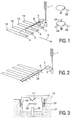
- FIG. 1 schematically represents an apparatus seen in perspective.
- FIG. 2 schematically represents a variant of the device, perspective view.
- FIG. 3 represents, on a larger scale and in section, a light emitting organ located on the ground.
- the road signaling device represented by the FIG. 1 comprises light emitting members 4, 5, 6, 7 located on the ground, coupled to optical fibers 8 connected to a power supply box 2 which introduces light into the optical fibers towards the said organs.
- a power supply box 2 which introduces light into the optical fibers towards the said organs.
- the device is located at a fire equipment level 1, so-called tricolors, intended for the regulation of circulation automobile.
- Organs 4, 5, 6, 7 emit their light mainly in the useful direction of a traffic light, that is to say in the direction indicated by arrow 9, towards the users to whom the fire is aimed.
- a pedestrian crossing is planned here, materialized by strips of paint 11, 12, 13, 14 on the floor.
- An example of realization of a member such as 4 is represented in A to right of the figure. Light is emitted from a window in direction 22.
- the power supply 2 contains a source of light which is modified in relation to the state of the fire tricolor.
- the light from this source is for example red in color, and its on / off is controlled on the basis of the state lights 1, thanks to an electrical connection 3 between the lights 1 and the housing 2.
- the red light is on when the traffic light 1 is red, and extinguished in other cases.
- the housing 2 contains multiple color light sources different.
- Those skilled in the art can easily realize, at using different color filters, mirrors and / or lenses, a device by which the light of several lamps are brought in one or more fibers optics, so as to provide a light whose color varies, each lamp being on or off related to the state of the fire (red, orange, green).
- light emitting organs can use as a source light emitting diodes located in the organs themselves.
- the organ light emitter shown in B to the right of Figure 1 has a window that emits red (or green) light in direction 23 to the attention of automobiles, during two other windows are emitting green light (or red) in directions 24, 25 for pedestrians. Separate optical fibers are then provided for populate respectively the window intended for automobiles, and those intended for pedestrians.
- an optical fiber 8 of a laterally diffusing type is used, which allows to emit light in the direction of the arrows 25 without complicated optics, along a line formed by the fiber itself.
- a reflector can be provided behind the length of fiber that crosses the street, so that favor the emission of light in the direction horizontal towards cars (arrow 25).
- Another series of light-emitting organs like 4-7 or another laterally spun, spun optical fiber in the opposite direction, can be placed at the other end of the paint strips 11, 12, 13, 14, addressing then cars arriving the other way.
- a light emitting organ located on the ground, represented in Figure 3, has an upper part which is a kind of cover 10, at least one side portion of which is transparent, and which is slightly above the ground, indicated by reference 21.
- This upper part 10 is here provided with two mirrors 17, 18, arranged back to back in wedge shape, so as to emit the light horizontally in two opposite directions, towards the users to whom the fire is aimed as well as towards those who arrive opposite.
- the figure represents a light ray which exits through the end 15 of an optical fiber, is focused by a lens 16, is reflected towards a direction horizontal by the mirror 17, and finally comes out through a part of the transparent vertical wall of the cover 10, for head in a direction indicated by reference 19.
- Light can also come from a scattering fiber lateral placed horizontally under the mirrors.
- the light emitting member can also have a single mirror, for example 17, arranged so as to emit light horizontally in one direction only, indicated by arrow 9 in figure 1, towards users to which the fire is addressed.
- the cover 10 is mounted so that it can slide down, that is to say sink into the ground when a vehicle is driving over it.
- Elastic means, here springs 20, allow it to go back up when it is released.
- the same principle can apply to the system of figure 2.
Landscapes
- Engineering & Computer Science (AREA)
- Architecture (AREA)
- Civil Engineering (AREA)
- Structural Engineering (AREA)
- Physics & Mathematics (AREA)
- General Physics & Mathematics (AREA)
- Road Signs Or Road Markings (AREA)
- Traffic Control Systems (AREA)
- Lighting Device Outwards From Vehicle And Optical Signal (AREA)
Claims (9)
- Verkehrssignalsystem mit einer Beleuchtungsvorrichtung im Boden, von der mindestens ein Beleuchtungsteil aus dem Boden herausragt und mit mindestens einer Lichtquelle verbunden ist, dadurch gekennzeichnet, daß die Vorrichtung an einer der Verkehrsregelung dienenden dreifarbigen Ampelanlage vorgesehen wird, und dadurch, daß das Beleuchtungsteil ein Licht abstrahlt, das mit dem Zustand der dreifarbigen Ampel wechselt.
- Vorrichtung nach Anspruch 1, dadurch gekennzeichnet, daß das Beleuchtungsteil das Licht vornehmlich in die Nutzrichtung der dreifarbigen Ampeln strahlt, und die Lichtquelle rot ist und leuchtet, wenn die Ampel auf rot steht, und in den anderen Fällen abgeschaltet ist.
- Vorrichtung nach Anspruch 1, dadurch gekennzeichnet, daß diese mehrere Lichtquellen verschiedener Farben umfaßt, damit die Farbe des Lichtstrahles mit der der Ampel wechselt.
- Vorrichtung nach Anspruch 3, dadurch gekennzeichnet, daß diese mindestens ein Fenster umfaßt, das ein Licht derselben Farbe wie der des Lichtes der Verkehrsampel in Richtung der Fahrzeuge strahlt, wobei mindestens ein anderes Fenster das Licht einer anderen Farbe in Richtung der Fußgänger strahlt.
- Vorrichtung nach einem beliebigen der Ansprüche 1 bis 4, dadurch gekennzeichnet, daß das Beleuchtungsteil mindestens mit einer Glasfaser an mindestens eine Lichtquelle gekoppelt ist.
- Vorrichtung nach einem beliebigen der Ansprüche 1 bis 3, dadurch gekennzeichnet, daß das Beleuchtungsteil eine Glasfaser vom seitlich abstrahlenden Typ umfaßt.
- Vorrichtung nach einem beliebigen der Ansprüche 1 bis 6, dadurch gekennzeichnet, daß das Beleuchtungsteil einen Spiegel umfaßt, der angeordnet ist, um das Licht horizontal zu den Verkehrsteilnehmern zu strahlen, an die es sich richtet.
- Vorrichtung nach einem beliebigen der Ansprüche 1 bis 6, dadurch gekennzeichnet, daß das Beleuchtungsteil Rückseite gegen Rückseite in Eckform angeordnete Spiegel umfaßt, die das Licht in zwei entgegengesetzte Richtungen abstrahlen.
- Vorrichtung nach einem beliebigen der Ansprüche 1 bis 8, dadurch gekennzeichnet, daß das Beleuchtungsteil angebracht ist, um nach unten, d.h. in den Boden gleiten zu können, wenn ein Fahrzeug darüber fährt, mit elastischen Verfahren, um, nachdem es frei ist, nach oben zurückkommen zu können.
Applications Claiming Priority (2)
| Application Number | Priority Date | Filing Date | Title |
|---|---|---|---|
| FR9614090A FR2756086A1 (fr) | 1996-11-19 | 1996-11-19 | Appareil de signalisation routiere comprenant des organes eclairants situes au sol |
| FR9614090 | 1996-11-19 |
Publications (2)
| Publication Number | Publication Date |
|---|---|
| EP0843296A1 EP0843296A1 (de) | 1998-05-20 |
| EP0843296B1 true EP0843296B1 (de) | 2002-05-08 |
Family
ID=9497765
Family Applications (1)
| Application Number | Title | Priority Date | Filing Date |
|---|---|---|---|
| EP97203530A Expired - Lifetime EP0843296B1 (de) | 1996-11-19 | 1997-11-12 | Verkehrsampel mit Beleuchtungsvorrichtungen im Boden |
Country Status (3)
| Country | Link |
|---|---|
| EP (1) | EP0843296B1 (de) |
| DE (1) | DE69712440T2 (de) |
| FR (1) | FR2756086A1 (de) |
Cited By (1)
| Publication number | Priority date | Publication date | Assignee | Title |
|---|---|---|---|---|
| FR3158777A1 (fr) * | 2024-01-29 | 2025-08-01 | Lec Societe Lyonnaise D'equipement Et De Controle | Système de signalisation lumineuse au sol |
Families Citing this family (10)
| Publication number | Priority date | Publication date | Assignee | Title |
|---|---|---|---|---|
| DE19810151B4 (de) * | 1998-03-10 | 2009-11-12 | Schubert, Hans-Joachim | Sicherheitseinrichtung und Verfahren zum Sichern eines Be- oder Entladevorgangs für Fahrzeuge an Überladebrücken |
| ES1047235Y (es) * | 2000-10-16 | 2001-08-16 | Ramos Eduardo Diz | Señalizacion luminosa para la calzada. |
| ES2191567B1 (es) * | 2002-02-25 | 2005-02-01 | Rodrigo Martin Ayala | Sistema de señalizacion vial luminosa portatil. |
| ES2427218B1 (es) * | 2012-04-27 | 2014-09-10 | Universidad Del Pais Vasco - Euskal Herriko Unibertsitatea | Sistema de aviso para seguridad vial |
| WO2017076243A1 (zh) * | 2015-11-06 | 2017-05-11 | 深圳市以捷创新科技有限公司 | 路口交通信号灯阵列驱动控制方法 |
| CN106683430A (zh) * | 2015-11-06 | 2017-05-17 | 深圳市以捷创新科技有限公司 | 智能电子警察的路口交通信号灯系统 |
| RU2620148C1 (ru) * | 2016-03-09 | 2017-05-23 | Федеральное государственное бюджетное образовательное учреждение высшего профессионального образования "Ульяновский государственный технический университет" | Система управления движением на пешеходном переходе |
| RU2621831C1 (ru) * | 2016-03-11 | 2017-06-07 | Федеральное государственное бюджетное образовательное учреждение высшего профессионального образования "Ульяновский государственный технический университет" | Регулируемое ограждение на пешеходном переходе |
| US10431079B2 (en) | 2016-03-17 | 2019-10-01 | Shenzhen Yijie Innovative Technology Co., Ltd. | Driving control apparatus for intersection traffic light array |
| DE102016216204A1 (de) * | 2016-08-29 | 2018-03-01 | Siemens Aktiengesellschaft | Bodenampel, Verfahren zum Betreiben einer Bodenampel und Verkehrsignalisierungsanordnung |
Family Cites Families (3)
| Publication number | Priority date | Publication date | Assignee | Title |
|---|---|---|---|---|
| GB2177742A (en) * | 1985-06-14 | 1987-01-28 | Sec Dep For Transport The | Vehicle pathway lane control systems |
| US4750207A (en) * | 1986-03-31 | 1988-06-07 | Siemens Hearing Instruments, Inc. | Hearing aid noise suppression system |
| EP0539615A1 (de) * | 1991-10-29 | 1993-05-05 | Daito Sangyo Co., Ltd. | Verkehrsanzeigevorrichtung und Lichtquelle für diese Anzeigevorrichtung |
-
1996
- 1996-11-19 FR FR9614090A patent/FR2756086A1/fr not_active Withdrawn
-
1997
- 1997-11-12 DE DE69712440T patent/DE69712440T2/de not_active Expired - Fee Related
- 1997-11-12 EP EP97203530A patent/EP0843296B1/de not_active Expired - Lifetime
Cited By (1)
| Publication number | Priority date | Publication date | Assignee | Title |
|---|---|---|---|---|
| FR3158777A1 (fr) * | 2024-01-29 | 2025-08-01 | Lec Societe Lyonnaise D'equipement Et De Controle | Système de signalisation lumineuse au sol |
Also Published As
| Publication number | Publication date |
|---|---|
| EP0843296A1 (de) | 1998-05-20 |
| FR2756086A1 (fr) | 1998-05-22 |
| DE69712440T2 (de) | 2003-01-09 |
| DE69712440D1 (de) | 2002-06-13 |
Similar Documents
| Publication | Publication Date | Title |
|---|---|---|
| EP0843296B1 (de) | Verkehrsampel mit Beleuchtungsvorrichtungen im Boden | |
| FR2772115A1 (fr) | Illuminateur de surface | |
| FR2936295A1 (fr) | Feux de vehicule automobile | |
| FR2761704A1 (fr) | Panneau d'avertissement | |
| EP3225905A1 (de) | Rückwärtige beleuchtungs- und/oder signalisierungsvorrichtung für kraftfahrzeug, und rücklicht zur beleuchtung und/oder signalisierung, das mit einer solchen vorrichtung ausgestattet ist | |
| FR2651358A1 (fr) | Ensemble d'affichage matriciel de caracteres graphiques et unite d'affichage pour un tel ensemble. | |
| FR3026460A1 (fr) | Systeme optique pour vehicule automobile | |
| FR2759188A1 (fr) | Dispositif de signalisation lumineuse, notamment pour regulation du trafic routier | |
| FR2579354A1 (fr) | Appareil d'affichage de caracteres | |
| US20040125612A1 (en) | Lighting system and device for automobile wheels | |
| FR2599864A1 (fr) | Dispositif pour creer un arc-en-ciel | |
| FR2660986A1 (fr) | Dispositif pour simuler un ciel etoile fixe avec un eclairage artificiel. | |
| FR2534795A1 (fr) | Dispositif d'eclairage, en particulier pour vitrines de magasins ou de salles d'exposition, ainsi que pour l'habitat | |
| FR2713747A1 (fr) | Dispositif lumineux de signalisation. | |
| FR2768492A1 (fr) | Unite de feux pour vehicules automobiles | |
| EP0984220A1 (de) | Mehrzwecksignalleuchte mit gleichmässiger Beleuchtung der Lichtscheibe | |
| CA2901937A1 (fr) | Dispositif optique pour projecteur d'eclairage et/ou de signalisation pour aeronef et projecteur comprenant un tel dispositif optique | |
| FR2851028A1 (fr) | Dispositif d'eclairage | |
| FR3115584A1 (fr) | Module d’eclairage a illumination de lentille | |
| FR2801091A1 (fr) | Dispositif d'eclairage comprenant au moins une diode electroluminescente | |
| FR2730294A1 (fr) | Dispositif permettant de collecter, vehiculer et de diffuser la lumiere du jour | |
| FR2579297A1 (fr) | Dispositif d'eclairage pour salles obscures telles que salles de cinema, theatre ou analogues | |
| FR2536649A1 (fr) | Presentoir lumineux | |
| FR2858278A3 (fr) | Dispositif d'eclairage pour une immatriculation de vehicule automobile | |
| FR2944531A1 (fr) | Plot d'eclairage. |
Legal Events
| Date | Code | Title | Description |
|---|---|---|---|
| PUAI | Public reference made under article 153(3) epc to a published international application that has entered the european phase |
Free format text: ORIGINAL CODE: 0009012 |
|
| AK | Designated contracting states |
Kind code of ref document: A1 Designated state(s): DE FR GB |
|
| RAP3 | Party data changed (applicant data changed or rights of an application transferred) |
Owner name: KONINKLIJKE PHILIPS ELECTRONICS N.V. |
|
| 17P | Request for examination filed |
Effective date: 19981120 |
|
| AKX | Designation fees paid |
Free format text: DE FR GB |
|
| RBV | Designated contracting states (corrected) |
Designated state(s): DE FR GB |
|
| GRAG | Despatch of communication of intention to grant |
Free format text: ORIGINAL CODE: EPIDOS AGRA |
|
| 17Q | First examination report despatched |
Effective date: 20010628 |
|
| GRAG | Despatch of communication of intention to grant |
Free format text: ORIGINAL CODE: EPIDOS AGRA |
|
| GRAH | Despatch of communication of intention to grant a patent |
Free format text: ORIGINAL CODE: EPIDOS IGRA |
|
| REG | Reference to a national code |
Ref country code: GB Ref legal event code: IF02 |
|
| GRAH | Despatch of communication of intention to grant a patent |
Free format text: ORIGINAL CODE: EPIDOS IGRA |
|
| GRAA | (expected) grant |
Free format text: ORIGINAL CODE: 0009210 |
|
| AK | Designated contracting states |
Kind code of ref document: B1 Designated state(s): DE FR GB |
|
| REF | Corresponds to: |
Ref document number: 69712440 Country of ref document: DE Date of ref document: 20020613 |
|
| GBT | Gb: translation of ep patent filed (gb section 77(6)(a)/1977) |
Effective date: 20020720 |
|
| REG | Reference to a national code |
Ref country code: GB Ref legal event code: 746 Effective date: 20020917 |
|
| REG | Reference to a national code |
Ref country code: FR Ref legal event code: D6 |
|
| PLBE | No opposition filed within time limit |
Free format text: ORIGINAL CODE: 0009261 |
|
| STAA | Information on the status of an ep patent application or granted ep patent |
Free format text: STATUS: NO OPPOSITION FILED WITHIN TIME LIMIT |
|
| 26N | No opposition filed |
Effective date: 20030211 |
|
| PGFP | Annual fee paid to national office [announced via postgrant information from national office to epo] |
Ref country code: GB Payment date: 20061127 Year of fee payment: 10 |
|
| PGFP | Annual fee paid to national office [announced via postgrant information from national office to epo] |
Ref country code: FR Payment date: 20061129 Year of fee payment: 10 |
|
| PGFP | Annual fee paid to national office [announced via postgrant information from national office to epo] |
Ref country code: DE Payment date: 20070110 Year of fee payment: 10 |
|
| GBPC | Gb: european patent ceased through non-payment of renewal fee |
Effective date: 20071112 |
|
| PG25 | Lapsed in a contracting state [announced via postgrant information from national office to epo] |
Ref country code: DE Free format text: LAPSE BECAUSE OF NON-PAYMENT OF DUE FEES Effective date: 20080603 |
|
| REG | Reference to a national code |
Ref country code: FR Ref legal event code: ST Effective date: 20080930 |
|
| PG25 | Lapsed in a contracting state [announced via postgrant information from national office to epo] |
Ref country code: GB Free format text: LAPSE BECAUSE OF NON-PAYMENT OF DUE FEES Effective date: 20071112 |
|
| PG25 | Lapsed in a contracting state [announced via postgrant information from national office to epo] |
Ref country code: FR Free format text: LAPSE BECAUSE OF NON-PAYMENT OF DUE FEES Effective date: 20071130 |