EP0841252A2 - Method for the manufacture of a polygon-shaped, particularly octagon-shaped container - Google Patents
Method for the manufacture of a polygon-shaped, particularly octagon-shaped container Download PDFInfo
- Publication number
- EP0841252A2 EP0841252A2 EP97116201A EP97116201A EP0841252A2 EP 0841252 A2 EP0841252 A2 EP 0841252A2 EP 97116201 A EP97116201 A EP 97116201A EP 97116201 A EP97116201 A EP 97116201A EP 0841252 A2 EP0841252 A2 EP 0841252A2
- Authority
- EP
- European Patent Office
- Prior art keywords
- polygon
- edges
- glued
- container
- cover
- Prior art date
- Legal status (The legal status is an assumption and is not a legal conclusion. Google has not performed a legal analysis and makes no representation as to the accuracy of the status listed.)
- Withdrawn
Links
Images
Classifications
-
- B—PERFORMING OPERATIONS; TRANSPORTING
- B65—CONVEYING; PACKING; STORING; HANDLING THIN OR FILAMENTARY MATERIAL
- B65D—CONTAINERS FOR STORAGE OR TRANSPORT OF ARTICLES OR MATERIALS, e.g. BAGS, BARRELS, BOTTLES, BOXES, CANS, CARTONS, CRATES, DRUMS, JARS, TANKS, HOPPERS, FORWARDING CONTAINERS; ACCESSORIES, CLOSURES, OR FITTINGS THEREFOR; PACKAGING ELEMENTS; PACKAGES
- B65D5/00—Rigid or semi-rigid containers of polygonal cross-section, e.g. boxes, cartons or trays, formed by folding or erecting one or more blanks made of paper
- B65D5/42—Details of containers or of foldable or erectable container blanks
- B65D5/64—Lids
- B65D5/68—Telescope flanged lids
-
- B—PERFORMING OPERATIONS; TRANSPORTING
- B65—CONVEYING; PACKING; STORING; HANDLING THIN OR FILAMENTARY MATERIAL
- B65D—CONTAINERS FOR STORAGE OR TRANSPORT OF ARTICLES OR MATERIALS, e.g. BAGS, BARRELS, BOTTLES, BOXES, CANS, CARTONS, CRATES, DRUMS, JARS, TANKS, HOPPERS, FORWARDING CONTAINERS; ACCESSORIES, CLOSURES, OR FITTINGS THEREFOR; PACKAGING ELEMENTS; PACKAGES
- B65D5/00—Rigid or semi-rigid containers of polygonal cross-section, e.g. boxes, cartons or trays, formed by folding or erecting one or more blanks made of paper
- B65D5/02—Rigid or semi-rigid containers of polygonal cross-section, e.g. boxes, cartons or trays, formed by folding or erecting one or more blanks made of paper by folding or erecting a single blank to form a tubular body with or without subsequent folding operations, or the addition of separate elements, to close the ends of the body
- B65D5/12—Rigid or semi-rigid containers of polygonal cross-section, e.g. boxes, cartons or trays, formed by folding or erecting one or more blanks made of paper by folding or erecting a single blank to form a tubular body with or without subsequent folding operations, or the addition of separate elements, to close the ends of the body with end closures formed separately from tubular body
Definitions
- the invention relates to a method for producing a polygon, in particular Octagon container.
- Polygon-like containers are used in large quantities for transport and Packaging of objects used.
- the invention relates above all Containers with an octagonal cross section, which are also used as pallet octagonal containers are called and consist of corrugated cardboard.
- Such containers serve the Transport of bulk goods arranged in a container Plastic bag to be transported.
- These containers are about 2 m high and have a diameter of over one meter and are therefore extreme unwieldy and difficult to manufacture.
- Telescopic corner container proposed. Because after filling, in particular The bulk material solidifies during transport, is created in the octagonal container in the upper part of an empty space, which when stacking several heavy containers one above the other would lead to the destruction of the packaging.
- Telescopic corner container is a loose polygonal part on the polygon body fixed so that there is a pressure from above on the container from Polygon body part releases. The intermediate part then slides down until the lid the packaging sits firmly on the contents.
- the octagon lower part and the octagonal intermediate part are at Telescopic corner packaging by means of a punched handle on Polygon body part connected by the handle punch in front Slip the intermediate part so that it is bent outwards manually Intermediate part settles on these handles. With a load of then these handle punches tear off or bend so that the The intermediate part slips down over the lower part.
- Such containers are manufactured in large numbers and were initially Lids and bottoms manufactured using a construction according to FEFCO 350.
- FEFCO 350 There the manual erection of lids and floors and especially the Extreme fastening of the tabs by manual gluing or stapling is complex, the construction according to FEFCO 350 has become over time completely replaced by the FEFCO 351 construction, with a Folding device the tabs of the lid are fixed.
- Disadvantage of the Construction FEFCO 351 is, however, that the inserted tabs are not fixed are and can shift under pressure. This will make the Lid larger in size and the adhesion between lid and This affects the fuselage.
- the invention has for its object a method for producing a Propose polygon, especially octagon container, which is a fast Erection enables.
- This object is achieved in that the edges of a base part automatically bent and automatically a polygon body part to create a lower part is arranged on the bottom part.
- the invention is based on the knowledge that the replacement of the construction FEFCO 350 by the construction FEFCO 351 the time to erect the Although containers could reduce further time savings with the Construction FEFCO 351 is however not achievable.
- the proposal the edges automatically fold the bottom part and create a lower part automatically arranging a polygon body part on the base part enables Use of the stable construction that has completely disappeared from the market according to FEFCO 350.
- Such an automatic production of polygon containers enables extremely quick erection with minimal personnel Expenditure.
- the edges of the bottom part are preferred glued together via bottom flaps.
- the cover part it is possible that the bottom flaps on the outside on the edges be glued on and the fuselage part is inserted into the bottom part.
- the inner ring of the lid or the bottom has a uniform shape and improves the tight fit of the lid or bottom on the polygon body.
- the tabs can also be placed on the edges from the inside be glued on and the bottom part inserted into the polygon part. This creates a uniform shape on the outside of the floor, which also ensures a firm contact with the polygon body, provided that Bottom part is inserted into the polygon part.
- edges of a cover part also automatically are folded and glued together with cover flaps and that Cover part after filling the lower part onto the lower part. Thereby the entire manufacture of the polygon container is automated to the Shorten manufacturing time even further.
- An advantageous way of connecting the polygon body and Intermediate part of the polygon provides that an open part of one of the two parts Die cut line with a straight line, preferably a grooved line, on her upper or lower end of an area is provided, and the parts be glued together on the surface.
- the provision of such Punching at the glue point has the advantage that the polygon body and Polygon intermediate part on the adhesive surface are pressed together more easily can. There is generally an air gap between the top and bottom. By the punching at the glue point creates a punching flap that follows can move inside so that the bond does not tear too soon. Furthermore can be designed so that the polygon body and Intermediate polygon can be pushed into one another without the Adhesive point detaches.
- the punched line is preferably provided on the intermediate polygon part, since this is usually placed over the polygon body and thereby the punched area is easily accessible from the outside to counter it Press polygon lower part.
- Another open Punching line is provided with another straight line Area bounded near the first area - preferably to it adjacent - is arranged. This area can be easily raised to insert an adhesive nozzle, which is under the flap between upper and Bottom slides to apply the glue.
- two parallel incisions at the bottom of the A punching flap can be created in the upper part. After putting the top over the lower part of the punching tab can be lifted slightly as a flap to advance an adhesive nozzle that injects the adhesive. Then will the tab pressed from the outside against the lower part.
- the bonding described is preferably achieved in that the Polygon body part or the polygon intermediate part with an inside Stamp is held, the edges of the bottom part or the lid part can be arranged opposite one another.
- a stamp acts as an abutment in the Container, if the edges of the base part or of the cover part are pressed. After the adhesive has set, the Stamps are removed from the container.
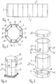
- Bottom part 5 made by folding the edges 6 to 13 upwards and are glued to one another via bottom flaps 13 to 21.
- the tabs 14 are in the bottom part to 21 glued from the inside to the edges 6 to 13 and the bottom part 5 is in the polygon body 4 used.
- a polygon intermediate part 22 is produced by a blank 23 (see FIG. 5) kinked at the creases 24 and closed by means of the adhesive tab 25 an octagonal cylinder is formed.
- the cover part 26 also made from a blank as shown in Figure 2, only that when Cover part the tabs are glued to the edges from the outside. Because of that a uniform inner surface on the cover part 26 is created Intermediate polygon part 22 inserted into the cover part 26 or the cover part 26 the polygon intermediate part 22 turned up.
- the Polygon body part 4 After creating the bottom part 5 and the polygon body part 4, the Polygon body part 4 automatically placed over the base part 5 to a lower part 27 manufacture.
- the base part 5 can also be like the cover part 26 are produced, the polygonal fuselage part 4 then preferably into the Bottom part is used.
- a polygon intermediate part 22 is then placed on the lower part 27 with grippers put on, which extends around the polygonal body part 4. So that Polygonal intermediate part 22 does not slide down, the parts are by means of Adhesive dots 28, 29 fixed to each other in the correct position. This Adhesive dots are on surfaces 28, 29 on the inside of the intermediate polygon attached, these surfaces of a U-shaped punch line 32, 33rd are limited, the area 30 and 31 respectively with a straight line 34, 35 limited.
- Figure 4 shows the finished octagonal container with the surfaces 30 and 31 with which the intermediate polygon part 22 is connected to the polygon body part 4. At a If this container is subjected to pressure from above, it slips Intermediate polygonal part 22 so far over the polygonal body part 4 until Cover part 26 rests on the filling of the container. Die cuts 32 and 33 and possibly also scoring on lines 34 and 35 ensure that the Deform surfaces 30 and 31 and, if necessary, the adhesive connection will also tear.
- the adhesive for easier application of the adhesive to the polygonal fuselage part or the Surfaces 39, 31 on the polygonal intermediate part can be a further U-shaped one Die cut line opposite the die cut lines 32 and 33 above the punched-out stamps are attached.
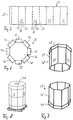
- FIGS. 6 to 8 show an octagonal blank 36 edges 37 to 44 arranged around its circumference with a polygon body 45 brought together that by automatically folding the edges 37 to 44 and gluing the edges 37 to 44 to the polygon body 45 from one Bottom part 46 and a polygon body part 45 a lower part 47 is formed.
- the polygon body is arranged by means of one in the polygon body Stamp held so that the edges 37 to 44 of the bottom part 46 after the Apply adhesive firmly to the outside of the polygon body can be pressed.
- an upper part 48 is produced by the edges of a cover part 49 be glued to the outside of an intermediate polygonal part 50.
- an H-shaped punching 51 is provided, through which the Filling opening of a sack (not shown) are led out of the container can.
- elements of the first embodiment can also be used
- Elements of the second embodiment can be combined.
- the method described enables each individual process step run automatically. This allows the entire structure of a Octagonal container or a telescopic octagonal container mechanically, without manual Work to be done.
Abstract
Description
Die Erfindung betrifft ein Verfahren zum Herstellen eines Polygon-, insbesondere Achteck-Behälters.The invention relates to a method for producing a polygon, in particular Octagon container.
Polygonartige Behälter werden in großen Stückzahlen zum Transport und zur Verpackung von Gegenständen eingesetzt. Die Erfindung betrifft jedoch vor allem Behälter mit einem achteckigen Querschnitt, die auch als Palettenachteckbehälter bezeichnet werden und aus Wellpappe bestehen. Derartige Behälter dienen dem Transport von Schüttgütern, die in einem im Behälter angeordneten Kunststoffsack transportiert werden. Diese Behälter sind etwa 2 m hoch und haben einen Durchmesser von über einem Meter und sind daher extrem unhandlich und schwer herstellbar.Polygon-like containers are used in large quantities for transport and Packaging of objects used. However, the invention relates above all Containers with an octagonal cross section, which are also used as pallet octagonal containers are called and consist of corrugated cardboard. Such containers serve the Transport of bulk goods arranged in a container Plastic bag to be transported. These containers are about 2 m high and have a diameter of over one meter and are therefore extreme unwieldy and difficult to manufacture.
Um die Stapelbarkeit befüllter Achteckbehälter zu verbessern, wurden Teleskopachteckbehälter vorgeschlagen. Da sich nach Befüllen, insbesondere während des Transports das Schüttgut verfestigt, entsteht im Achteckbehälter im oberen Teil ein Leerraum, der beim Stapeln mehrerer schwerer Behälter übereinander zur Zerstörung der Verpackung führen würde. Beim Teleskopachteckbehälter ist ein Polygonzwischenteil am Polygonrumpfteil lose fixiert, so daß es sich bei einem Druck von oben auf den Behälter vom Polygonrumpfteil löst. Das Zwischenteil rutscht danach nach unten bis der Deckel der Verpackung auf dem Füllgut fest aufsitzt.In order to improve the stackability of filled octagon containers, Telescopic corner container proposed. Because after filling, in particular The bulk material solidifies during transport, is created in the octagonal container in the upper part of an empty space, which when stacking several heavy containers one above the other would lead to the destruction of the packaging. At the Telescopic corner container is a loose polygonal part on the polygon body fixed so that there is a pressure from above on the container from Polygon body part releases. The intermediate part then slides down until the lid the packaging sits firmly on the contents.
Das Achteckunterteil und das Achteckzwischenteil werden bei Teleskopachteckverpackungen durch eine Handgriffanstanzung am Polygonrumpfteil miteinander verbunden, indem die Handgriffanstanzung vor Aufstülpen des Zwischenteils so manuell nach außen gebogen wird, daß sich das Zwischenteil auf diesen Handgriffanstanzungen absetzt. Bei einer Belastung von oben reißen dann diese Handgriffanstanzungen ab oder verbiegen sich so, daß das Zwischenteil über dem Unterteil nach unten rutscht.The octagon lower part and the octagonal intermediate part are at Telescopic corner packaging by means of a punched handle on Polygon body part connected by the handle punch in front Slip the intermediate part so that it is bent outwards manually Intermediate part settles on these handles. With a load of then these handle punches tear off or bend so that the The intermediate part slips down over the lower part.
Derartige Behälter werden in großen Stückzahlen hergestellt und zunächst wurden Deckel und Böden mittels einer Konstruktion nach FEFCO 350 hergestellt. Da das manuelle Aufrichten von Deckeln und Böden und insbesondere die Befestigung der Laschen durch manuelle Verklebung oder Heftung extrem aufwendig ist, wurde die Konstruktion nach FEFCO 350 im Laufe der Zeit vollständig durch die Konstruktion FEFCO 351 ersetzt, bei der durch eine Faltvorrichtung die Laschen des Deckels fixiert werden. Nachteilig an der Konstruktion FEFCO 351 ist jedoch, daß die eingesteckten Laschen nicht fixiert sind und sich bei einer Druckbelastung verschieben können. Dadurch wird der Deckel in seiner Abmessung größer und die Haftung zwischen Deckel und Rumpfteil wird dadurch beeinträchtigt.Such containers are manufactured in large numbers and were initially Lids and bottoms manufactured using a construction according to FEFCO 350. There the manual erection of lids and floors and especially the Extreme fastening of the tabs by manual gluing or stapling is complex, the construction according to FEFCO 350 has become over time completely replaced by the FEFCO 351 construction, with a Folding device the tabs of the lid are fixed. Disadvantage of the Construction FEFCO 351 is, however, that the inserted tabs are not fixed are and can shift under pressure. This will make the Lid larger in size and the adhesion between lid and This affects the fuselage.
Der Erfindung liegt die Aufgabe zugrunde, ein Verfahren zum Herstellen eines Polygon-, insbesondere Achteck-Behälters vorzuschlagen, das ein schnelles Aufrichten ermöglicht.The invention has for its object a method for producing a Propose polygon, especially octagon container, which is a fast Erection enables.
Diese Aufgabe wird dadurch gelöst, daß die Ränder eines Bodenteils automatisch umgeknickt und zur Erzeugung eines Unterteils automatisch ein Polygonrumpfteil am Bodenteil angeordnet wird.This object is achieved in that the edges of a base part automatically bent and automatically a polygon body part to create a lower part is arranged on the bottom part.
Der Erfindung liegt die Erkenntnis zugrunde, daß die Ersetzung der Konstruktion FEFCO 350 durch die Konstruktion FEFCO 351 die Zeit zum Aufrichten der Behälter zwar verringern konnte, eine weitere Zeiteinsparung mit der Konstruktion FEFCO 351 jedoch nicht erzielbar ist. Der Vorschlag, die Ränder des Bodenteils automatisch umzuknicken und zur Erzeugung eines Unterteils automatisch ein Polygonrumpfteil am Bodenteil anzuordnen, ermöglicht die Verwendung der vollständig vom Markt verschwundenen stabilen Konstruktion nach FEFCO 350. Eine derartige automatische Herstellung von Polygonbehältern ermöglicht eine extrem schnelle Aufrichtung bei minimalem personellen Aufwand.The invention is based on the knowledge that the replacement of the construction FEFCO 350 by the construction FEFCO 351 the time to erect the Although containers could reduce further time savings with the Construction FEFCO 351 is however not achievable. The proposal, the edges automatically fold the bottom part and create a lower part automatically arranging a polygon body part on the base part enables Use of the stable construction that has completely disappeared from the market according to FEFCO 350. Such an automatic production of polygon containers enables extremely quick erection with minimal personnel Expenditure.
Um einen Boden zu erzeugen, werden vorzugsweise die Ränder des Bodenteils über Bodenlaschen miteinander verklebt. Dasselbe gilt für das Deckelteil. Dabei ist es einerseits möglich, daß die Bodenlaschen von außen auf die Ränder aufgeklebt werden und das Rumpfteil in das Bodenteil eingesetzt wird. Dadurch hat der Innenring des Deckels bzw. des Bodens eine gleichmäßige Form und verbessert das feste Anliegen des Deckels bzw, Bodens am Polygonrumpfteil. Alternativ dazu können die Laschen aber auch von innen auf die Ränder aufgeklebt werden und das Bodenteil in das Polygonteil eingesetzt werden. Dadurch entsteht eine gleichmäßige Form der Außenseite des Bodens, die ebenfalls ein festes Anliegen an das Polygonrumpfteil gewährleistet, sofern das Bodenteil in das Polygonteil eingesetzt wird.To create a bottom, the edges of the bottom part are preferred glued together via bottom flaps. The same applies to the cover part. Here on the one hand it is possible that the bottom flaps on the outside on the edges be glued on and the fuselage part is inserted into the bottom part. Thereby the inner ring of the lid or the bottom has a uniform shape and improves the tight fit of the lid or bottom on the polygon body. Alternatively, the tabs can also be placed on the edges from the inside be glued on and the bottom part inserted into the polygon part. This creates a uniform shape on the outside of the floor, which also ensures a firm contact with the polygon body, provided that Bottom part is inserted into the polygon part.
Vorteilhaft ist es, wenn auch die Ränder eines Deckelteils automatisch umgeknickt werden und über Deckellaschen miteinander verklebt werden und das Deckelteil nach Befüllen des Unterteils aufdas Unterteil aufgesetzt wird. Dadurch wird die gesamte Herstellung des Polygonbehälters automatisiert, um die Herstellungszeit noch weiter zu verkürzen.It is advantageous if the edges of a cover part also automatically are folded and glued together with cover flaps and that Cover part after filling the lower part onto the lower part. Thereby the entire manufacture of the polygon container is automated to the Shorten manufacturing time even further.
Zur Herstellung eine Teleskopbehälters wird vorgeschlagen, daß am Polygonrumpfteil ein Polygonzwischenteil befestigt wird, indem die Teile miteinander verklebt werden. Eine Verklebung von Polygonrumpfteil und Polygonzwischenteil kann auf einfache Art und Weise automatisch erfolgen und ist somit um ein Vielfaches leichter zu automatisieren als die aus dem Stand der Technik bekannte Verbindung über eine Handlochausstanzung. Die Anzahl der Klebepunkte, ihre Fläche und die Art des Klebemittels sind dabei so festzulegen, daß die Verbindung zwischen Polygonrumpfteil und Polygonzwischenteil während der Befüllung des Behälters ausreichend fest ist und sich beim Stapeln der Behälter übereinander löst.To produce a telescopic container, it is proposed that on Polygon body part is attached to a polygon by the parts be glued together. A glue of polygon body and Intermediate polygon can be done automatically and easily is therefore much easier to automate than that from the prior art Technology known connection via a hand hole punching. The number of Glue dots, their area and the type of adhesive are to be determined that the connection between the polygon body part and polygon intermediate part during the filling of the container is sufficiently firm and when stacking the Detachable container one above the other.
Eine vorteilhafte Art der Verbindung von Polygonrumpfteil und Polygonzwischenteil sieht vor, daß an einem der beiden Teile eine offene Ausstanzlinie, die mit einer Geraden, vorzugsweise gerillten Linie, an ihrem oberen oder unteren Ende eine Fläche begrenzt, vorgesehen wird und die Teile an der Fläche miteinander verklebt werden. Das Vorsehen einer derartigen Ausstanzung an der Klebestelle hat den Vorteil, daß Polygonrumpfteil und Polygonzwischenteil an der Klebefläche leichter aufeinander gedrückt werden können. Zwischen Oberteil und Unterteil ist im allgemeinen ein Luftspalt. Durch die Anstanzung an der Klebestelle entsteht ein Anstanzungslappen, der sich nach innen bewegen kann, damit die Verklebung nicht zu früh reißt. Darüberhinaus kann die Ausstanzung auch so ausgebildet sein, daß Polygonrumpfteil und Polygonzwischenteil ineinander geschoben werden können, ohne daß sich die Klebestelle löst. An advantageous way of connecting the polygon body and Intermediate part of the polygon provides that an open part of one of the two parts Die cut line with a straight line, preferably a grooved line, on her upper or lower end of an area is provided, and the parts be glued together on the surface. The provision of such Punching at the glue point has the advantage that the polygon body and Polygon intermediate part on the adhesive surface are pressed together more easily can. There is generally an air gap between the top and bottom. By the punching at the glue point creates a punching flap that follows can move inside so that the bond does not tear too soon. Furthermore can be designed so that the polygon body and Intermediate polygon can be pushed into one another without the Adhesive point detaches.
Vorzugsweise ist die Ausstanzlinie am Polygonzwischenteil vorgesehen, da dieses üblicherweise über das Polygonrumpfteil gestülpt wird und dadurch die ausgestanzte Fläche von außen leicht zugänglich ist, um sie gegen das Polygonunterteil zu drücken.The punched line is preferably provided on the intermediate polygon part, since this is usually placed over the polygon body and thereby the punched area is easily accessible from the outside to counter it Press polygon lower part.
Um die Aufbringung des Klebstoffes zwischen Polygonunterteil und Polygonzwischenteil zu erleichtern, wird vorgeschlagen, daß eine weitere offene Ausstanzlinie vorgesehen wird, die mit einer weiteren geraden Linie eine weitere Fläche begrenzt, die in der Nähe der ersten Fläche - vorzugsweise an sie angrenzend - angeordnet ist. Diese Fläche kann leicht angehoben werden, um eine Klebstoffdüse einzufügen, die sich unter die Lasche zwischen Ober- und Unterseite schiebt, um den Klebstoff aufzubringen.To apply the adhesive between the polygon base and To facilitate polygonal part, it is proposed that another open Punching line is provided with another straight line Area bounded near the first area - preferably to it adjacent - is arranged. This area can be easily raised to insert an adhesive nozzle, which is under the flap between upper and Bottom slides to apply the glue.
Alternativ dazu kann auch durch zwei parallele Einschnitte am unteren Rand des Oberteils ein Anstanzlappen erzeugt werden. Nach Überstülpen des Oberteils über das Unterteil kann der Anstanzlappen als Lasche etwas angehoben werden, um eine Klebstoffdüse vorzuschieben, die den Klebstoff einspritzt. Anschließend wird die Lasche von außen gegen das Unterteil gedrückt.Alternatively, two parallel incisions at the bottom of the A punching flap can be created in the upper part. After putting the top over the lower part of the punching tab can be lifted slightly as a flap to advance an adhesive nozzle that injects the adhesive. Then will the tab pressed from the outside against the lower part.
Während bei den bisher beschriebenen Verfahren die Ränder des Bodenteils über Bodenlaschen und die Ränder des Deckelteils über Deckellaschen miteinander verklebt werden, wird als Alternative vorgeschlagen, daß die Ränder des Bodenteils bzw. des Deckelteils automatisch an die Außenseite des Polygonrumpfteils bzw. des Polygonzwischenteils geklebt werden. Bei diesem Verfahren wird nicht mehr zunächst ein in sich stabiles Bodenteil hergestellt, in das anschließend das Polygonrumpfteil eingesetzt wird, sondern das Unterteil wird dadurch erzeugt, daß Laschen am Zuschnitt eines Bodenteils umgeknickt und direkt am Polygonrumpfteil festgeklebt werden. Da das Bodenteil und ggf. das Deckelteil nicht mehr in sich selbst stabil hergestellt werden müssen, wird weniger Materialaufwand für den Zuschnitt des Boden bzw. des Deckelteils benötigt und der Umfang des gesamten Behälters verringert sich, da nicht mehr Laschen auf Ränder geklebt werden müssen.While in the processes described so far, the edges of the bottom part over Bottom flaps and the edges of the lid part together via lid flaps be glued, it is proposed as an alternative that the edges of the Bottom part or the lid part automatically to the outside of the Polygon body part or the polygon intermediate part are glued. With this The process is no longer first of all producing a stable base part, in then the polygon body is used, but the lower part is generated by folding tabs on the cut of a bottom part and glued directly to the polygon body. Since the bottom part and possibly the lid part will no longer have to be made stable in itself less material for cutting the bottom or the cover part needed and the size of the entire container is reduced because no more Tabs need to be glued to edges.
Vorzugsweise wird die beschriebene Verklebung dadurch erreicht, daß das Polygonrumpfteil bzw. das Polygonzwischenteil mit einem innenliegenden Stempel gehalten wird, der den Rändern des Bodenteils bzw. des Deckelteils gegenüberliegend anordbar ist. Ein derartiger Stempel wirkt als Widerlager im Behälter, wenn nach Aufbringung von Klebstoff die Ränder des Bodenteils bzw. des Deckelteils angedrückt werden. Nach Abbinden des Klebstoffes kann der Stempel wieder aus dem Behälter entfernt werden.The bonding described is preferably achieved in that the Polygon body part or the polygon intermediate part with an inside Stamp is held, the edges of the bottom part or the lid part can be arranged opposite one another. Such a stamp acts as an abutment in the Container, if the edges of the base part or of the cover part are pressed. After the adhesive has set, the Stamps are removed from the container.
Da für viele Anwendungen von Achteckbehältern im Achteck-Behälter ein Füllsack angeordnet werden muß und die Anordnung des Füllsackes gerade bei einer automatischen Behälterherstellung zu Schwierigkeiten führen kann, wird vorgeschlagen, daß in einem Deckelteil des Polygonbehälters eine H-Stanzung angebracht wird und ein Sack so durch die Stanzung gezogen wird, daß der Sack innerhalb des Polygonbehälters liegt und seine Füllöffnung außerhalb. Dies ermöglicht es, den Polygonbehälter zuerst vollständig mit innenliegendem Füllsack und aufgebrachtem Deckel herzustellen und erst danach zu befüllen. An der Füllmaschine kann dann der Füllrüssel in die herausragende Füllsacköffnung gesteckt werden, um die Befüllung des Behälters durchzuführen. Anschließend wird die Füllsacköffnung beispielsweise mittels eines Kunststoffbandes verschlossen und kann dann in die H-Öffnung eingedrückt werden. Dieses Füllverfahren hat den großen Vorteil, daß sichergestellt wird, daß keine Fremdkörper beim Einfüllen mit in den Füllsack gelangen.As for many uses of octagon containers in the octagon container Filling bag must be arranged and the arrangement of the filling bag straight at an automatic container production can lead to difficulties proposed that in a cover part of the polygonal container an H-punching is attached and a sack is pulled through the punching so that the sack lies inside the polygon container and its filling opening outside. This makes it possible to completely fill the polygon container with the inside Make the filling bag and the applied lid and only fill afterwards. On the filling machine can then fill the proboscis into the protruding filling bag opening be inserted to carry out the filling of the container. Subsequently the filling bag opening is, for example, by means of a plastic tape closed and can then be pressed into the H-opening. This The filling process has the great advantage of ensuring that none Foreign objects get into the filling bag when filling.
Zwei Ausführungsbeispiele der Erfindung sind in der Zeichnung dargestellt und werden im folgenden näher beschrieben.Two embodiments of the invention are shown in the drawing and are described in more detail below.
Es zeigt,
- Figur 1
- einen Zuschnitt für ein Polygonrumpfteil
Figur 2- einen Zuschnitt für ein Bodenteil
- Figur 3
- die Einzelelemente eines Achteckbehälters
Figur 4- einen Achteckbehälter auf einer Palette
Figur 5- einen Zuschnitt für ein Polygonzwischenteil
Figur 6- einen alternativen Zuschnitt für ein Deckel- oder Bodenteil
Figur 7- die Elemente eines alternativen Achteckbehälters und
Figur 8- den alternativen Achteckbehälter auf einer Palette.
- Figure 1
- a blank for a polygon body
- Figure 2
- a cut for a bottom part
- Figure 3
- the individual elements of an octagon container
- Figure 4
- an octagon container on a pallet
- Figure 5
- a blank for an intermediate polygon
- Figure 6
- an alternative cut for a lid or base part
- Figure 7
- the elements of an alternative octagon container and
- Figure 8
- the alternative octagon container on a pallet.
Aus dem in Figur 1 dargestellten Zuschnitt 1 wird zunächst durch Faltung an den
Knickkanten 2 und Verklebung mittels der Klebelasche 3 ein achteckiger Zylinder
gefertigt, der als Polygonrumpfteil 4 (vergl. Figur 3) dient.From the blank 1 shown in Figure 1 is first by folding to the
Buckling
Parallel dazu oder anschließend wird aus einem Zuschnitt nach Figur 2 ein
Bodenteil 5 hergestellt, indem die Ränder 6 bis 13 nach oben geknickt werden
und über Bodenlaschen 13 bis 21 miteinander verklebt werden.In parallel with or subsequently, a blank according to FIG. 2 is used
Wie aus den Figuren 3 und 4 ersichtlich, werden beim Bodenteil die Laschen 14
bis 21 von innen auf die Ränder 6 bis 13 aufgeklebt und das Bodenteil 5 wird in
das Polygonrumpfteil 4 eingesetzt.As can be seen from FIGS. 3 and 4, the
Weiterhin wird ein Polygonzwischenteil 22 hergestellt, indem ein Zuschnitt 23
(vgl. Figur 5) an den Rillungen 24 geknickt und mittels der Klebelasche 25 zu
einem achteckigen Zylinder geformt wird. Nach Figur 3 ist das Deckelteil 26
ebenfalls aus einem Zuschnitt wie in Figur 2 gezeigt, erstellt, nur daß beim
Deckelteil die Laschen von außen auf die Ränder aufgeklebt sind. Da dadurch
eine gleichmäßige Innenfläche am Deckelteil 26 entsteht, wird das
Polygonzwischenteil 22 in das Deckelteil 26 eingesetzt bzw. das Deckelteil 26 auf
das Polygonzwischenteil 22 gestülpt.Furthermore, a polygon
Nach Erstellung des Bodenteils 5 und des Polygonrumpfteiles 4 wird das
Polygonrumpfteil 4 über das Bodenteil 5 automatisch gestülpt, um ein Unterteil
27 herzustellen. Alternativ kann auch das Bodenteil 5 wie das Deckelteil 26
hergestellt werden, wobei dann das polygone Rumpfteil 4 vorzugsweise in das
Bodenteil eingesetzt wird. After creating the
Auf das Unterteil 27 wird dann mit Greifern ein Polygonzwischenteil 22
aufgesetzt, das um das polygone Rumpfteil 4 herumreicht. Damit das
Polygonzwischenteil 22 nicht herunterrutscht, werden die Teile mittels
Klebepunkten 28, 29 in der richtigen Position aneinander fixiert. Diese
Klebepunkte sind auf Flächen 28, 29 an den Innenseiten des Polygonzwischenteils
angebracht, wobei diese Flächen von einer U-förmigen Ausstanzlinie 32, 33
begrenzt sind, die mit einer geraden Linie 34, 35 die Fläche 30 bzw. 31
begrenzt.A polygon
In Figur 3 sind nur zwei Klebepunkten 28, 29 auf ihren entsprechenden Flächen
gezeigt. Der Figur 5 ist jedoch zu entnehmen, daß die Klebepunkte und die
Flächen gleichmäßig verteilt um den Umfang des polygonen Zwischenteils herum
angeordnet sind.In Figure 3 there are only two
Figur 4 zeigt den fertigen Achteckbehälter mit den Flächen 30 und 31, mit denen
das Polygonzwischenteil 22 mit dem Polygonrumpfteil 4 verbunden ist. Bei einer
Belastung dieses Behälters durch einen Druck von oben, rutscht das
Polygonzwischenteil 22 soweit über das Polygonrumpfteil 4 nach unten bis das
Deckelteil 26 auf der Befüllung des Behälters aufliegt. Die Stanzungen 32 und 33
und ggf. auch eine Rillung auf den Linien 34 und 35 sorgen dafür, daß sich die
Flächen 30 und 31 verformen und ggf. auch die Klebeverbindung reißt.Figure 4 shows the finished octagonal container with the
Zum einfacheren Aufbringen des Klebstoffs auf das polygone Rumpfteil oder die
Flächen 39, 31 am polygonen Zwischenteil kann eine weitere U-förmige
Ausstanzlinie entgegengesetzt zu den Ausstanzlinien 32 und 33 oberhalb der
eingezeichneten Ausstanzungen angebracht werden. For easier application of the adhesive to the polygonal fuselage part or the
Eine weitere Möglichkeit zur automatischen Herstellung eines Achteckbehälters
zeigen die Figuren 6 bis 8. Hierbei wird ein achteckiger Zuschnitt 36 mit an
seinem Umfang angeordneten Rändern 37 bis 44 so mit einem Polygonrumpfteil
45 zusammengebracht, daß durch automatisches Umknicken der Ränder 37 bis
44 und Ankleben der Ränder 37 bis 44 an das Polygonrumpfteil 45 aus einem
Bodenteil 46 und einem Polygonrumpfteil 45 ein Unterteil 47 entsteht. Das
Polygonrumpfteil wird dabei mittels eines im Polygonrumpfteil angeordneten
Stempels so gehalten, daß die Ränder 37 bis 44 des Bodenteils 46 nach der
Auftragung von Klebstoff fest an die Außenseite des Polygonrumpfteils
angedrückt werden können.Another possibility for the automatic production of an octagon container
FIGS. 6 to 8 show an octagonal blank 36
Analog wird ein Oberteil 48 hergestellt, indem die Ränder eines Deckelteils 49
an die Außenseite eines Polygonzwischenteils 50 angeklebt werden.Analogously, an
Im Deckelteil 49 ist eine H-förmige Ausstanzung 51 vorgesehen, durch die die
Füllöffnung eines Sackes (nicht gezeigt) aus dem Behälter herausgeführt werden
kann. Somit kann ein in das Oberteil 48 eingeführter Sack nach der Verklebung
des Oberteils 48 mit dem Unterteil 47 durch die sich in der H-Stanzung
befindliche Füllöffnung des Sackes befüllt werden.In the
Verständlicherweise können auch Elemente des ersten Ausführungsbeispiels mit
Elementen des zweiten Ausführungsbeispiels kombiniert werden. Beispielsweise
kann ein Unterteil 27, das entsprechend dem ersten Ausführungsbeispiel
hergestellt wurde mit einem Oberteil 48, das nach dem zweiten
Ausführungsbeispiel hergestellt wurde, verklebt werden. Understandably, elements of the first embodiment can also be used
Elements of the second embodiment can be combined. For example
can be a
Das beschriebene Verfahren ermöglicht es, jeden einzelnen Verfahrensgang automatisch auszuführen. Dadurch kann der gesamte Aufbau eines Achteckbehälters oder eines Teleskopachteckbehälters maschinell, ohne manuelle Arbeit durchgeführt werden.The method described enables each individual process step run automatically. This allows the entire structure of a Octagonal container or a telescopic octagonal container mechanically, without manual Work to be done.
Claims (12)
Applications Claiming Priority (4)
| Application Number | Priority Date | Filing Date | Title |
|---|---|---|---|
| DE19646173 | 1996-11-08 | ||
| DE19646173 | 1996-11-08 | ||
| DE19651199 | 1996-12-10 | ||
| DE19651199A DE19651199A1 (en) | 1996-11-08 | 1996-12-10 | Method for producing a polygon, in particular octagon, container |
Publications (2)
| Publication Number | Publication Date |
|---|---|
| EP0841252A2 true EP0841252A2 (en) | 1998-05-13 |
| EP0841252A3 EP0841252A3 (en) | 1998-11-11 |
Family
ID=26031111
Family Applications (1)
| Application Number | Title | Priority Date | Filing Date |
|---|---|---|---|
| EP97116201A Withdrawn EP0841252A3 (en) | 1996-11-08 | 1997-09-18 | Method for the manufacture of a polygon-shaped, particularly octagon-shaped container |
Country Status (1)
| Country | Link |
|---|---|
| EP (1) | EP0841252A3 (en) |
Cited By (4)
| Publication number | Priority date | Publication date | Assignee | Title |
|---|---|---|---|---|
| JP5514937B1 (en) * | 2013-07-16 | 2014-06-04 | ヤマトパッキングサービス株式会社 | Packing box |
| ES2544493A1 (en) * | 2014-02-28 | 2015-08-31 | Tecnicartón, S.L. | Cover for container (Machine-translation by Google Translate, not legally binding) |
| WO2017197592A1 (en) * | 2016-05-18 | 2017-11-23 | 深圳市沃特沃德股份有限公司 | Dual-purpose pet food packing box |
| WO2019141887A1 (en) | 2018-01-18 | 2019-07-25 | Telesforo González Maquinaria, Slu | Reinforced polygonal container made of glued corrugated laminar material, production method and machine for forming same |
Family Cites Families (6)
| Publication number | Priority date | Publication date | Assignee | Title |
|---|---|---|---|---|
| US3283673A (en) * | 1964-03-26 | 1966-11-08 | Waldorf Paper Prod Co | Apparatus for forming bulk packages |
| GB1389951A (en) * | 1972-12-21 | 1975-04-09 | Ashton Containers | Transportable container |
| US4186865A (en) * | 1978-06-13 | 1980-02-05 | International Drum Corporation | Means for securing the bottom closure of a polygonal container |
| DE7819146U1 (en) * | 1978-06-26 | 1978-11-09 | Basf Ag | Corrugated cardboard container or the like |
| GB2037711B (en) * | 1978-11-24 | 1982-10-06 | Walton D | Containers |
| FR2598684B1 (en) * | 1986-05-14 | 1990-11-23 | Socar | NEW FOLDABLE PACKAGING, OF THE PALLET CASE TYPE, OF WHICH THE POLYGON-SHAPED SECTION HAS A SYMMETRY PLAN |
-
1997
- 1997-09-18 EP EP97116201A patent/EP0841252A3/en not_active Withdrawn
Non-Patent Citations (1)
| Title |
|---|
| None |
Cited By (5)
| Publication number | Priority date | Publication date | Assignee | Title |
|---|---|---|---|---|
| JP5514937B1 (en) * | 2013-07-16 | 2014-06-04 | ヤマトパッキングサービス株式会社 | Packing box |
| ES2544493A1 (en) * | 2014-02-28 | 2015-08-31 | Tecnicartón, S.L. | Cover for container (Machine-translation by Google Translate, not legally binding) |
| WO2017197592A1 (en) * | 2016-05-18 | 2017-11-23 | 深圳市沃特沃德股份有限公司 | Dual-purpose pet food packing box |
| WO2019141887A1 (en) | 2018-01-18 | 2019-07-25 | Telesforo González Maquinaria, Slu | Reinforced polygonal container made of glued corrugated laminar material, production method and machine for forming same |
| EP3616896A4 (en) * | 2018-01-18 | 2020-11-25 | Telesforo González Maquinaria, SLU | Reinforced polygonal container made of glued corrugated laminar material, production method and machine for forming same |
Also Published As
| Publication number | Publication date |
|---|---|
| EP0841252A3 (en) | 1998-11-11 |
Similar Documents
| Publication | Publication Date | Title |
|---|---|---|
| EP3439977B1 (en) | Package sleeve, package and method for producing a package | |
| EP0260345A2 (en) | Packaging unit with several cardboard boxes | |
| DE4035352C2 (en) | Device for producing boxes with a hinged lid and collar and for filling these boxes | |
| DE20316996U1 (en) | Cut from kraft cardboard to produce a multi-row bottle carrier | |
| CH629437A5 (en) | Carton, method for its manufacture, and blank for carrying out the method | |
| EP0038488B1 (en) | Method for manufacturing a liquid-tight container | |
| DE2226071A1 (en) | BOWL-SHAPED CONTAINER WITH PARTITION WALL | |
| EP0041924B1 (en) | Method of manufacturing a deformable container and deformable container | |
| DE3133258C2 (en) | ||
| EP0218186B1 (en) | Box made of cardboard, corrugated cardboard or the like | |
| DE2231262A1 (en) | PACKAGING CONTAINER AND METHOD FOR MANUFACTURING IT | |
| EP0841252A2 (en) | Method for the manufacture of a polygon-shaped, particularly octagon-shaped container | |
| DE3029002A1 (en) | SUPPORTING DEVICE FOR VESSELS HAVING SIDE-CROWNING FRONT PARTS AND CUTTING THEREFOR | |
| DE2720907A1 (en) | TUBE-LIKE CONTAINER AND METHOD OF FILLING AND MANUFACTURING A TUBE-LIKE CONTAINER | |
| WO2008009501A2 (en) | Method and device for producing a highly precise box | |
| EP0592939B1 (en) | Method and device for producing of a multifunction packaging | |
| DE19651199A1 (en) | Method for producing a polygon, in particular octagon, container | |
| DE4438076C2 (en) | Can and method of making a can | |
| EP0654413B1 (en) | Bottle packaging | |
| DE202012006513U1 (en) | Bottle carrier in the form of bottleneck cuffs made of different cardboard material as a packaging unit with high carrying stability properties | |
| CH537321A (en) | Packaging, especially for biscuits | |
| DE2031221C (en) | Device for sealing a package tightly | |
| DE10060604A1 (en) | Machine-carrying device for bottles | |
| EP1657164A1 (en) | Package and method for its production | |
| DE8306674U1 (en) | Bottle packaging |
Legal Events
| Date | Code | Title | Description |
|---|---|---|---|
| PUAI | Public reference made under article 153(3) epc to a published international application that has entered the european phase |
Free format text: ORIGINAL CODE: 0009012 |
|
| AK | Designated contracting states |
Kind code of ref document: A2 Designated state(s): BE DE FR NL |
|
| AX | Request for extension of the european patent |
Free format text: AL;LT;LV;RO;SI |
|
| PUAL | Search report despatched |
Free format text: ORIGINAL CODE: 0009013 |
|
| AK | Designated contracting states |
Kind code of ref document: A3 Designated state(s): AT BE CH DE DK ES FI FR GB GR IE IT LI LU MC NL PT SE |
|
| AX | Request for extension of the european patent |
Free format text: AL;LT;LV;RO;SI |
|
| 17P | Request for examination filed |
Effective date: 19990430 |
|
| AKX | Designation fees paid |
Free format text: BE DE FR NL |
|
| STAA | Information on the status of an ep patent application or granted ep patent |
Free format text: STATUS: THE APPLICATION IS DEEMED TO BE WITHDRAWN |
|
| 18D | Application deemed to be withdrawn |
Effective date: 20000401 |