EP0841199A2 - Pneumatic tyre - Google Patents
Pneumatic tyre Download PDFInfo
- Publication number
- EP0841199A2 EP0841199A2 EP19970307114 EP97307114A EP0841199A2 EP 0841199 A2 EP0841199 A2 EP 0841199A2 EP 19970307114 EP19970307114 EP 19970307114 EP 97307114 A EP97307114 A EP 97307114A EP 0841199 A2 EP0841199 A2 EP 0841199A2
- Authority
- EP
- European Patent Office
- Prior art keywords
- sub
- circumferential
- groove
- grooves
- axial
- Prior art date
- Legal status (The legal status is an assumption and is not a legal conclusion. Google has not performed a legal analysis and makes no representation as to the accuracy of the status listed.)
- Granted
Links
Images


Classifications
-
- B—PERFORMING OPERATIONS; TRANSPORTING
- B60—VEHICLES IN GENERAL
- B60C—VEHICLE TYRES; TYRE INFLATION; TYRE CHANGING; CONNECTING VALVES TO INFLATABLE ELASTIC BODIES IN GENERAL; DEVICES OR ARRANGEMENTS RELATED TO TYRES
- B60C11/00—Tyre tread bands; Tread patterns; Anti-skid inserts
- B60C11/03—Tread patterns
- B60C11/13—Tread patterns characterised by the groove cross-section, e.g. for buttressing or preventing stone-trapping
-
- B—PERFORMING OPERATIONS; TRANSPORTING
- B60—VEHICLES IN GENERAL
- B60C—VEHICLE TYRES; TYRE INFLATION; TYRE CHANGING; CONNECTING VALVES TO INFLATABLE ELASTIC BODIES IN GENERAL; DEVICES OR ARRANGEMENTS RELATED TO TYRES
- B60C11/00—Tyre tread bands; Tread patterns; Anti-skid inserts
- B60C11/03—Tread patterns
- B60C11/0306—Patterns comprising block rows or discontinuous ribs
- B60C11/0309—Patterns comprising block rows or discontinuous ribs further characterised by the groove cross-section
-
- B—PERFORMING OPERATIONS; TRANSPORTING
- B60—VEHICLES IN GENERAL
- B60C—VEHICLE TYRES; TYRE INFLATION; TYRE CHANGING; CONNECTING VALVES TO INFLATABLE ELASTIC BODIES IN GENERAL; DEVICES OR ARRANGEMENTS RELATED TO TYRES
- B60C11/00—Tyre tread bands; Tread patterns; Anti-skid inserts
- B60C11/03—Tread patterns
- B60C11/12—Tread patterns characterised by the use of narrow slits or incisions, e.g. sipes
- B60C11/1236—Tread patterns characterised by the use of narrow slits or incisions, e.g. sipes with special arrangements in the tread pattern
- B60C11/125—Tread patterns characterised by the use of narrow slits or incisions, e.g. sipes with special arrangements in the tread pattern arranged at the groove bottom
-
- B—PERFORMING OPERATIONS; TRANSPORTING
- B60—VEHICLES IN GENERAL
- B60C—VEHICLE TYRES; TYRE INFLATION; TYRE CHANGING; CONNECTING VALVES TO INFLATABLE ELASTIC BODIES IN GENERAL; DEVICES OR ARRANGEMENTS RELATED TO TYRES
- B60C11/00—Tyre tread bands; Tread patterns; Anti-skid inserts
- B60C11/03—Tread patterns
- B60C11/12—Tread patterns characterised by the use of narrow slits or incisions, e.g. sipes
- B60C11/1259—Depth of the sipe
- B60C11/1263—Depth of the sipe different within the same sipe
-
- B—PERFORMING OPERATIONS; TRANSPORTING
- B60—VEHICLES IN GENERAL
- B60C—VEHICLE TYRES; TYRE INFLATION; TYRE CHANGING; CONNECTING VALVES TO INFLATABLE ELASTIC BODIES IN GENERAL; DEVICES OR ARRANGEMENTS RELATED TO TYRES
- B60C11/00—Tyre tread bands; Tread patterns; Anti-skid inserts
- B60C11/03—Tread patterns
- B60C11/13—Tread patterns characterised by the groove cross-section, e.g. for buttressing or preventing stone-trapping
- B60C11/1307—Tread patterns characterised by the groove cross-section, e.g. for buttressing or preventing stone-trapping with special features of the groove walls
- B60C11/1315—Tread patterns characterised by the groove cross-section, e.g. for buttressing or preventing stone-trapping with special features of the groove walls having variable inclination angles, e.g. warped groove walls
-
- B—PERFORMING OPERATIONS; TRANSPORTING
- B60—VEHICLES IN GENERAL
- B60C—VEHICLE TYRES; TYRE INFLATION; TYRE CHANGING; CONNECTING VALVES TO INFLATABLE ELASTIC BODIES IN GENERAL; DEVICES OR ARRANGEMENTS RELATED TO TYRES
- B60C11/00—Tyre tread bands; Tread patterns; Anti-skid inserts
- B60C11/03—Tread patterns
- B60C11/13—Tread patterns characterised by the groove cross-section, e.g. for buttressing or preventing stone-trapping
- B60C11/1369—Tie bars for linking block elements and bridging the groove
-
- B—PERFORMING OPERATIONS; TRANSPORTING
- B60—VEHICLES IN GENERAL
- B60C—VEHICLE TYRES; TYRE INFLATION; TYRE CHANGING; CONNECTING VALVES TO INFLATABLE ELASTIC BODIES IN GENERAL; DEVICES OR ARRANGEMENTS RELATED TO TYRES
- B60C15/00—Tyre beads, e.g. ply turn-up or overlap
- B60C15/06—Flipper strips, fillers, or chafing strips and reinforcing layers for the construction of the bead
- B60C15/0603—Flipper strips, fillers, or chafing strips and reinforcing layers for the construction of the bead characterised by features of the bead filler or apex
- B60C15/0607—Flipper strips, fillers, or chafing strips and reinforcing layers for the construction of the bead characterised by features of the bead filler or apex comprising several parts, e.g. made of different rubbers
-
- B—PERFORMING OPERATIONS; TRANSPORTING
- B60—VEHICLES IN GENERAL
- B60C—VEHICLE TYRES; TYRE INFLATION; TYRE CHANGING; CONNECTING VALVES TO INFLATABLE ELASTIC BODIES IN GENERAL; DEVICES OR ARRANGEMENTS RELATED TO TYRES
- B60C9/00—Reinforcements or ply arrangement of pneumatic tyres
- B60C9/18—Structure or arrangement of belts or breakers, crown-reinforcing or cushioning layers
- B60C9/20—Structure or arrangement of belts or breakers, crown-reinforcing or cushioning layers built-up from rubberised plies each having all cords arranged substantially parallel
- B60C9/2003—Structure or arrangement of belts or breakers, crown-reinforcing or cushioning layers built-up from rubberised plies each having all cords arranged substantially parallel characterised by the materials of the belt cords
- B60C9/2006—Structure or arrangement of belts or breakers, crown-reinforcing or cushioning layers built-up from rubberised plies each having all cords arranged substantially parallel characterised by the materials of the belt cords consisting of steel cord plies only
-
- B—PERFORMING OPERATIONS; TRANSPORTING
- B60—VEHICLES IN GENERAL
- B60C—VEHICLE TYRES; TYRE INFLATION; TYRE CHANGING; CONNECTING VALVES TO INFLATABLE ELASTIC BODIES IN GENERAL; DEVICES OR ARRANGEMENTS RELATED TO TYRES
- B60C11/00—Tyre tread bands; Tread patterns; Anti-skid inserts
- B60C11/03—Tread patterns
- B60C11/12—Tread patterns characterised by the use of narrow slits or incisions, e.g. sipes
- B60C11/1204—Tread patterns characterised by the use of narrow slits or incisions, e.g. sipes with special shape of the sipe
- B60C2011/1213—Tread patterns characterised by the use of narrow slits or incisions, e.g. sipes with special shape of the sipe sinusoidal or zigzag at the tread surface
-
- B—PERFORMING OPERATIONS; TRANSPORTING
- B60—VEHICLES IN GENERAL
- B60C—VEHICLE TYRES; TYRE INFLATION; TYRE CHANGING; CONNECTING VALVES TO INFLATABLE ELASTIC BODIES IN GENERAL; DEVICES OR ARRANGEMENTS RELATED TO TYRES
- B60C11/00—Tyre tread bands; Tread patterns; Anti-skid inserts
- B60C11/03—Tread patterns
- B60C11/12—Tread patterns characterised by the use of narrow slits or incisions, e.g. sipes
- B60C11/1236—Tread patterns characterised by the use of narrow slits or incisions, e.g. sipes with special arrangements in the tread pattern
- B60C2011/1254—Tread patterns characterised by the use of narrow slits or incisions, e.g. sipes with special arrangements in the tread pattern with closed sipe, i.e. not extending to a groove
-
- Y—GENERAL TAGGING OF NEW TECHNOLOGICAL DEVELOPMENTS; GENERAL TAGGING OF CROSS-SECTIONAL TECHNOLOGIES SPANNING OVER SEVERAL SECTIONS OF THE IPC; TECHNICAL SUBJECTS COVERED BY FORMER USPC CROSS-REFERENCE ART COLLECTIONS [XRACs] AND DIGESTS
- Y10—TECHNICAL SUBJECTS COVERED BY FORMER USPC
- Y10S—TECHNICAL SUBJECTS COVERED BY FORMER USPC CROSS-REFERENCE ART COLLECTIONS [XRACs] AND DIGESTS
- Y10S152/00—Resilient tires and wheels
- Y10S152/03—Slits in threads
-
- Y—GENERAL TAGGING OF NEW TECHNOLOGICAL DEVELOPMENTS; GENERAL TAGGING OF CROSS-SECTIONAL TECHNOLOGIES SPANNING OVER SEVERAL SECTIONS OF THE IPC; TECHNICAL SUBJECTS COVERED BY FORMER USPC CROSS-REFERENCE ART COLLECTIONS [XRACs] AND DIGESTS
- Y10—TECHNICAL SUBJECTS COVERED BY FORMER USPC
- Y10S—TECHNICAL SUBJECTS COVERED BY FORMER USPC CROSS-REFERENCE ART COLLECTIONS [XRACs] AND DIGESTS
- Y10S152/00—Resilient tires and wheels
- Y10S152/902—Non-directional tread pattern having no circumferential rib and having blocks defined by circumferential grooves and transverse grooves
Abstract
Description
- The present invention relates to a pneumatic tyre having an improved tread portion.
- For heavy duty vehicles such as trucks, buses and the like so called all-weather tyres are preferred recently. In general, to improve on-the-snow/ice performance, the tread portion of such an all-weather tyre is divided into blocks which are weak in comparison with a rib. Thus, the tyre suffers from uneven wear such as heel-and-toe wear during running.
- In the published Japanese application No. JP-B2-57-9967, a heavy duty tyre is disclosed, wherein, to increase the uneven wear resistance of the tread blocks, each axial groove between the blocks is partially provided with platforms. Each platform protrudes from one of the groove sidewalls, to a small distance from the opposite platform. This means however, does not fully control the movement of the blocks during running, and thus uneven wear is not effectively decreased.
- It is an object of the present invention to provide a pneumatic tyre in which uneven wear is effectively prevented without sacrificing other performances such as on-the-snow/ice performance and the resistance to cracking and rubber tearing-off.
- According to one aspect of the present invention, a pneumatic tyre comprises a tread portion provided with at least two main grooves extending circumferentially of the tyre to axially divided the tread portion into three land portions, at least one of the three land portions provided with sub-grooves shallower in depth than the main grooves, the sub-grooves having a width in the range of from 0.05 to 0.60 times the width of the main grooves, the sub-grooves comprising axial sub-grooves extending across the land portion and a circumferential sub-groove extending continuously in the circumferential direction of the tyre, the circumferential sub-groove provided in the bottom with a circumferential sipe extending continuously in the circumferential direction of the tyre, each of the axial sub-grooves provided in the groove bottom on each side of the circumferential sub-groove with an axial sipe extending along the longitudinal direction thereof, the axial sipe having a first end on the circumferential sub-groove side and a second end on another side, the first end not intersecting the circumferential sipe and closed within the groove bottom.
- Preferably, the second end is closed within the groove bottom.
- Embodiments of the present invention will now be described in detail in conjunction with the accompanying drawings:
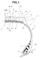
- Fig.1 is a cross sectional view of a tyre showing an embodiment of the present invention;
- Fig.2 is a plan view thereof showing an example of the tread pattern;
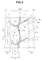
- Fig.3 is an enlarged plan view showing a rib-like land portion provided with sub-grooves;
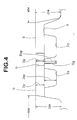
- Fig.4 is a cross sectional view taken along a line I-I in Fig.3;
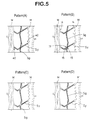
- Fig.5 shows tread patterns (A) to (D) used in comparison tests as of Ref. tyres 1 to 4, respectively; and
- Fig.6 is a plan view showing another example of the tread pattern.
- In the Figures, the pneumatic tyre 1 is an all-weather block pattern radial tyre for heavy duty vehicles.
- The tyre comprises a
tread portion 2, a pair of axially spacedbead portions 4 with abead core 5 therein, a pair ofsidewall portions 3 extending radially inwardly from the tread edges to the bead portions, atoroidal carcass 6 extending between thebead portions 4 and abelt 7 disposed radially outside the carcass and inside thetread portion 2. - The
carcass 6 comprises at least one, in this example only one, ply of cords arranged radially at an angle of from 90 to 75 degrees with respect to the tyre equator C, extending between thebead portions 4 through thetread portion 2 andsidewall portions 3, and turned up around thebead cores 5. The carcass turned upportion 6a in each bead terminates above thebead core 5 and below the tyre maximum width position. Between each turned upportion 6a and themain portion 6b of the carcass, abead apex rubber 8 which extends and tapers radially outwardly from thebead core 5 is disposed to reinforce thebead portion 4. - For the carcass cords, steel cords are used in this example, but organic fibre cords, e.g polyester, rayon, nylon, and the like may be used. When only organic cords are used, it is preferable to use two or more carcass plies.
- The
belt 7 comprises a plurality of plies, in this example four plies, of parallel cords laid at an angle of from 15 to 80 degrees with respect to the tyre equator C. The cord angle and cord inclining direction of each ply is differed from the adjacent plies so that the cords of each ply cross the cords of the adjacent plies. - For the belt cords, steel cords are used in this example, but high modulus organic fibre cords such as aromatic polyamide cords may be used.
- The
tread portion 2 is provided with at least two circumferential main grooves M extending continuously in the tyre circumferential direction to divide the tread into at least three rib-like land portions R. At least one of the rib-like land portions R is subdivid'ed into blocks B by at least one circumferential sub-groove G and axial sub-grooves Y. - The main grooves M may be a straight or zigzag groove whose cross sectional area is relatively large. The depth DM of the main groove M is substantially constant except for partial protrusions formed in the groove bottom J as tread wear indicators. For example, the groove width WM is 12 to 18 mm, and the groove depth DM is 14 to 20 mm.
- The circumferential sub-groove G extends continuously in the tyre circumferential direction, and the axial sub-grooves Y extend across the overall width of the land portion R.
- The circumferential sub-groove G and the axial sub-grooves Y formed in a land portion R are narrower and shallower than the circumferential main grooves M which are adjacent to the land portion R.
- The width Wg and depth Dg of the groove G and the width Wy and depth Dy of the grooves Y are substantially constant along the length thereof. The groove widths Wg and Wy are preferably in the range of from 0.05 to 0.60 times the main groove width WM, in this example 2 to 5 mm, whereby the number of the blocks and the total edge length are increased to improve the on-the-snow/ice performance without changing the land ratio substantially. If the widths Wg and Wy are more than 0.60 times the width WM, the uneven wear resistance and steering stability decrease. If the widths Wg and Wy are less than 0.05 times the width WM, drainage is deteriorated and it becomes difficult to make a mould.
- When the widths of the two adjacent circumferential main grooves M1 and M2 are different from each other, the widths Wg and Wy of the sub-grooves G and Y therebetween are set in the range of from 0.05 to 0.60 times the average width of the two main grooves M1 and M2.
- In Fig.2, a central main groove M1 is disposed along the tyre equator C and a pair of outer main groove M2 are disposed one on each side of the tyre equator C, whereby the
tread portion 2 is divided into a pair of inner land portions R1 between the main grooves M1 and M2 and a pair of outer land portions R2 between the main grooves M2 and the tread edges TE. - In each of the axially inner land portions R1, one circumferential sub-groove G and a plurality of axial sub-grooves Y are disposed to divide this land portion R1 into two circumferential rows of blocks.
- The central main groove M1 has zigzag groove walls of which the zigzag amplitude is gradually decreased from the groove bottom J to the groove top E by changing the inclination angle of the groove walls, whereby uneven wear starting from the zigzag points can be prevented.
- The axially outer main groove M2 also has zigzag groove walls, but the groove walls have different zigzag configurations, and as a result the groove width WM is periodically changed to form narrow width portions along the length of the groove. The average of the maximum width and minimum width is set in the above-mentioned range of from 12 to 18 mm.
- The circumferential sub-groove G is disposed in the axial centre of the land portion R1 and extends zigzag at the same zigzag pitches as the circumferential main grooves M1 and M2.
- The axial sub-grooves Y are circumferentially arranged at intervals corresponding to the zigzag pitches.
- In this example, the circumferential groove G and the axial grooves Y are substantially the same width and the same depth.
- In each land portion R1, all the axial sub-grooves Y are bent towards one direction on the axially inside of the sub-groove G, and the angle (alpha) of each sub-groove Y is set in the range of from 20 to 40 degrees with respect to the axial direction of the tyre.
- An acute
angled corner 10 of the block B formed between the circumferential sub-groove G and the axial sub-grooves Y is cut by agentle slope 11 of which upper edge aligns with the edge of the adjacent zigzag groove segment, thereby preventing the block from being torn off. The above-mentioned widths Wg and Wy are of the main part excepting this sloppedpart 11 which is wider. It is also possible to use a steep slope instead of thegentle slope 11 so that the widened part has the substantially same depth as the sub-groove depth Dg and Dy. - According to the invention, the circumferential sub-groove G is provided in the groove bottom with a circumferential sipe Sg extending continuously in the tyre circumferential direction along the groove centre line. Additionally, each of the axial sub-grooves Y is provided in the groove bottom with axial sipes Sy extending along the groove centre line.
- In the example in Fig.2, therefore, the circumferential sipe Sg has a zigzag configuration, and the axial sipes Sy are inclined at the above-mentioned angle (alpha).
- The axial sipes Sy do not intersect the circumferential sub-groove G and the circumferential sipe Sg therein, and the axial sipes Sy terminate near the circumferential sipe Sg and within the bottom of the axial sub-grooves Y.
- In the example in Fig.2, the axial sipes Sy do not intersect the circumferential main grooves M1 and M2 and do not open in the
buttress portion 13, and the axial sipes Sy terminate within the bottom of the axial sub-grooves Y. Thus, both the- ends el and e2 of each axial sipe Sy are spaced apart from the circumferential grooves M, G or the tread edge TE by adefinite space buttress 13 is the axially outside part of thetread portion 2 extending from the tread edge TE towards thesidewall portion 3. - By the provision of the sipes Sg and Sy, an excessive decrease in rigidity of the blocks B divided by the sub-grooves G and Y can be controlled, thereby controlling a decrease in the steering stability on dry paved roads (dry running performance) and uneven wear resistance. Thus, high performances can be displayed under wet or on-the-snow/ice conditions.
- Here, the sipes Sg and Sy have a width of from 0.3 to 1.5 mm, preferably not more than 1.0 mm. The sipes may be closed when the ground contacting pressure is applied so as to maintain the block rigidity. If the sipe width is less than 0.3 mm, it is difficult to form such a thin sipe. If the sipe width is more than 1.5 mm, the blocks' rigidity decreases to deteriorate the dry running performance, uneven wear resistance, block tear resistance and the like.
- As shown in Fig.3, the axial length Ls of each axial sipe Sy measured between the ends e1 and e2 thereof is in the range of from 0.3 to 0.9 times the axial length Ly measured on the centre line of the axial sub-groove Y between the circumferential sipe Sg and the axial sub-groove end opened at the circumferential main groove M or the
buttress 13. If the axial length Ls is less than 0.3 times the axial length Ly, on-the-snow/ice performance and wet performance can not be fully improved. Preferably, the axial length Ls is not less than 0.5 times the axial length Ly. If the axial length Ls is more than 0.9 times the axial length Ly, theparts - As shown in Fig.4, the sum (Dsg+Dg) of the depth Dsg of the circumferential sipe Sg and the depth Dg of the circumferential sub-groove G is preferably in the range of from 0.5 to 1.0 times the depth DM of the main groove M. If the sum (Dsg+Dg) is more than 1.0 times, the rubber thickness under the sipe decreases, and cracks are liable to occur in the sipe bottom. If the sum is less than 0.5 times, on-the-snow/ice performance and wet performance become poor in the later stage of wear life. More preferably, the upper limit is 0.9 times the depth DM, and the lower limit is 0.6 times the depth DM.
- Additionally, the ratio Dg/(Dsg+Dg) is preferably 0.2 to 0.6. If more than 0.6, the pattern rigidity becomes insufficient, and block tear and uneven wear are liable to occur. If less than 0.2, wet performance decreases in the initial stage of wear life. More preferably, the lower limit is 0.3, and the upper limit is 0.5.
- For the same reason, the sum (Dsy+Dy) of the depth Dsy of the axial sipe Sy and the depth Dy of the axial sub-groove Y is preferably in the range of from 0.5 to 1.0 times the depth DM of the main groove M. Additionally, the ratio Dy/(Dsy+Dy) is preferably 0.2 to 0.6.
- In this example, the circumferential main grooves M adjacent to one land portion R are the substantially same depth DM. However, the depths may be differed. When the depths are different, the average thereof may be used as the above-mentioned depth DM. Further, the depth Dsg of the sipe G is substantially the same as the depth Dsy of the sipe Y.
- In the example shown in Fig.2, the axially outer land portions R2 are not provided with a circumferential sub-groove, but
axial sub-grooves 19 are disposed at the substantially same intervals as the axial sub-grooves Y. Thus, the land portion R2 is divided into relativelylarge blocks 20, whereby, a sufficient cornering force may be obtained during cornering. Each of theaxial sub-grooves 19 is provided in the bottom with anaxial sipe 21 both ends terminating within the bottom leaving aspace 14. Theaxial sub-grooves 19 and theaxial sipes 21 have the substantially same construction as the axial sub-grooves Y and the axial sipes Sy, respectively. - For example, as shown in the tread pattern (A) in Fig.5, if the axial sipes Sy intersect the circumferential sipe Sg and all the ends are opened to the circumferential main groove M or in the buttress
portion 13, the block rigidity greatly decreases and the dry running performance and uneven wear resistance decrease. Further, block tear and cracks in the bottom of the axial sipes Sy are liable to occur at the time of acceleration and braking. - As shown in the tread pattern (B) in Fig.5, if the axial sipes Sy intersect the circumferential sipe Sg but the ends near the main grooves M are closed, the above-mentioned problems in the pattern (A) are somewhat solved. However, the
corners 15 of the blocks are greatly decreased in rigidity than other parts and rubber tear is liable to occur. - As shown in the tread pattern (C) in Fig.5, if the axial sipes Sy and circumferential sipe Sg break before crossing points of the narrow grooves G and Y, the blocks' rigidity increases to unfavourably decrease the lateral grip on wet roads and snowy/icy roads especially.
- As shown in the tread pattern (D) in Fig.5, if the circumferential sipe Sg breaks or ends before the crossing points but the axial sipes Sy extend continuously across the crossing points, block tear and cracks in the bottom of the axial sipes Sy are liable to be caused by a large stress during braking and acceleration.
- In the present invention, contrarily, the circumferential sipe Sg extends continuously but the axial sipes Sy break or end before the crossing points. Therefore, the axial sipes Sy do not intersect the circumferential sipe Sg, and cracks in the bottom of the axial sipes and block tears can be controlled. As the stress in the lateral direction occurred during cornering is relatively small in comparison with the stress in the circumferential direction occurred during braking and acceleration, cracks hardly occur in the bottom of the circumferential sipe Sg. Thus, the durability depending on the block tear and cracks, dry running performance, uneven wear resistance, on-the-snow/ice performance, and wet performance can be compatible with each other.
- In this example, block tear and cracks in the sipe bottom are further controlled as the axial sipes Sy terminate before the main grooves M.
- Fig.6 shows another example of the tread portion, wherein a plurality of circumferential sub-grooves G are disposed in a land portion R. The sipes Sy in the axial sub-grooves Y between the circumferential sub-grooves G terminate before the circumferential grooves G not to intersect the circumferential sipes Sg. The axial length Ls of the sipe Sy measured between the sipe ends is preferably in the range of from 0.3 to 0.9 times the axial length Ly measured on the centre line of the axial sub-groove Y between the centres of the circumferential sipes Sg.
- In the present invention, at least one land portion R is provided with the circumferential sub-groove G and axial sub-grooves Y with the sipes Sg and Sy to be divided into blocks B. Thus, the remaining land portions R may be formed as a circumferentially continuous rib without the sub-groove and/or a row of other types of blocks.
- Test tyres of size 295/80R22.5 were made and tested for the durability and wet performance as follows.
- The test tyres had the same structure shown in Fig.1.
Carcass No. of ply 1 Cord material steel Cord angle 90° Belt No. of ply 4 Cord material steel Cord angle -50°/-18°/18°/18° (radially inside to outside) Ply width (mm) 190/216/196/90 (radially inside to outside) - The test tyres were mounted on all the wheels of a 20-ton truck (22-D wheel type), and after running for 50,000 km (dry paved road=80%, wet paved road=20%), the tread portion was checked if damage such as block tearing-off and the like occurred. The results are shown in Table 1.
- Rim size:
- 9.0X22.5 (JATMA standard)
- Pressure:
- 8.5 kg/sq.cm (JATMA standard)
- Running a test truck provided on all the wheels with test tyres in a test course (wet paved road, the steering stability was evaluated into five ranks by a test driver's feeling. The evaluation was made under a new tyre condition (0% wear) and a worn condition (50% wear). The larger the point, the better the wet performance.
Table 1 Tire Ref.1 Ref.2 Ref.3 Ref.4 Ex.1 Tread pattern Fig.5(A) Fig.5(B) Fig.5(C) Fig.5(D) Fig.2 Depth Main groove DM (mm) 16 16 16 16 16 Sub-groove Dg=Dy (mm) 5 5 5 5 5 Sipe Dsg=Dsy(mm) 8.5 8.5 8.5 8.5 8.5 Wet performance 0 % wear 3 3 2 2 3 50 % wear 3 3 2 2 3 Durability *2 *1 *1 no *1 no (18 mm) (8mm) damage (3 mm) damage * The blocks facing the axial sub-grooves were torn off. * In the parentheses, the maximum size of the torn-off part measured in the tyre circumferential direction is shown. - The present invention can be suitably applied to all-weather pneumatic tyres for heavy duty vehicles. However, the present invention can be applied to other types of tyre such as summer tyre and the like for various types of vehicles such as heavy duty vehicles, passenger car and the like.
Claims (2)
- A pneumatic tyre (4) comprising a tread portion (2), said tread portion (2) provided with at least two main grooves (M) extending circumferentially of the tyre to axially divided the tread portion into at least three land portions (R) characterised in that at least one of the three land portions (R) is provided with sub-grooves (G,Y) shallower in depth than the main grooves (M), said sub-grooves comprising axial sub-grooves (Y) extending across the land portion and a circumferential sub-groove (G) extending continuously in the circumferential direction of the tyre, the width Wg of the circumferential sub-groove (G) being in the range of from 0.05 to 0.60 times the width WM of the main grooves (M), the width Wy of the axial sub-grooves (Y) being in the range of from 0.05 to 0.60 times the width WM of the main groove (M), the circumferential sub-groove (G) provided in the bottom with a circumferential sipe (Sg) extending continuously in the circumferential direction of the tyre, each of the axial sub-grooves being provided in the groove bottom on each side of the circumferential sub-groove with an axial sipe (Sy) extending along the longitudinal direction thereof, said axial sipe (Sy) having a first end (e1) on the circumferential sub-groove side and a second end (e2) on another side, said first end (e1) not intersecting the circumferential sipe (Sg) and closed within the groove bottom.
- A pneumatic tyre according to claim 1, characterised in that said second end (e2) is closed within the groove bottom.
Applications Claiming Priority (3)
| Application Number | Priority Date | Filing Date | Title |
|---|---|---|---|
| JP248176/96 | 1996-09-19 | ||
| JP24817696A JP3136101B2 (en) | 1996-09-19 | 1996-09-19 | Pneumatic tire |
| JP24817696 | 1996-09-19 |
Publications (3)
| Publication Number | Publication Date |
|---|---|
| EP0841199A2 true EP0841199A2 (en) | 1998-05-13 |
| EP0841199A3 EP0841199A3 (en) | 1999-02-03 |
| EP0841199B1 EP0841199B1 (en) | 2002-02-06 |
Family
ID=17174344
Family Applications (1)
| Application Number | Title | Priority Date | Filing Date |
|---|---|---|---|
| EP97307114A Expired - Lifetime EP0841199B1 (en) | 1996-09-19 | 1997-09-12 | Pneumatic tyre |
Country Status (4)
| Country | Link |
|---|---|
| US (1) | US5909756A (en) |
| EP (1) | EP0841199B1 (en) |
| JP (1) | JP3136101B2 (en) |
| DE (1) | DE69710288T2 (en) |
Cited By (14)
| Publication number | Priority date | Publication date | Assignee | Title |
|---|---|---|---|---|
| FR2894183A1 (en) * | 2005-12-06 | 2007-06-08 | Michelin Soc Tech | TIRE TREAD FOR PNEUMATIC HEAVY WEIGHT |
| EP2055504A1 (en) | 2007-11-02 | 2009-05-06 | The Yokohama Rubber Co., Ltd. | Pneumatic tire |
| WO2010008370A1 (en) | 2008-06-23 | 2010-01-21 | Michelin Recherche Et Technique, S.A. | Tire with lamelle in bridge |
| WO2011000661A1 (en) * | 2009-07-01 | 2011-01-06 | Continental Reifen Deutschland Gmbh | Pneumatic tire for vehicle |
| EP2765010A1 (en) * | 2013-02-06 | 2014-08-13 | Sumitomo Rubber Industries, Ltd. | Heavy duty pneumatic tire |
| US20140299244A1 (en) * | 2013-04-03 | 2014-10-09 | Sumitomo Rubber Industries, Ltd. | Heavy duty pneumatic tire |
| CN104691244A (en) * | 2013-12-04 | 2015-06-10 | 东洋橡胶工业株式会社 | Pneumatic tire |
| US20150352905A1 (en) * | 2014-06-04 | 2015-12-10 | Sumitomo Rubber Industries, Ltd. | Pneumatic tire |
| US20160052219A1 (en) * | 2013-03-31 | 2016-02-25 | Michelin Recherche Et Technique S.A. | Methods of tire retreading with abutting tread components |
| US20180086149A1 (en) * | 2016-09-26 | 2018-03-29 | Sumitomo Rubber Industries, Ltd. | Tire |
| WO2018103924A1 (en) * | 2016-12-07 | 2018-06-14 | Continental Reifen Deutschland Gmbh | Vehicle tires |
| EP3450215A4 (en) * | 2016-04-28 | 2019-04-24 | Bridgestone Corporation | Tire |
| EP3492283A1 (en) * | 2017-12-01 | 2019-06-05 | The Goodyear Tire & Rubber Company | Tire tread comprising a stabilizer structure |
| EP4364973A1 (en) * | 2022-11-02 | 2024-05-08 | Sumitomo Rubber Industries, Ltd. | Heavy duty tire |
Families Citing this family (47)
| Publication number | Priority date | Publication date | Assignee | Title |
|---|---|---|---|---|
| IT1289182B1 (en) * | 1997-01-20 | 1998-09-29 | Pirelli | TIRE WITH LOW ROLLING RESISTANCE IN PARTICULAR FOR DRIVE WHEELS OF HEAVY VEHICLES |
| USD395626S (en) * | 1997-04-25 | 1998-06-30 | The Goodyear Tire & Rubber Company | Tread for a tire |
| USD394034S (en) * | 1997-04-29 | 1998-05-05 | The Goodyear Tire & Rubber Company | Tire tread |
| JP3813709B2 (en) * | 1997-09-03 | 2006-08-23 | 株式会社ブリヂストン | Heavy duty pneumatic tire |
| JP3335118B2 (en) * | 1998-01-19 | 2002-10-15 | 住友ゴム工業株式会社 | Heavy duty tire |
| JP4272301B2 (en) * | 1998-06-18 | 2009-06-03 | 住友ゴム工業株式会社 | Tread pattern forming method |
| GB9814102D0 (en) * | 1998-06-30 | 1998-08-26 | Sumitomo Rubber Ind | Improvements to tyres |
| JP4189980B2 (en) * | 1998-11-27 | 2008-12-03 | 株式会社ブリヂストン | Pneumatic tire |
| JP2000168317A (en) * | 1998-12-09 | 2000-06-20 | Bridgestone Corp | Pneumatic tire |
| JP2001063316A (en) * | 1999-09-01 | 2001-03-13 | Bridgestone Corp | Pneumatic tire |
| JP4573984B2 (en) * | 1999-11-10 | 2010-11-04 | 住友ゴム工業株式会社 | Pneumatic radial tire |
| JP4388281B2 (en) * | 2003-01-16 | 2009-12-24 | 住友ゴム工業株式会社 | Pneumatic tire |
| JP4138688B2 (en) * | 2004-03-25 | 2008-08-27 | 住友ゴム工業株式会社 | Pneumatic tire |
| JP4530407B2 (en) * | 2004-07-20 | 2010-08-25 | 東洋ゴム工業株式会社 | Pneumatic tire |
| JP4718294B2 (en) * | 2005-10-14 | 2011-07-06 | 株式会社ブリヂストン | Pneumatic tire |
| JP4812041B2 (en) * | 2005-12-20 | 2011-11-09 | 住友ゴム工業株式会社 | Heavy duty tire |
| JP4905654B2 (en) * | 2006-03-30 | 2012-03-28 | 東洋ゴム工業株式会社 | Pneumatic tire |
| JP4938387B2 (en) | 2006-08-31 | 2012-05-23 | 東洋ゴム工業株式会社 | Pneumatic tire |
| JP4942167B2 (en) * | 2006-08-31 | 2012-05-30 | 東洋ゴム工業株式会社 | Pneumatic tire |
| JP5109481B2 (en) * | 2007-05-29 | 2012-12-26 | 横浜ゴム株式会社 | Heavy duty pneumatic tire |
| WO2010055659A1 (en) * | 2008-11-14 | 2010-05-20 | 株式会社ブリヂストン | Pneumatic tire |
| JP2010155502A (en) * | 2008-12-26 | 2010-07-15 | Bridgestone Corp | Tire |
| JP5519176B2 (en) * | 2009-04-28 | 2014-06-11 | 株式会社ブリヂストン | Pneumatic tire |
| JP4830005B2 (en) * | 2009-06-10 | 2011-12-07 | 住友ゴム工業株式会社 | Pneumatic tire |
| JP5412208B2 (en) * | 2009-08-05 | 2014-02-12 | 株式会社ブリヂストン | tire |
| JP5624329B2 (en) * | 2010-01-21 | 2014-11-12 | 株式会社ブリヂストン | Pneumatic tire |
| JP5436270B2 (en) * | 2010-03-02 | 2014-03-05 | 株式会社ブリヂストン | Heavy duty pneumatic tire |
| JP5250017B2 (en) * | 2010-11-24 | 2013-07-31 | 住友ゴム工業株式会社 | Heavy duty pneumatic tire |
| JP5149957B2 (en) * | 2010-12-14 | 2013-02-20 | 住友ゴム工業株式会社 | Pneumatic tire |
| JP6110586B2 (en) * | 2011-01-21 | 2017-04-05 | 株式会社ブリヂストン | Pneumatic tire |
| JP5337196B2 (en) * | 2011-04-27 | 2013-11-06 | 住友ゴム工業株式会社 | Pneumatic tire |
| DE112011105647B4 (en) * | 2011-09-22 | 2016-03-24 | The Yokohama Rubber Co., Ltd. | tire |
| JP5557875B2 (en) * | 2012-05-18 | 2014-07-23 | 株式会社ブリヂストン | Pneumatic tire |
| JP6056359B2 (en) * | 2012-10-11 | 2017-01-11 | 横浜ゴム株式会社 | Pneumatic tire |
| JP5698776B2 (en) * | 2013-02-14 | 2015-04-08 | 住友ゴム工業株式会社 | Heavy duty pneumatic tire |
| CN104210318A (en) * | 2013-06-04 | 2014-12-17 | 风神轮胎股份有限公司 | Tire favorable to braking on wet land |
| JP6333520B2 (en) * | 2013-06-07 | 2018-05-30 | 株式会社ブリヂストン | Pneumatic tire |
| JP5785602B2 (en) * | 2013-12-16 | 2015-09-30 | 住友ゴム工業株式会社 | Heavy duty pneumatic tire |
| JP5957474B2 (en) * | 2014-01-08 | 2016-07-27 | 住友ゴム工業株式会社 | Heavy duty pneumatic tire |
| JP5993407B2 (en) * | 2014-06-10 | 2016-09-14 | 住友ゴム工業株式会社 | Pneumatic tire |
| JP6366525B2 (en) * | 2015-02-27 | 2018-08-01 | 東洋ゴム工業株式会社 | Pneumatic tire |
| JP6672685B2 (en) * | 2015-10-06 | 2020-03-25 | 住友ゴム工業株式会社 | Heavy duty pneumatic tires |
| CN107685600B (en) * | 2016-08-03 | 2020-09-08 | 横滨橡胶株式会社 | Pneumatic tire |
| JP6777487B2 (en) * | 2016-09-27 | 2020-10-28 | Toyo Tire株式会社 | Pneumatic tires |
| JP7172476B2 (en) * | 2018-11-12 | 2022-11-16 | 横浜ゴム株式会社 | pneumatic tire |
| JP7172478B2 (en) * | 2018-11-12 | 2022-11-16 | 横浜ゴム株式会社 | pneumatic tire |
| JP7170769B2 (en) * | 2021-03-18 | 2022-11-14 | Toyo Tire株式会社 | pneumatic tire |
Citations (2)
| Publication number | Priority date | Publication date | Assignee | Title |
|---|---|---|---|---|
| US3698462A (en) * | 1971-01-27 | 1972-10-17 | Goodyear Tire & Rubber | Pneumatic tire |
| US3789898A (en) * | 1971-04-16 | 1974-02-05 | Michelin & Cie | Tubeless tires |
Family Cites Families (5)
| Publication number | Priority date | Publication date | Assignee | Title |
|---|---|---|---|---|
| JPS52111104A (en) * | 1976-03-15 | 1977-09-17 | Bridgestone Corp | Pneumatic tire for heavy vehicle |
| US4296789A (en) * | 1978-02-14 | 1981-10-27 | The Goodyear Tire & Rubber Company | Tread for pneumatic tire |
| EP0348335A3 (en) * | 1988-06-20 | 1991-02-27 | The Goodyear Tire & Rubber Company | Tire treads and tires |
| SE505583C2 (en) * | 1991-12-26 | 1997-09-15 | Sumitomo Rubber Ind | tread |
| JPH05178031A (en) * | 1991-12-26 | 1993-07-20 | Sumitomo Rubber Ind Ltd | Pneumatic tire |
-
1996
- 1996-09-19 JP JP24817696A patent/JP3136101B2/en not_active Expired - Fee Related
-
1997
- 1997-09-12 DE DE1997610288 patent/DE69710288T2/en not_active Expired - Fee Related
- 1997-09-12 EP EP97307114A patent/EP0841199B1/en not_active Expired - Lifetime
- 1997-09-16 US US08/931,755 patent/US5909756A/en not_active Expired - Fee Related
Patent Citations (2)
| Publication number | Priority date | Publication date | Assignee | Title |
|---|---|---|---|---|
| US3698462A (en) * | 1971-01-27 | 1972-10-17 | Goodyear Tire & Rubber | Pneumatic tire |
| US3789898A (en) * | 1971-04-16 | 1974-02-05 | Michelin & Cie | Tubeless tires |
Non-Patent Citations (1)
| Title |
|---|
| PATENT ABSTRACTS OF JAPAN vol. 017, no. 598 (M-1504), 2 November 1993 & JP 05 178031 A (SUMITOMO RUBBER IND LTD), 20 July 1993 * |
Cited By (36)
| Publication number | Priority date | Publication date | Assignee | Title |
|---|---|---|---|---|
| CN1978224B (en) * | 2005-12-06 | 2010-04-21 | 米其林技术公司 | Tread for a heavy-vehicle tyre |
| EP1795373A1 (en) * | 2005-12-06 | 2007-06-13 | Société de Technologie Michelin | Tire tread for heavy duty vehicle |
| FR2894183A1 (en) * | 2005-12-06 | 2007-06-08 | Michelin Soc Tech | TIRE TREAD FOR PNEUMATIC HEAVY WEIGHT |
| US7874333B2 (en) | 2005-12-06 | 2011-01-25 | Michelin Recherche Et Technique S.A. | Tread fo heavy-vehicle tire having connecting bridges |
| CN101423006B (en) * | 2007-11-02 | 2011-12-14 | 横滨橡胶株式会社 | Pneumatic tire |
| US8215352B2 (en) | 2007-11-02 | 2012-07-10 | The Yokohama Rubber Co., Ltd. | Pneumatic tire |
| EP2055504A1 (en) | 2007-11-02 | 2009-05-06 | The Yokohama Rubber Co., Ltd. | Pneumatic tire |
| WO2010008370A1 (en) | 2008-06-23 | 2010-01-21 | Michelin Recherche Et Technique, S.A. | Tire with lamelle in bridge |
| EP2300246A1 (en) * | 2008-06-23 | 2011-03-30 | MICHELIN Recherche et Technique S.A. | Tire with lamelle in bridge |
| EP2300246A4 (en) * | 2008-06-23 | 2011-08-31 | Michelin Rech Tech | Tire with lamelle in bridge |
| US9981505B2 (en) | 2008-06-23 | 2018-05-29 | Compagnie Generale Des Etablissements Michelin | Tire with lamelle in bridge |
| WO2011000661A1 (en) * | 2009-07-01 | 2011-01-06 | Continental Reifen Deutschland Gmbh | Pneumatic tire for vehicle |
| CN102470708B (en) * | 2009-07-01 | 2015-01-21 | 大陆轮胎德国有限公司 | Pneumatic tire for vehicle |
| CN102470708A (en) * | 2009-07-01 | 2012-05-23 | 大陆轮胎德国有限公司 | Pneumatic tire for vehicle |
| EP2765010A1 (en) * | 2013-02-06 | 2014-08-13 | Sumitomo Rubber Industries, Ltd. | Heavy duty pneumatic tire |
| US20160052219A1 (en) * | 2013-03-31 | 2016-02-25 | Michelin Recherche Et Technique S.A. | Methods of tire retreading with abutting tread components |
| US10239272B2 (en) * | 2013-03-31 | 2019-03-26 | Compagnie Generale Des Etablissements Michelin | Methods of tire retreading with abutting tread components |
| US20140299244A1 (en) * | 2013-04-03 | 2014-10-09 | Sumitomo Rubber Industries, Ltd. | Heavy duty pneumatic tire |
| CN104097463A (en) * | 2013-04-03 | 2014-10-15 | 住友橡胶工业株式会社 | Heavy duty pneumatic tire |
| US9616714B2 (en) * | 2013-04-03 | 2017-04-11 | Sumitomo Rubber Industries, Ltd. | Heavy duty pneumatic tire |
| CN104097463B (en) * | 2013-04-03 | 2017-04-12 | 住友橡胶工业株式会社 | Heavy duty pneumatic tire |
| CN104691244B (en) * | 2013-12-04 | 2017-05-03 | 东洋橡胶工业株式会社 | Pneumatic tire |
| CN104691244A (en) * | 2013-12-04 | 2015-06-10 | 东洋橡胶工业株式会社 | Pneumatic tire |
| US9656520B2 (en) | 2013-12-04 | 2017-05-23 | Toyo Tire & Rubber Co., Ltd. | Pneumatic tire |
| EP2952362B1 (en) * | 2014-06-04 | 2019-07-10 | Sumitomo Rubber Industries, Ltd. | Pneumatic tire |
| US20150352905A1 (en) * | 2014-06-04 | 2015-12-10 | Sumitomo Rubber Industries, Ltd. | Pneumatic tire |
| US9643457B2 (en) * | 2014-06-04 | 2017-05-09 | Sumitomo Rubber Industries, Ltd. | Pneumatic tire |
| EP3450215A4 (en) * | 2016-04-28 | 2019-04-24 | Bridgestone Corporation | Tire |
| US11390122B2 (en) | 2016-04-28 | 2022-07-19 | Bridgestone Corporation | Tire |
| CN107867124A (en) * | 2016-09-26 | 2018-04-03 | 住友橡胶工业株式会社 | Tire |
| US20180086149A1 (en) * | 2016-09-26 | 2018-03-29 | Sumitomo Rubber Industries, Ltd. | Tire |
| US10688834B2 (en) * | 2016-09-26 | 2020-06-23 | Sumitomo Rubber Industries, Ltd. | Tire |
| CN107867124B (en) * | 2016-09-26 | 2020-12-29 | 住友橡胶工业株式会社 | Tyre for vehicle wheels |
| WO2018103924A1 (en) * | 2016-12-07 | 2018-06-14 | Continental Reifen Deutschland Gmbh | Vehicle tires |
| EP3492283A1 (en) * | 2017-12-01 | 2019-06-05 | The Goodyear Tire & Rubber Company | Tire tread comprising a stabilizer structure |
| EP4364973A1 (en) * | 2022-11-02 | 2024-05-08 | Sumitomo Rubber Industries, Ltd. | Heavy duty tire |
Also Published As
| Publication number | Publication date |
|---|---|
| DE69710288T2 (en) | 2002-07-11 |
| EP0841199A3 (en) | 1999-02-03 |
| JPH1086613A (en) | 1998-04-07 |
| US5909756A (en) | 1999-06-08 |
| DE69710288D1 (en) | 2002-03-21 |
| JP3136101B2 (en) | 2001-02-19 |
| EP0841199B1 (en) | 2002-02-06 |
Similar Documents
| Publication | Publication Date | Title |
|---|---|---|
| EP0841199B1 (en) | Pneumatic tyre | |
| EP0823340B1 (en) | Pneumatic tyre | |
| EP1630007B1 (en) | Pneumatic tire | |
| EP0887209B1 (en) | Heavy duty pneumatic tyre | |
| JP3158061B2 (en) | Radial tires for heavy loads | |
| US4798236A (en) | High performance tire tread | |
| EP0844107A2 (en) | Pneumatic tyre | |
| EP0855292A1 (en) | Tyre and tread band for tyres, in particular for lorries and the like | |
| US6792985B2 (en) | Pneumatic tire including blocks each provided with cut-slope | |
| US6192953B1 (en) | Heavy duty radial tire having tapered shoulder portions | |
| US4977942A (en) | Pneumatic tire having defined lug groove configuration | |
| US7093630B2 (en) | Heavy duty radial tire | |
| CA1334373C (en) | Radial tire for heavy duty vehicles | |
| JPH1035223A (en) | Pneumatic tire | |
| US7464738B2 (en) | Tyre for a vehicle wheel including zigzag circumferential grooves and blind transverse cuts | |
| JPH111106A (en) | Pneumatic tire | |
| US7128111B2 (en) | Pneumatic tire having shoulder blocks with V-shaped axially inner edge and convexly curved axially outer surface | |
| JP2003165311A (en) | Pneumatic tire | |
| JPH0848115A (en) | Pneumatic radial tire | |
| JPH11245628A (en) | Radial tire for heavy loading | |
| CA2084741C (en) | Block pattern tire with optimized groove depth ratios, sipe depth and length ratios | |
| JPH061120A (en) | Pneumatic tire | |
| JP3516742B2 (en) | Pneumatic radial tire | |
| JPH07266810A (en) | Pneumatic tire | |
| RU2780887C1 (en) | Pneumatic tire |
Legal Events
| Date | Code | Title | Description |
|---|---|---|---|
| PUAI | Public reference made under article 153(3) epc to a published international application that has entered the european phase |
Free format text: ORIGINAL CODE: 0009012 |
|
| AK | Designated contracting states |
Kind code of ref document: A2 Designated state(s): DE FR GB |
|
| AX | Request for extension of the european patent |
Free format text: AL;LT;LV;RO;SI |
|
| PUAL | Search report despatched |
Free format text: ORIGINAL CODE: 0009013 |
|
| AK | Designated contracting states |
Kind code of ref document: A3 Designated state(s): AT BE CH DE DK ES FI FR GB GR IE IT LI LU MC NL PT SE |
|
| AX | Request for extension of the european patent |
Free format text: AL;LT;LV;RO;SI |
|
| 17P | Request for examination filed |
Effective date: 19990708 |
|
| AKX | Designation fees paid |
Free format text: DE FR GB |
|
| GRAG | Despatch of communication of intention to grant |
Free format text: ORIGINAL CODE: EPIDOS AGRA |
|
| 17Q | First examination report despatched |
Effective date: 20010530 |
|
| GRAG | Despatch of communication of intention to grant |
Free format text: ORIGINAL CODE: EPIDOS AGRA |
|
| GRAH | Despatch of communication of intention to grant a patent |
Free format text: ORIGINAL CODE: EPIDOS IGRA |
|
| GRAH | Despatch of communication of intention to grant a patent |
Free format text: ORIGINAL CODE: EPIDOS IGRA |
|
| GRAA | (expected) grant |
Free format text: ORIGINAL CODE: 0009210 |
|
| REG | Reference to a national code |
Ref country code: GB Ref legal event code: IF02 |
|
| AK | Designated contracting states |
Kind code of ref document: B1 Designated state(s): DE FR GB |
|
| REF | Corresponds to: |
Ref document number: 69710288 Country of ref document: DE Date of ref document: 20020321 |
|
| ET | Fr: translation filed | ||
| PLBE | No opposition filed within time limit |
Free format text: ORIGINAL CODE: 0009261 |
|
| STAA | Information on the status of an ep patent application or granted ep patent |
Free format text: STATUS: NO OPPOSITION FILED WITHIN TIME LIMIT |
|
| 26N | No opposition filed |
Effective date: 20021107 |
|
| PGFP | Annual fee paid to national office [announced via postgrant information from national office to epo] |
Ref country code: GB Payment date: 20060906 Year of fee payment: 10 |
|
| PGFP | Annual fee paid to national office [announced via postgrant information from national office to epo] |
Ref country code: DE Payment date: 20060907 Year of fee payment: 10 |
|
| PGFP | Annual fee paid to national office [announced via postgrant information from national office to epo] |
Ref country code: FR Payment date: 20060908 Year of fee payment: 10 |
|
| GBPC | Gb: european patent ceased through non-payment of renewal fee |
Effective date: 20070912 |
|
| PG25 | Lapsed in a contracting state [announced via postgrant information from national office to epo] |
Ref country code: DE Free format text: LAPSE BECAUSE OF NON-PAYMENT OF DUE FEES Effective date: 20080401 |
|
| REG | Reference to a national code |
Ref country code: FR Ref legal event code: ST Effective date: 20080531 |
|
| PG25 | Lapsed in a contracting state [announced via postgrant information from national office to epo] |
Ref country code: FR Free format text: LAPSE BECAUSE OF NON-PAYMENT OF DUE FEES Effective date: 20071001 |
|
| PG25 | Lapsed in a contracting state [announced via postgrant information from national office to epo] |
Ref country code: GB Free format text: LAPSE BECAUSE OF NON-PAYMENT OF DUE FEES Effective date: 20070912 |