EP0840558B1 - Safety helmet, in particular military safety helmet - Google Patents
Safety helmet, in particular military safety helmet Download PDFInfo
- Publication number
- EP0840558B1 EP0840558B1 EP97926965A EP97926965A EP0840558B1 EP 0840558 B1 EP0840558 B1 EP 0840558B1 EP 97926965 A EP97926965 A EP 97926965A EP 97926965 A EP97926965 A EP 97926965A EP 0840558 B1 EP0840558 B1 EP 0840558B1
- Authority
- EP
- European Patent Office
- Prior art keywords
- bolt
- helmet
- fork
- dome
- basket
- Prior art date
- Legal status (The legal status is an assumption and is not a legal conclusion. Google has not performed a legal analysis and makes no representation as to the accuracy of the status listed.)
- Expired - Lifetime
Links
Images


Classifications
-
- A—HUMAN NECESSITIES
- A42—HEADWEAR
- A42B—HATS; HEAD COVERINGS
- A42B3/00—Helmets; Helmet covers ; Other protective head coverings
- A42B3/04—Parts, details or accessories of helmets
- A42B3/10—Linings
- A42B3/14—Suspension devices
Definitions
- the invention relates to a protective helmet, in particular military Hard hat, with a stable helmet cap and one out a plurality of straps connected to each other, the one molded onto its bands, pointing towards the helmet, plastic has deformable knobs and with fasteners is connected to the helmet at several points so that the basket over the knobs with a preload on the inside the helmet fits.
- Such a hard hat as he is a military hard hat is known from EP 0 423 379 B1, combines the function of a good shock absorption through the plastically deformable knobs the basket of the interior with good ventilation of the helmet.
- the same with the impact of projectiles those that are bulletproof for military purposes Blows are effectively dampened by the knobs fit snugly against the inside of the helmet and therefore immediately be plastically deformed when the projectile hits.
- the pretension of the carrier basket required for this the helmet is secured by an appropriate attachment the basket on the helmet cap ensured.
- the Carrying cage is usually screwed tightly to the helmet cap, which ensures the necessary preload can.
- a work safety helmet is known from US-A-3,026,523 Carrying basket arranged at a distance from the helmet cap and on the helmet with the help of a keyhole-like Slot is attached, using a mounting bolt in the keyhole-like slot in the locked Condition at the lower closed end of the keyhole-like Slot lies. Shocks from top to bottom press the bolt of the helmet cap on the helmet cap against the bottom of the keyhole-like slot, on which the bolt is already in contact. As a result, the lower ends of the carrier basket with the Helmet cap pulled down under the impact and a shock-absorbing effect by elongating the bands of the Carrying basket in the space between the carrying basket and helmet cap achieved into it. A concern of the carrier on the Helmet is not provided and would be the shock absorbing Eliminate the effect of the safety helmet.
- the assembly effort for the removal of the interior formed with the carrier basket to reduce a protective helmet according to the invention type mentioned characterized in that the connection of fasteners and helmet cap by one Bolts and a fork arrangement overlapping the bolts are formed whose open side is oriented so that the Introduction of the bolt from an increased preload of the Carrier basket against the helmet cap while reducing the preload takes place and that the bolt is in contact with the closed side of the fork assembly for use secures the desired preload.
- the carrying basket can be assembled without the calotte can be removed when the connection is through a bolt-fork arrangement is formed and the assembly so takes place because the carrying basket is in a state of an elevated Preload is pressed and partially relaxing the bolt-fork assembly supports so that it is ready for use remaining preload already to secure the Connection contributes because accidental disconnection because of the necessary increase in preload is excluded in practice.
- the bolt-fork connection can also be used for a side Fuse can be brought about when the bolt hits a bolt head has a diameter larger than that of the receiving chamber is.
- the bolt head on the back of the Hold the receiving chamber freely or to increase stability the connection be guided in a guide groove for the Bolt head is T-shaped in cross section.
- the bolt on the helmet and attached the fork assembly to the mounting strip are.
- the bolt can be used as a bolt in a simple manner attach to the helmet, taking measures as described in EP 0 662 286 A1 are also disclosed, an undiminished bullet resistance in the area of the necessary for the screw connection Breakthrough of the helmet can be preserved.
- the attachment points are located in the lower area of the carrier, where then the open side of the fork arrangement to the opening side of the helmet cap shows when the fork assembly is attached to the fastener is.
- the bolt used according to the invention can expediently can be used to attach a chin strap at the same time, the chin strap can also be removably attached.
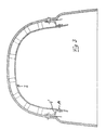
- Figure 1 shows an outer helmet cap 1, on the inside a basket 2 as part of the interior with the help is fastened by three fastening means 3. Two of the fastening middle 3 are in the temple area on both Sides of the helmet 1, the third fastener 3 centered on the back.
- the carrier basket consists of a central ring arrangement 4, which extends radially from a plurality of bands 5.
- the radially extended Bands 5 are interconnected by connecting bands 6 connected.
- the radial bands 5 open into the lower region a headband 7, which is approximately horizontal in the normal wearing state around the head of the helmet wearer.
- the radial bands 5, the connecting bands 6 and the head band 7 are provided with hollow knobs 8, by means of which the carrying basket 2 rests on the inside of the helmet cap 1.
- the pretension required for this is achieved by the suitable position of the fastening means 3 and is effective because the support basket 2, which is preferably formed from plastic, has its own dimensional stability.
- the knobs 8 are formed from the material of the support basket 2 and can be plastically deformed by higher pressures, so that impact or impact energy is absorbed by the knobs 8 due to the plastic deformation.
- FIG. 1 also shows that some of the knobs 8, for example not in the area of ear curvature of the helmet dome 1 fit the inside of the helmet. However, this applies to most of the knobs 8, so that the carrying basket in its entirety by the applied by the fasteners 3 Preload on the inside of the helmet cap 1 under pretension is applied.
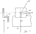
- FIG. 2 illustrates that the support basket 2 fastening parts 9th has, which together with a screwed into the helmet 1 Bolts 10 form the fastener 3.
- the illustrated embodiment is the fastening part 9 molded onto the support basket 2 in the form of an L-shaped angle and encompasses one protruding inward from the helmet cap 1 Part of the bolt 10 partially.
- a side limitation for the fastening part 9 results from one at the free End of the bolt 10 arranged bolt head 11, which is the fastening part 9 holds in place.
- the bolt 10 further carries a fastening device 12 for a chin strap 13, thus on the bolt 10 of the two lateral fastening means 3 is attached.
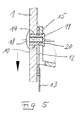
- FIG. 3 shows an embodiment variant of the arrangement according to FIG. 2, in which the fastening part 9 ′ on the carrier basket 2 is riveted by a rivet 14 and thus from another Material can exist as the support basket 2. This can if necessary, a higher dimensional stability of the fasteners 9 'can be achieved.
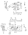
- Figure 4 shows a section according to Figure 2 ( Figure 4b) and a Top view of the fastener 9.
- the fastener is L-shaped and angled parallel to the inside the helmet 1 lying flat fork arrangement 15 with a receiving chamber 16 and an insertion slot 17, which as formed conically tapered to the receiving chamber 16 is.
- the diameter of the receiving chamber 16 corresponds to the outer diameter the bolt protruding from the helmet cap 1 10 by the constriction 17 in the direction of arrow A in Figure 4 can be pressed into the receiving chamber 16 and there in a Snap connection is held.
- Figure 5 illustrates that the bolt 10 from a pan head screw 18 and a sleeve 19 is composed.
- the attachment the bolt 10 is therefore done by screwing the Flat head screw 18 with the sleeve 19 shown in the Embodiment on the inside of the helmet 1 by the fastening part 12 snapped into a groove 20 the chin strap 13 is positioned.
- FIGs 6 and 7 show two specific embodiments of Fasteners 9 '' and 9 '' '.
- the one shown in Figure 6 Fastening piece 9 '' is in the embodiment shown in FIG 1 as a fastener 3 at the rear end of the helmet 1 used.
- the fastening part 9 '' points from that Carrier basket 2 starting from a height that the height of neighboring Nubs 8 corresponds (FIG. 6b), so that the helmet cap 1 facing surface of the fastening part 9 '' with the top the knob 8 with respect to the inside of the helmet cap 1 about escapes.
- Figure 6a shows that the fastener 9 ′′ the receiving chamber 16 and a constriction 17 forming it Has slot in which the bolt 10 after manufacture an excessive preload is insertable, the Preload of the basket 2 partially relaxed again.
- Figure 6c illustrates that in the fastening part 9 '' receiving chamber 16 and slot 17 part of a T-shaped in cross section Are groove 21, the T-shaped extension 22 of the groove 21st serves to guide the bolt head 11.
- Figure 7 shows a further embodiment of a fastening part 9 '' ', which are in relation to the receiving chamber 16, the Slot 17 and the T-shaped groove 21 not from the fastening part 9 '' differs.
- Figure 7b corresponds this embodiment of the angular formation of the fastening part 9 according to Figure 2, the height of the fastening part 9 '' 'is slightly lower than the height of an adjacent one Knob 8, because in addition to the fastening part 9 '' 'on the Bolt 10 still the fastening piece 12 for the chin strap is applied.
- the height difference between the fastener 9 '' 'and bolt 8 is therefore determined by the strength of the fastener 12 for the chin strap 13 somewhat filled.
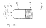
- a fastening part 12 for a chin strap 13 is shown in FIG. 8 shown.
- This has one of the receiving chamber 16 corresponding Receiving chamber 23 for the bolt 10.
- the reception chamber 23 is via a constriction 24 with an insertion opening 25 connected, the diameter of which is larger than the diameter of the bolt head 11, so that the bolt head 11 through the An insertion opening 25 can be inserted, whereupon the bolt via the constriction 24 into the receiving chamber 23 is snapped.
- the chin strap 13 is thus over the bolt 10 detentable.
- the direction of movement of the fastener 12 relative to the bolt for mounting the chin strap 13 is indicated by the arrow B in FIG.
Abstract
Description
Die Erfindung betrifft einen Schutzhelm, insbesondere militärischen Schutzhelm, mit einer stabilen Helmkalotte und einem aus mehreren miteinander verbundenen Bändern gebildeten Tragkorb, der an seine Bänder angeformte, zur Helmkalotte zeigende, plastisch verformbare Noppen aufweist und mit Befestigungsteilen so an mehreren Punkten mit der Helmkalotte verbunden ist, daß der Tragkorb über die Noppen mit einer Vorspannung an der Innenseite der Helmkalotte anliegt.The invention relates to a protective helmet, in particular military Hard hat, with a stable helmet cap and one out a plurality of straps connected to each other, the one molded onto its bands, pointing towards the helmet, plastic has deformable knobs and with fasteners is connected to the helmet at several points so that the basket over the knobs with a preload on the inside the helmet fits.
Ein derartiger Schutzhelm, wie er als militärischer Schutzhelm durch EP 0 423 379 B1 bekannt ist, verbindet die Funktion einer guten Stoßdämpfung durch die plastisch verformbaren Noppen des Tragkorbes der Innenausstattung mit einer guten Durchlüftbarkeit des Helms. Die auch beim Aufprall von Geschossen auf die für militärische Zwecke beschußfeste Helmkalotte auftretenden Schläge werden dadurch wirksam bedämpft, daß die Noppen fest an der Innenseite der Helmkalotte anliegen und somit unmittelbar beim Aufprall des Geschosses plastisch verformt werden. Die hierfür erforderliche Vorspannung des Tragekorbs gegenüber der Helmkalotte wird durch eine entsprechende Befestigung des Tragkorbes an der Helmkalotte sichergestellt. Der Tragkorb wird üblicherweise fest mit der Helmkalotte verschraubt, wodurch die nötige Vorspannung gewährleistet werden kann.Such a hard hat as he is a military hard hat is known from EP 0 423 379 B1, combines the function of a good shock absorption through the plastically deformable knobs the basket of the interior with good ventilation of the helmet. The same with the impact of projectiles those that are bulletproof for military purposes Blows are effectively dampened by the knobs fit snugly against the inside of the helmet and therefore immediately be plastically deformed when the projectile hits. The pretension of the carrier basket required for this the helmet is secured by an appropriate attachment the basket on the helmet cap ensured. The Carrying cage is usually screwed tightly to the helmet cap, which ensures the necessary preload can.
Durch andere Typen von Schutzhelmen, beispielsweise Motorradhelme, ist es bekannt, die Innenausstattung durch Druckknöpfe an der Helmkalotte zu befestigen und so insbesondere für Reinigungszwecke herausnehmbar auszubilden. Aufgrund der Vorspannung, mit der der Tragkorb des gattungsgemäßen Schutzhelms zur Erzielung einer guten Stoßdämpfung an der Helmkalotte anliegen muß, ist eine Druckknopfbefestigung zur Gewährleistung der Herausnehmbarkeit des Tragkorbes nicht mit der erforderlichen Befestigungssicherheit realisierbar.Other types of protective helmets, such as motorcycle helmets, it is known the interior by push buttons to attach to the helmet and so especially for cleaning purposes to be removable. Because of the preload, with the the basket of the generic safety helmet to achieve good shock absorption on the helmet cap is a push button attachment to ensure the removability of the basket not with the required fastening security can be realized.
Durch US-A-3,026,523 ist ein Arbeitsschutzhelm bekannt, dessen Tragkorb mit einem Abstand zur Helmkalotte angeordnet und an der Helmkalotte mit Hilfe eines schlüssellochähnlichen Schlitzes befestigt wird, wobei ein Befestigungsbolzen in dem schlüssellochähnlichen Schlitz im eingerasteten Zustand am unteren geschlossenen Ende des schlüssellochähnlichen Schlitzes liegt. Von oben nach unten gerichtete Stöße auf die Helmkalotte drücken somit den Bolzen der Helmkalotte gegen den unteren Rand des schlüssellochähnlichen Schlitzes, an dem der Bolzen im eingerasteten Zustand bereits anliegt. Dadurch werden die unteren Enden des Tragkorbes mit der Helmkalotte unter der Stoßeinwirkung nach unten gezogen und eine stoßdämpfende Wirkung durch eine Längung der Bänder des Tragkorbes in den Abstandsraum zwischen Tragkorb und Helmkalotte hinein erzielt. Ein Anliegen des Tragkorbes an der Helmkalotte ist nicht vorgesehen und würde die stoßdämpfende Wirkung des Arbeitsschutzhelmes eliminieren.A work safety helmet is known from US-A-3,026,523 Carrying basket arranged at a distance from the helmet cap and on the helmet with the help of a keyhole-like Slot is attached, using a mounting bolt in the keyhole-like slot in the locked Condition at the lower closed end of the keyhole-like Slot lies. Shocks from top to bottom press the bolt of the helmet cap on the helmet cap against the bottom of the keyhole-like slot, on which the bolt is already in contact. As a result, the lower ends of the carrier basket with the Helmet cap pulled down under the impact and a shock-absorbing effect by elongating the bands of the Carrying basket in the space between the carrying basket and helmet cap achieved into it. A concern of the carrier on the Helmet is not provided and would be the shock absorbing Eliminate the effect of the safety helmet.
Zur Reinigung des Tragkorbes ist es daher bei den bekannten Schutzhelmen der gattungsgemäßen Art erforderlich, die üblicherweise an drei Punkten erfolgte Verschraubung der Innenausstattung mit der Helmkalotte zu lösen, sodass ein gewisser Montageaufwand benötigt wird.To clean the basket it is therefore in the known Protective helmets of the generic type are required, which are usually The interior fittings were screwed at three points to solve with the helmet, so that a certain Assembly effort is required.
Ausgehend von der Problemstellung, den Montageaufwand für die Entfernung der mit dem Tragkorb gebildeten Innenausstattung zu reduzieren ist erfindungsgemäß ein Schutzhelm der eingangs erwähnten Art dadurch gekennzeichnet, dass die Verbindung von Befestigungsteilen und Helmkalotte durch einen Bolzen und eine den Bolzen übergreifende Gabelanordnung gebildet ist, deren offene Seite so ausgerichtet ist, dass die Einführung des Bolzens aus einer erhohten Vorspannung des Tragkorbes gegen die Helmkalotte unter Reduzierung der Vorspannung erfolgt und dass der Bolzen durch Anliegen an der geschlossenen Seite der Gabelanordnung die für den Gebrauch gewünschte Vorspannung sichert.Based on the problem, the assembly effort for the removal of the interior formed with the carrier basket to reduce a protective helmet according to the invention type mentioned characterized in that the connection of fasteners and helmet cap by one Bolts and a fork arrangement overlapping the bolts are formed whose open side is oriented so that the Introduction of the bolt from an increased preload of the Carrier basket against the helmet cap while reducing the preload takes place and that the bolt is in contact with the closed side of the fork assembly for use secures the desired preload.
Erfindungsgemäß kann der Tragkorb ohne Montageaufwand von der Helmkalotte entfernt werden, wenn die Verbindung durch eine Bolzen-Gabel-Anordnung gebildet ist und die Montage so erfolgt, da der Tragkorb in einen Zustand einer erhöhten Vorspannung gepresst wird und sich teilweise entspannend an der Bolzen-Gabel-Anordnung abstützt, sodass die für den Gebrauch verbleibende Vorspannung bereits zur Sicherung der Verbindung beiträgt, weil ein zufälliges Lösen der Verbindung wegen der dafür erforderlichen Erhöhung der Vorspannung in der Praxis ausgeschlossen ist. According to the invention, the carrying basket can be assembled without the calotte can be removed when the connection is through a bolt-fork arrangement is formed and the assembly so takes place because the carrying basket is in a state of an elevated Preload is pressed and partially relaxing the bolt-fork assembly supports so that it is ready for use remaining preload already to secure the Connection contributes because accidental disconnection because of the necessary increase in preload is excluded in practice.
Die Sicherung der Bolzen-Gabel-Verbindung kann noch dadurch verbessert werden, daß die Gabel-Anordnung eine die offene Seite bildende elastisch verformbare Verengung als Einführweg für den Bolzen und an der geschlossenen Seite eine der Außenabmessung des Bolzens entsprechende Aufnahmekammer aufweist, in die der Bolzen schnappend einführbar ist.This can still secure the bolt-fork connection be improved that the fork arrangement an the open Elastic deformable constriction on the side as an insertion path for the bolt and one of the outer dimensions on the closed side of the bolt has a corresponding receiving chamber, into which the bolt can be snapped in.
Mit der Bolzen-Gabel-Verbindung kann zusätzlich eine seitliche Sicherung herbeigeführt werden, wenn der Bolzen einen Bolzenkopf aufweist, dessen Durchmesser größer als der der Aufnahmekammer ist. Dabei kann der Bolzenkopf auf der Rückseite der Aufnahmekammer frei anliegen oder zur Erhöhung der Stabilität der Verbindung in einer Führungsnut geführt sein, die für den Bolzenkopf im Querschnitt T-förmig ausgebildet ist.The bolt-fork connection can also be used for a side Fuse can be brought about when the bolt hits a bolt head has a diameter larger than that of the receiving chamber is. The bolt head on the back of the Hold the receiving chamber freely or to increase stability the connection be guided in a guide groove for the Bolt head is T-shaped in cross section.
Im allgemeinen wird es zweckmäßig sein, daß der Bolzen am Helm und die Gabel-Anordnung am Befestigungsstreifen angebracht sind. Der Bolzen läßt sich als Schraubbolzen in einfacher Weise am Helm befestigen, wobei durch Maßnahmen, wie sie in EP 0 662 286 A1 offenbart sind, auch eine unverminderte Beschußfestigkeit im Bereich des für die Verschraubung erforderlichen Durchbruches der Helmkalotte erhalten bleiben kann.In general, it will be appropriate that the bolt on the helmet and attached the fork assembly to the mounting strip are. The bolt can be used as a bolt in a simple manner attach to the helmet, taking measures as described in EP 0 662 286 A1 are also disclosed, an undiminished bullet resistance in the area of the necessary for the screw connection Breakthrough of the helmet can be preserved.
In einer bevorzugten Ausführungsform befinden sich die Befestigungspunkte im unteren Bereich des Tragkorbes, wobei dann die offene Seite der Gabel-Anordnung zur Öffnungsseite der Helmkalotte zeigt, wenn die Gabel-Anordnung am Befestigungsteil angebracht ist.In a preferred embodiment, the attachment points are located in the lower area of the carrier, where then the open side of the fork arrangement to the opening side of the helmet cap shows when the fork assembly is attached to the fastener is.
Der erfindungsgemäß verwendete Bolzen kann zweckmäßigerweise gleichzeit zur Befestigung eines Kinnriemens ausgenutzt werden, wobei auch der Kinnriemen abnehmbar befestigt sein kann. The bolt used according to the invention can expediently can be used to attach a chin strap at the same time, the chin strap can also be removably attached.
Die Erfindung soll im folgenden anhand von in der Zeichnung dargestellten Ausführungsbeispielen näher erläutert werden. Es zeigen:
Figur 1- eine Ansicht durch die Öffnungsseite eines erfindungsgemäßen Helmes auf seine Innenseite
Figur 2- einen Vertikalschnitt durch den Helm gemäß
Figur 1 im Bereich der vorderen Befestigungspunkte Figur 3- eine Darstellung gemäß
Figur 2 für eine Variante Figur 4- eine vergrößerte Darstellung eines Befestigungsteils für den Tragkorb
Figur 5- eine Schnittdarstellung einer Befestigung des Befestigungsteils an einem in die Helmkalotte eingeschraubten Bolzen
Figur 6- Ansichten eines ersten Asuführungsbeispiels eines Befestigungsteils,
das an der Helmrückseite gemäß
Figur 1 verwendbar ist Figur 7- Ansichten eines Befestigungsteils, das an seitlichen Befestigungspunkten verwendbar ist
Figur 8- eine Ansicht eines Befestigungsteils für einen Kinn-riemen.
- Figure 1
- a view through the opening side of a helmet according to the invention on its inside
- Figure 2
- a vertical section through the helmet according to Figure 1 in the area of the front attachment points
- Figure 3
- a representation of Figure 2 for a variant
- Figure 4
- an enlarged view of a fastening part for the carrier basket
- Figure 5
- a sectional view of a fastening of the fastening part on a bolt screwed into the helmet cap
- Figure 6
- Views of a first example of a fastening part which can be used on the rear of the helmet according to FIG. 1
- Figure 7
- Views of a fastening part that can be used at lateral fastening points
- Figure 8
- a view of a fastener for a chin strap.
Figur 1 läßt eine äußere Helmkalotte 1 erkennen, an deren Innenseite
ein Tragkorb 2 als Teil der Innenausstattung mit Hilfe
von drei Befestigungsmitteln 3 befestigt ist. Zwei der Befestigungs-
mittel 3 befinden sich im Schläfenbereich auf beiden
Seiten der Helmkalotte 1, das dritte Befestigungsmittel 3
mittig auf der Rückseite.Figure 1 shows an
Der Tragkorb besteht aus einer zentralen Ringanordnung 4, von
der aus sich radial mehrere Bänder 5 erstrecken. Die radial erstreckten
Bänder 5 sind durch Verbindungsbänder 6 miteinander
verbunden. Im unteren Bereich münden die radialen Bänder 5 in
ein Kopfband 7 ein, das im normalen Tragezustand etwa horizontal
um den Kopf des Helmträgers umläuft.The carrier basket consists of a
Die radialen Bänder 5, die Verbindungsbänder 6 und das Kopfband
7 sind mit hohl ausgebildeten Noppen 8 versehen, über die
der Tragkorb 2 an der Innenseite der Helmkalotte 1 anliegt.
Die hierfür benötigte Vorspannung wird durch die geeignete
Lage der Befestigungsmittel 3 erreicht und wird wirksam, weil
der Tragkorb 2, der vorzugsweise aus Kunststoff gebildet ist,
eine eigene Formstabilität aufweist. Die Noppen 8 sind aus dem
Material des Tragkorbes 2 gebildet und plastisch durch höhere
Drücke verformbar, so daß Stoß- oder Schlagenergie durch die
plastische Verformung von den Noppen 8 aufgenommen wird.The
The pretension required for this is achieved by the suitable position of the fastening means 3 and is effective because the
Figur 1 läßt auch erkennen, daß einige der Noppen 8, beispielsweise
im Bereich von Ohrwölbungen der Helmkalotte 1 nicht an
der Innenseite der Helmkalotte anliegen. Dies gilt jedoch für
die meisten der Noppen 8, so daß der Tragkorb in seiner Gesamtheit
durch die von den Befestigungsmitteln 3 aufgebrachte
Vorspannung an der Innenseite der Helmkalotte 1 unter Vorspannung
anliegt.Figure 1 also shows that some of the
Figur 2 verdeutlicht, daß der Tragkorb 2 Befestigungsteile 9
aufweist, die zusammen mit einem in die Helmkalotte 1 eingeschraubten
Bolzen 10 das Befestigungsmittel 3 bilden. In dem
dargestellten Ausführungsbeispiel ist das Befestigungsteil 9
in Form eines L-förmigen Winkels an den Tragkorb 2 angeformt
und umgreift einen von der Helmkalotte 1 nach innen vorstehenden
Teil des Bolzens 10 teilweise. Eine seitliche Begrenzung
für das Befestigungsteil 9 ergibt sich durch einen am freien
Ende des Bolzens 10 angeordneten Bolzenkopf 11, der das Befestigungsteil
9 in Position hält.Figure 2 illustrates that the
In Figur 2 ist ferner angedeutet, daß der Bolzen 10 ferner
eine Befestigungseinrichtung 12 für einen Kinnriemen 13 trägt,
der somit an den Bolzen 10 der beiden seitlichen Befestigungsmittel
3 befestigt ist.In Figure 2 it is also indicated that the
Figur 3 zeigt eine Ausführungsvariante der Anordnung gemäß
Figur 2, bei der das Befestigungsteil 9' an den Tragkorb 2
durch einen Niet 14 angenietet ist und somit aus einem anderen
Material als der Tragkorb 2 bestehen kann. Hierdurch kann,
falls erforderlich, eine höhere Formstabilität der Befestigungsteile
9' erreicht werden.FIG. 3 shows an embodiment variant of the arrangement according to
FIG. 2, in which the
Figur 4 zeigt einen Schnitt gemäß Figur 2 (Figur 4b) und eine
Draufsicht des Befestigungsteils 9. Das Befestigungsteil ist
L-förmig abgekröpft und bildet eine parallel zur Innenseite
der Helmkalotte 1 liegende flächige Gabel-Anordnung 15 mit
einer Aufnahmekammer 16 und einem Einführschlitz 17, der als
zur Aufnahmekammer 16 konisch verjüngte Verengung ausgebildet
ist. Der Durchmesser der Aufnahmekammer 16 entspricht dem Außendurchmesser
des von der Helmkalotte 1 vorstehenden Bolzens
10, der durch die Verengung 17 in Richtung des Pfeiles A in
Figur 4 in die Aufnahmekammer 16 drückbar ist und dort in einer
Schnappverbindung gehalten wird.Figure 4 shows a section according to Figure 2 (Figure 4b) and a
Top view of the
Die Ausführung der Einführungsbewegung des Bolzens 10 in die
Aufnahmekammer 16 der Gabel-Anordnung 15 setzt voraus, daß -
wie den Figuren 2 und 3 zu entnehmen ist - der Tragkorb 2
stärker als in der Gebrauchsstellung gemäß Figur 2 oder 3 in
Richtung Helmoberseite gedrückt wird, wobei sich der Tragkorb
2 beim Einführen durch die Verengung 17 in die Aufnahmekammer
16 teilweise wieder entspannt. Das der Verengung 17 gegenüberliegende
geschlossene Ende der Aufnahmekammer 16 bewirkt zusammen
mit dem Bolzen 10, daß der Tragkorb 2 in der in Gebrauchsstellung
gewünschten Vorspannung gegenüber der Innenseite
der Helmkalotte 1 gehalten wird.The execution of the insertion movement of the
Figur 5 verdeutlicht, daß der Bolzen 10 aus einer Flachkopfschraube
18 und einer Hülse 19 zusammengesetzt ist. Die Befestigung
des Bolzens 10 geschieht daher durch Verschraubung der
Flachkopfschraube 18 mit der Hülse 19, die in dem dargestellten
Ausführungsbeispiel auf der Innenseite der Helmkalotte 1
durch das in eine Nut 20 eingeschnappte Befestigungsteil 12
des Kinn-riemens 13 positioniert wird. Zwischen Befestigungsteil
12 und Bolzenkopf 11, der durch den Boden der Hülse 19
gebildet ist, befindet sich der Raum für die Aufnahme der Gabel-Anordnung
15.Figure 5 illustrates that the
Die Figuren 6 und 7 zeigen zwei konkrete Ausführungsformen von
Befestigungsstücken 9'' und 9'''. Das in Figur 6 dargestellte
Befestigungsstück 9'' wird in dem Ausführungsbeispiel gemäß Figur
1 als Befestigungsmittel 3 am hinteren Ende der Helmkalotte
1 verwendet. Das Befestigungsteil 9'' weist von dem
Tragkorb 2 ausgehend eine Höhe auf, die der Höhe benachbarter
Noppen 8 entspricht (Fig. 6b), so daß die der Helmkalotte 1
zugewandte Oberfläche des Befestigungsteils 9'' mit der Oberseite
der Noppen 8 bezüglich der Innenseite der Helmkalotte 1
etwa fluchtet. Figur 6a läßt erkennen, daß das Befestigungsteil
9'' die Aufnahmekammer 16 und einen die Verengung 17 bildenden
Schlitz aufweist, in die der Bolzen 10 nach Herstellung
einer übergroßen Vorspannung einführbar ist, wobei sich die
Vorspannung des Tragkorbs 2 teilweise wieder entspannt.Figures 6 and 7 show two specific embodiments of
Fasteners 9 '' and 9 '' '. The one shown in Figure 6
Fastening piece 9 '' is in the embodiment shown in FIG
1 as a
Figur 6c verdeutlicht, daß in dem Befestigungsteil 9'' Aufnahmekammer
16 und Schlitz 17 Teil einer im Querschnitt T-förmigen
Nut 21 sind, wobei die T-förmige Erweiterung 22 der Nut 21
der Führung des Bolzenkopfs 11 dient.Figure 6c illustrates that in the fastening part 9 '' receiving
Figur 7 zeigt eine weitere Ausführungsform eines Befestigungsteils
9''', die sich bezüglich der Aufnahmekammer 16, des
Schlitzes 17 und der T-förmigen Nut 21 nicht von dem Befestigungsteil
9'' unterscheidet. Wie Figur 7b zeigt, entspricht
diese Ausführungsform der winkeligen Ausbildung des Befestigungsteils
9 gemäß Figur 2, wobei die Höhe des Befestigungsteils
9''' etwas niedriger ist als die Höhe einer benachbarten
Noppe 8, weil zusätzlich zu dem Befestigungsteil 9''' auf den
Bolzen 10 noch das Befestigungsstück 12 für den Kinnriemen
aufgebracht wird. Die Höhendifferenz zwischen Befestigungsteil
9''' und Bolzen 8 wird daher durch die Stärke des Befestigungsteils
12 für den Kinn-riemen 13 etwas ausgefüllt. Figure 7 shows a further embodiment of a fastening part
9 '' ', which are in relation to the receiving
Ein Befestigungsteil 12 für einen Kinnriemen 13 ist in Figur 8
dargestellt. Dieses weist eine der Aufnahmekammer 16 entsprechende
Aufnahmekammer 23 für den Bolzen 10 auf. Die Aufnahmekammer
23 ist über eine Verengung 24 mit einer Einführungsöffnung
25 verbunden, deren Durchmesser größer als der Durchmesser
des Bolzenkopfs 11 ist, so daß der Bolzenkopf 11 durch die
Ein-führungsöffnung 25 hindurch gesteckt werden kann, woraufhin
der Bolzen über die Verengung 24 in die Aufnahmekammer 23
einschnappbar ist. Der Kinnriemen 13 ist somit über den Bolzen
10 rastend hängbar. Die Bewegungsrichtung des Befestigungsteils
12 relativ zum Bolzen für die Montage des Kinnriemens 13
ist in Figur 8 durch den Pfeil B angedeutet.A
Aus den dargestellten Ausführungsbeispielen ist erkennbar, daß
durch die Ausbildung der Befestigungseinrichtungen 3 mit einem
Bolzen 10 und einer Gabel-Anordnung 15 die Vorspannung des
Trag-korbes 2 gegenüber der Helmkalotte 1 für die Befestigung
nicht nur nicht hinderlich ist, sondern für die Stabilität der
Befestigung ausgenutzt wird, wobei zur Montage der Befestigungsvorrichtung
3 der Tragkorb 2 in eine übergroße Vorspannung
gedrückt werden muß, aus der er sich teilweise entspannend
in die Gabel-Anordnung 15 hineindrückt und dort unter
Vorspannung an dem dem Schlitz 17 gegenüberliegenden geschlossenen
Ende der Aufnahmekammer 16 anliegt.From the illustrated embodiments it can be seen that
through the formation of the
Claims (8)
- A protective helmet, in particular a military protective helmet, having a stable helmet dome (1) and a supporting basket (2) which is formed from a plurality of mutually connected bands (5, 6, 7), has plastically deformable lugs (8) which are integrally formed on its bands (5, 6, 7) and point towards the helmet dome (1), and is connected to the helmet dome (1) at a plurality of points by means of fastening parts (9, 9', 9'', 9'''), such that, by way of the lugs (8), the supporting basket (2) abuts against the inside of the helmet dome (1) under pre-tension, characterised in that the connection between the fastening parts (9, 9', 9'', 9''') and the helmet dome (1) is formed by a bolt (10) and a fork-type arrangement (15), which reaches over the bolt (10) and whereof the open side (17) is aligned such that, as a result of an increased pre-tension of the supporting basket (2) towards the helmet dome (1), the bolt (10) is guided in and the pre-tension decreases, and in that the bolt (10) ensures the desired pre-tension for use by abutting against the closed side of the fork-type arrangement (15).
- A protective helmet according to Claim 1, characterised in that the fork-type arrangement (15) has a resiliently deformable narrowing (17) forming the open side as the path for guiding in the bolt (10), and a receiving chamber (16) at the closed side, which corresponds to the external dimensions of the bolt (10) and into which the bolt (10) may be guided in snap-in manner.
- A protective helmet according to Claim 2, characterised in that the bolt (10) has a bolt head (11) whereof the diameter is greater than that of the receiving chamber (16).
- A protective helmet according to Claim 3, characterised in that the fork-type arrangement (15) has a T-shaped guide groove (21) which at the same time serves to guide the bolt head (11).
- A protective helmet according to one of Claims 1 to 4, characterised in that the bolt (10) is mounted on the helmet dome (1) and the fork-type arrangement (15) is mounted on the fastening part (9, 9', 9'', 9''').
- A protective helmet according to Claim 5, characterised in that the fastening points are located in the lower region of the supporting basket (2), and in that the open side (17) of the fork-type arrangement (15) points towards the opening side of the helmet dome (1).
- A protective helmet according to one of Claims 1 to 6, characterised in that the surface of the fastening parts (9, 9', 9'', 9''') which points towards the helmet dome (1) is approximately flush with lugs (8) adjacent to the upper side.
- A protective helmet according to one of Claims 1 to 7, characterised in that a chin strap (13) is additionally fastened to the bolt (10).
Applications Claiming Priority (3)
| Application Number | Priority Date | Filing Date | Title |
|---|---|---|---|
| DE19621004 | 1996-05-24 | ||
| DE19621004A DE19621004C2 (en) | 1996-05-24 | 1996-05-24 | Safety helmet, in particular military safety helmet |
| PCT/DE1997/001060 WO1997045032A1 (en) | 1996-05-24 | 1997-05-23 | Safety helmet, in particular military safety helmet |
Publications (2)
| Publication Number | Publication Date |
|---|---|
| EP0840558A1 EP0840558A1 (en) | 1998-05-13 |
| EP0840558B1 true EP0840558B1 (en) | 2002-01-02 |
Family
ID=7795253
Family Applications (1)
| Application Number | Title | Priority Date | Filing Date |
|---|---|---|---|
| EP97926965A Expired - Lifetime EP0840558B1 (en) | 1996-05-24 | 1997-05-23 | Safety helmet, in particular military safety helmet |
Country Status (8)
| Country | Link |
|---|---|
| EP (1) | EP0840558B1 (en) |
| AT (1) | ATE211364T1 (en) |
| AU (1) | AU3164097A (en) |
| DE (3) | DE19621004C2 (en) |
| DK (1) | DK0840558T3 (en) |
| ES (1) | ES2169396T3 (en) |
| PT (1) | PT840558E (en) |
| WO (1) | WO1997045032A1 (en) |
Families Citing this family (5)
| Publication number | Priority date | Publication date | Assignee | Title |
|---|---|---|---|---|
| NO323512B1 (en) | 2004-04-07 | 2007-06-04 | Crescendo As | Stop mold for making a helmet lining. |
| DE102009038764B4 (en) * | 2009-08-27 | 2016-02-04 | Schuberth Gmbh | Hard hat with a hard inner dome and a shock absorbing interior |
| DE102010027015A1 (en) * | 2010-07-13 | 2012-01-19 | Anton Pfanner | Face shield for attachment to a protective helmet, in particular for forestry workers |
| DE102010027014A1 (en) * | 2010-07-13 | 2012-01-19 | Anton Pfanner | Interior equipment for a safety helmet, especially for forestry workers |
| DE102010026998A1 (en) * | 2010-07-13 | 2012-01-19 | Anton Pfanner | Clamping unit for a carrying strap of a protective helmet, in particular for forestry workers |
Family Cites Families (9)
| Publication number | Priority date | Publication date | Assignee | Title |
|---|---|---|---|---|
| US2585937A (en) * | 1949-08-01 | 1952-02-19 | Willson Products Inc | Safety hat |
| US2763863A (en) * | 1954-06-30 | 1956-09-25 | Fibre Metal Prod Co | Head protector cradle attachment |
| GB898954A (en) * | 1959-06-29 | 1962-06-14 | United Carr Fastener Corp | Improvements in and relating to socket devices for engagement with a cooperating stud |
| US3026523A (en) * | 1959-12-08 | 1962-03-27 | Fibre Metal Products Company | Suspension harness for safety hats |
| US3241154A (en) * | 1963-12-03 | 1966-03-22 | Leonard P Frieder | Safety helmets |
| US3451066A (en) * | 1967-10-19 | 1969-06-24 | United Carr Inc | Detachable helmet liner suspension harness |
| US3797039A (en) * | 1972-04-10 | 1974-03-19 | Penberthy Harvey Larry | Safety helmet |
| EP0423379B1 (en) * | 1989-10-14 | 1993-07-28 | Schuberth-Werk GmbH & Co. KG | Military protective helmet |
| DE9400161U1 (en) * | 1994-01-07 | 1994-03-24 | Schuberth Werk Kg | Bulletproof helmet |
-
1996
- 1996-05-24 DE DE19621004A patent/DE19621004C2/en not_active Expired - Fee Related
-
1997
- 1997-05-23 EP EP97926965A patent/EP0840558B1/en not_active Expired - Lifetime
- 1997-05-23 WO PCT/DE1997/001060 patent/WO1997045032A1/en active IP Right Grant
- 1997-05-23 DE DE59706090T patent/DE59706090D1/en not_active Expired - Fee Related
- 1997-05-23 PT PT97926965T patent/PT840558E/en unknown
- 1997-05-23 AU AU31640/97A patent/AU3164097A/en not_active Abandoned
- 1997-05-23 AT AT97926965T patent/ATE211364T1/en not_active IP Right Cessation
- 1997-05-23 DK DK97926965T patent/DK0840558T3/en active
- 1997-05-23 DE DE29780370U patent/DE29780370U1/en not_active Expired - Lifetime
- 1997-05-23 ES ES97926965T patent/ES2169396T3/en not_active Expired - Lifetime
Also Published As
| Publication number | Publication date |
|---|---|
| DE29780370U1 (en) | 1998-08-20 |
| WO1997045032A1 (en) | 1997-12-04 |
| DE19621004A1 (en) | 1997-11-27 |
| ES2169396T3 (en) | 2002-07-01 |
| PT840558E (en) | 2002-06-28 |
| DE19621004C2 (en) | 2000-02-24 |
| EP0840558A1 (en) | 1998-05-13 |
| DE59706090D1 (en) | 2002-02-28 |
| AU3164097A (en) | 1998-01-05 |
| DK0840558T3 (en) | 2002-03-18 |
| ATE211364T1 (en) | 2002-01-15 |
Similar Documents
| Publication | Publication Date | Title |
|---|---|---|
| DE102009038764B4 (en) | Hard hat with a hard inner dome and a shock absorbing interior | |
| DE60100845T2 (en) | PROTECTIVE HELMET WITH DEVICE FOR ADJUSTING THE HEAD | |
| DE102010050678B3 (en) | Protective arrangement for the body of a living being, in particular protective helmet | |
| EP0301368B1 (en) | Cervical support | |
| DE6608232U (en) | EAR PROTECTORS WITH AT LEAST ONE NOISE-CUTTING EAR CUP. | |
| DE2921267A1 (en) | HEADGEAR FOR AND IN CONNECTION WITH VARIOUS ADDITIONAL PARTS | |
| DE7725175U1 (en) | Hard hat | |
| WO2016019406A2 (en) | Protective helmet | |
| DE102006058782A1 (en) | Head protection device has hard shell made so as to be adaptable to shape and/or size of head of user in region of back of head | |
| WO1999020133A1 (en) | Safety helmet with a dimensionally stable helmet shell | |
| EP0423379B1 (en) | Military protective helmet | |
| DE102017108038A1 (en) | Adjustable damping insert | |
| EP0840558B1 (en) | Safety helmet, in particular military safety helmet | |
| EP3054801B1 (en) | Protective helmet | |
| DE19721146C2 (en) | Safety helmet, in particular military safety helmet | |
| DE4336665C2 (en) | Hard hat | |
| DE2318041A1 (en) | ENERGY-EATING CONNECTOR | |
| CH688979A5 (en) | Helmet. | |
| EP0662286B1 (en) | Ballistic helmet | |
| EP3827683B1 (en) | Head protection system | |
| EP0056428B1 (en) | Body of elastic material for mounting slats to the sides of a bed frame | |
| DE8107236U1 (en) | "Interior fittings for protective helmets" | |
| DE102008020947B4 (en) | Hard hat with helmet belt | |
| DE102009038763B4 (en) | Hard hat with a tight helmet dome | |
| EP2165616A2 (en) | Protective helmet |
Legal Events
| Date | Code | Title | Description |
|---|---|---|---|
| PUAI | Public reference made under article 153(3) epc to a published international application that has entered the european phase |
Free format text: ORIGINAL CODE: 0009012 |
|
| 17P | Request for examination filed |
Effective date: 19980107 |
|
| AK | Designated contracting states |
Kind code of ref document: A1 Designated state(s): AT BE CH DE DK ES FR GB GR LI NL PT SE |
|
| 17Q | First examination report despatched |
Effective date: 20000428 |
|
| GRAG | Despatch of communication of intention to grant |
Free format text: ORIGINAL CODE: EPIDOS AGRA |
|
| GRAG | Despatch of communication of intention to grant |
Free format text: ORIGINAL CODE: EPIDOS AGRA |
|
| GRAH | Despatch of communication of intention to grant a patent |
Free format text: ORIGINAL CODE: EPIDOS IGRA |
|
| GRAH | Despatch of communication of intention to grant a patent |
Free format text: ORIGINAL CODE: EPIDOS IGRA |
|
| GRAA | (expected) grant |
Free format text: ORIGINAL CODE: 0009210 |
|
| REG | Reference to a national code |
Ref country code: GB Ref legal event code: IF02 |
|
| AK | Designated contracting states |
Kind code of ref document: B1 Designated state(s): AT BE CH DE DK ES FR GB GR LI NL PT SE |
|
| REF | Corresponds to: |
Ref document number: 211364 Country of ref document: AT Date of ref document: 20020115 Kind code of ref document: T |
|
| REG | Reference to a national code |
Ref country code: CH Ref legal event code: NV Representative=s name: BRAUN & PARTNER PATENT-, MARKEN-, RECHTSANWAELTE Ref country code: CH Ref legal event code: EP |
|
| REF | Corresponds to: |
Ref document number: 59706090 Country of ref document: DE Date of ref document: 20020228 |
|
| REG | Reference to a national code |
Ref country code: DK Ref legal event code: T3 |
|
| GBT | Gb: translation of ep patent filed (gb section 77(6)(a)/1977) |
Effective date: 20020327 |
|
| PGFP | Annual fee paid to national office [announced via postgrant information from national office to epo] |
Ref country code: GR Payment date: 20020510 Year of fee payment: 6 |
|
| PGFP | Annual fee paid to national office [announced via postgrant information from national office to epo] |
Ref country code: DK Payment date: 20020527 Year of fee payment: 6 |
|
| PGFP | Annual fee paid to national office [announced via postgrant information from national office to epo] |
Ref country code: NL Payment date: 20020531 Year of fee payment: 6 |
|
| ET | Fr: translation filed | ||
| REG | Reference to a national code |
Ref country code: PT Ref legal event code: SC4A Free format text: AVAILABILITY OF NATIONAL TRANSLATION Effective date: 20020327 |
|
| REG | Reference to a national code |
Ref country code: ES Ref legal event code: FG2A Ref document number: 2169396 Country of ref document: ES Kind code of ref document: T3 |
|
| REG | Reference to a national code |
Ref country code: GR Ref legal event code: EP Ref document number: 20020401087 Country of ref document: GR |
|
| PLBE | No opposition filed within time limit |
Free format text: ORIGINAL CODE: 0009261 |
|
| STAA | Information on the status of an ep patent application or granted ep patent |
Free format text: STATUS: NO OPPOSITION FILED WITHIN TIME LIMIT |
|
| 26N | No opposition filed | ||
| PGFP | Annual fee paid to national office [announced via postgrant information from national office to epo] |
Ref country code: GB Payment date: 20030430 Year of fee payment: 7 Ref country code: ES Payment date: 20030430 Year of fee payment: 7 Ref country code: PT Payment date: 20030430 Year of fee payment: 7 |
|
| PGFP | Annual fee paid to national office [announced via postgrant information from national office to epo] |
Ref country code: SE Payment date: 20030507 Year of fee payment: 7 |
|
| PGFP | Annual fee paid to national office [announced via postgrant information from national office to epo] |
Ref country code: DE Payment date: 20030514 Year of fee payment: 7 Ref country code: BE Payment date: 20030514 Year of fee payment: 7 |
|
| PGFP | Annual fee paid to national office [announced via postgrant information from national office to epo] |
Ref country code: AT Payment date: 20030520 Year of fee payment: 7 |
|
| PGFP | Annual fee paid to national office [announced via postgrant information from national office to epo] |
Ref country code: FR Payment date: 20030528 Year of fee payment: 7 Ref country code: CH Payment date: 20030528 Year of fee payment: 7 |
|
| PG25 | Lapsed in a contracting state [announced via postgrant information from national office to epo] |
Ref country code: NL Free format text: LAPSE BECAUSE OF NON-PAYMENT OF DUE FEES Effective date: 20031201 Ref country code: DK Free format text: LAPSE BECAUSE OF NON-PAYMENT OF DUE FEES Effective date: 20031201 |
|
| PG25 | Lapsed in a contracting state [announced via postgrant information from national office to epo] |
Ref country code: GR Free format text: LAPSE BECAUSE OF NON-PAYMENT OF DUE FEES Effective date: 20031203 |
|
| REG | Reference to a national code |
Ref country code: DK Ref legal event code: EBP |
|
| NLV4 | Nl: lapsed or anulled due to non-payment of the annual fee |
Effective date: 20031201 |
|
| PG25 | Lapsed in a contracting state [announced via postgrant information from national office to epo] |
Ref country code: GB Free format text: LAPSE BECAUSE OF NON-PAYMENT OF DUE FEES Effective date: 20040523 Ref country code: AT Free format text: LAPSE BECAUSE OF NON-PAYMENT OF DUE FEES Effective date: 20040523 |
|
| PG25 | Lapsed in a contracting state [announced via postgrant information from national office to epo] |
Ref country code: SE Free format text: LAPSE BECAUSE OF NON-PAYMENT OF DUE FEES Effective date: 20040524 Ref country code: ES Free format text: LAPSE BECAUSE OF NON-PAYMENT OF DUE FEES Effective date: 20040524 |
|
| PG25 | Lapsed in a contracting state [announced via postgrant information from national office to epo] |
Ref country code: LI Free format text: LAPSE BECAUSE OF NON-PAYMENT OF DUE FEES Effective date: 20040531 Ref country code: CH Free format text: LAPSE BECAUSE OF NON-PAYMENT OF DUE FEES Effective date: 20040531 Ref country code: BE Free format text: LAPSE BECAUSE OF NON-PAYMENT OF DUE FEES Effective date: 20040531 |
|
| PG25 | Lapsed in a contracting state [announced via postgrant information from national office to epo] |
Ref country code: PT Free format text: LAPSE BECAUSE OF NON-PAYMENT OF DUE FEES Effective date: 20041123 |
|
| BERE | Be: lapsed |
Owner name: *SCHUBERTH-WERK G.M.B.H. & CO. K.G. Effective date: 20040531 |
|
| PG25 | Lapsed in a contracting state [announced via postgrant information from national office to epo] |
Ref country code: DE Free format text: LAPSE BECAUSE OF NON-PAYMENT OF DUE FEES Effective date: 20041201 |
|
| EUG | Se: european patent has lapsed | ||
| GBPC | Gb: european patent ceased through non-payment of renewal fee |
Effective date: 20040523 |
|
| REG | Reference to a national code |
Ref country code: CH Ref legal event code: PL |
|
| PG25 | Lapsed in a contracting state [announced via postgrant information from national office to epo] |
Ref country code: FR Free format text: LAPSE BECAUSE OF NON-PAYMENT OF DUE FEES Effective date: 20050131 |
|
| REG | Reference to a national code |
Ref country code: PT Ref legal event code: MM4A Effective date: 20041123 |
|
| REG | Reference to a national code |
Ref country code: FR Ref legal event code: ST |
|
| REG | Reference to a national code |
Ref country code: ES Ref legal event code: FD2A Effective date: 20040524 |