EP0840164A2 - Photographic film - Google Patents
Photographic film Download PDFInfo
- Publication number
- EP0840164A2 EP0840164A2 EP98101733A EP98101733A EP0840164A2 EP 0840164 A2 EP0840164 A2 EP 0840164A2 EP 98101733 A EP98101733 A EP 98101733A EP 98101733 A EP98101733 A EP 98101733A EP 0840164 A2 EP0840164 A2 EP 0840164A2
- Authority
- EP
- European Patent Office
- Prior art keywords
- film
- photographic
- photographic film
- camera
- exposure
- Prior art date
- Legal status (The legal status is an assumption and is not a legal conclusion. Google has not performed a legal analysis and makes no representation as to the accuracy of the status listed.)
- Granted
Links
- 238000001514 detection method Methods 0.000 claims abstract description 4
- 239000011295 pitch Substances 0.000 description 38
- 238000000034 method Methods 0.000 description 6
- 230000008569 process Effects 0.000 description 6
- 230000004044 response Effects 0.000 description 3
- 238000004804 winding Methods 0.000 description 3
- 238000010586 diagram Methods 0.000 description 2
- 230000005855 radiation Effects 0.000 description 2
- 238000010923 batch production Methods 0.000 description 1
- 230000008859 change Effects 0.000 description 1
- 230000001419 dependent effect Effects 0.000 description 1
- 230000000994 depressogenic effect Effects 0.000 description 1
- 238000009792 diffusion process Methods 0.000 description 1
- 238000012986 modification Methods 0.000 description 1
- 230000004048 modification Effects 0.000 description 1
- 238000011017 operating method Methods 0.000 description 1
- 230000004800 psychological effect Effects 0.000 description 1
- 230000007723 transport mechanism Effects 0.000 description 1
- 238000003079 width control Methods 0.000 description 1
Images


Classifications
-
- H—ELECTRICITY
- H04—ELECTRIC COMMUNICATION TECHNIQUE
- H04N—PICTORIAL COMMUNICATION, e.g. TELEVISION
- H04N1/00—Scanning, transmission or reproduction of documents or the like, e.g. facsimile transmission; Details thereof
- H04N1/32—Circuits or arrangements for control or supervision between transmitter and receiver or between image input and image output device, e.g. between a still-image camera and its memory or between a still-image camera and a printer device
- H04N1/32101—Display, printing, storage or transmission of additional information, e.g. ID code, date and time or title
- H04N1/32128—Display, printing, storage or transmission of additional information, e.g. ID code, date and time or title attached to the image data, e.g. file header, transmitted message header, information on the same page or in the same computer file as the image
- H04N1/32133—Display, printing, storage or transmission of additional information, e.g. ID code, date and time or title attached to the image data, e.g. file header, transmitted message header, information on the same page or in the same computer file as the image on the same paper sheet, e.g. a facsimile page header
-
- G—PHYSICS
- G03—PHOTOGRAPHY; CINEMATOGRAPHY; ANALOGOUS TECHNIQUES USING WAVES OTHER THAN OPTICAL WAVES; ELECTROGRAPHY; HOLOGRAPHY
- G03B—APPARATUS OR ARRANGEMENTS FOR TAKING PHOTOGRAPHS OR FOR PROJECTING OR VIEWING THEM; APPARATUS OR ARRANGEMENTS EMPLOYING ANALOGOUS TECHNIQUES USING WAVES OTHER THAN OPTICAL WAVES; ACCESSORIES THEREFOR
- G03B1/00—Film strip handling
- G03B1/42—Guiding, framing, or constraining film in desired position relative to lens system
- G03B1/48—Gates or pressure devices, e.g. plate
- G03B1/50—Gates or pressure devices, e.g. plate adjustable or interchangeable, e.g. for different film widths
-
- G—PHYSICS
- G03—PHOTOGRAPHY; CINEMATOGRAPHY; ANALOGOUS TECHNIQUES USING WAVES OTHER THAN OPTICAL WAVES; ELECTROGRAPHY; HOLOGRAPHY
- G03B—APPARATUS OR ARRANGEMENTS FOR TAKING PHOTOGRAPHS OR FOR PROJECTING OR VIEWING THEM; APPARATUS OR ARRANGEMENTS EMPLOYING ANALOGOUS TECHNIQUES USING WAVES OTHER THAN OPTICAL WAVES; ACCESSORIES THEREFOR
- G03B17/00—Details of cameras or camera bodies; Accessories therefor
- G03B17/24—Details of cameras or camera bodies; Accessories therefor with means for separately producing marks on the film, e.g. title, time of exposure
- G03B17/245—Optical means
-
- G—PHYSICS
- G03—PHOTOGRAPHY; CINEMATOGRAPHY; ANALOGOUS TECHNIQUES USING WAVES OTHER THAN OPTICAL WAVES; ELECTROGRAPHY; HOLOGRAPHY
- G03B—APPARATUS OR ARRANGEMENTS FOR TAKING PHOTOGRAPHS OR FOR PROJECTING OR VIEWING THEM; APPARATUS OR ARRANGEMENTS EMPLOYING ANALOGOUS TECHNIQUES USING WAVES OTHER THAN OPTICAL WAVES; ACCESSORIES THEREFOR
- G03B17/00—Details of cameras or camera bodies; Accessories therefor
- G03B17/48—Details of cameras or camera bodies; Accessories therefor adapted for combination with other photographic or optical apparatus
-
- G—PHYSICS
- G03—PHOTOGRAPHY; CINEMATOGRAPHY; ANALOGOUS TECHNIQUES USING WAVES OTHER THAN OPTICAL WAVES; ELECTROGRAPHY; HOLOGRAPHY
- G03B—APPARATUS OR ARRANGEMENTS FOR TAKING PHOTOGRAPHS OR FOR PROJECTING OR VIEWING THEM; APPARATUS OR ARRANGEMENTS EMPLOYING ANALOGOUS TECHNIQUES USING WAVES OTHER THAN OPTICAL WAVES; ACCESSORIES THEREFOR
- G03B27/00—Photographic printing apparatus
- G03B27/32—Projection printing apparatus, e.g. enlarger, copying camera
- G03B27/46—Projection printing apparatus, e.g. enlarger, copying camera for automatic sequential copying of different originals, e.g. enlargers, roll film printers
- G03B27/462—Projection printing apparatus, e.g. enlarger, copying camera for automatic sequential copying of different originals, e.g. enlargers, roll film printers in enlargers, e.g. roll film printers
-
- G—PHYSICS
- G03—PHOTOGRAPHY; CINEMATOGRAPHY; ANALOGOUS TECHNIQUES USING WAVES OTHER THAN OPTICAL WAVES; ELECTROGRAPHY; HOLOGRAPHY
- G03B—APPARATUS OR ARRANGEMENTS FOR TAKING PHOTOGRAPHS OR FOR PROJECTING OR VIEWING THEM; APPARATUS OR ARRANGEMENTS EMPLOYING ANALOGOUS TECHNIQUES USING WAVES OTHER THAN OPTICAL WAVES; ACCESSORIES THEREFOR
- G03B27/00—Photographic printing apparatus
- G03B27/32—Projection printing apparatus, e.g. enlarger, copying camera
- G03B27/52—Details
- G03B27/62—Holders for the original
- G03B27/6271—Holders for the original in enlargers
- G03B27/6285—Handling strips
-
- H—ELECTRICITY
- H04—ELECTRIC COMMUNICATION TECHNIQUE
- H04N—PICTORIAL COMMUNICATION, e.g. TELEVISION
- H04N1/00—Scanning, transmission or reproduction of documents or the like, e.g. facsimile transmission; Details thereof
- H04N1/00127—Connection or combination of a still picture apparatus with another apparatus, e.g. for storage, processing or transmission of still picture signals or of information associated with a still picture
- H04N1/00129—Connection or combination of a still picture apparatus with another apparatus, e.g. for storage, processing or transmission of still picture signals or of information associated with a still picture with a display device, e.g. CRT or LCD monitor
-
- H—ELECTRICITY
- H04—ELECTRIC COMMUNICATION TECHNIQUE
- H04N—PICTORIAL COMMUNICATION, e.g. TELEVISION
- H04N1/00—Scanning, transmission or reproduction of documents or the like, e.g. facsimile transmission; Details thereof
- H04N1/00127—Connection or combination of a still picture apparatus with another apparatus, e.g. for storage, processing or transmission of still picture signals or of information associated with a still picture
- H04N1/00132—Connection or combination of a still picture apparatus with another apparatus, e.g. for storage, processing or transmission of still picture signals or of information associated with a still picture in a digital photofinishing system, i.e. a system where digital photographic images undergo typical photofinishing processing, e.g. printing ordering
- H04N1/00143—Ordering
-
- H—ELECTRICITY
- H04—ELECTRIC COMMUNICATION TECHNIQUE
- H04N—PICTORIAL COMMUNICATION, e.g. TELEVISION
- H04N1/00—Scanning, transmission or reproduction of documents or the like, e.g. facsimile transmission; Details thereof
- H04N1/00127—Connection or combination of a still picture apparatus with another apparatus, e.g. for storage, processing or transmission of still picture signals or of information associated with a still picture
- H04N1/00249—Connection or combination of a still picture apparatus with another apparatus, e.g. for storage, processing or transmission of still picture signals or of information associated with a still picture with a photographic apparatus, e.g. a photographic printer or a projector
- H04N1/00265—Connection or combination of a still picture apparatus with another apparatus, e.g. for storage, processing or transmission of still picture signals or of information associated with a still picture with a photographic apparatus, e.g. a photographic printer or a projector with a photographic printing apparatus
-
- H—ELECTRICITY
- H04—ELECTRIC COMMUNICATION TECHNIQUE
- H04N—PICTORIAL COMMUNICATION, e.g. TELEVISION
- H04N1/00—Scanning, transmission or reproduction of documents or the like, e.g. facsimile transmission; Details thereof
- H04N1/00127—Connection or combination of a still picture apparatus with another apparatus, e.g. for storage, processing or transmission of still picture signals or of information associated with a still picture
- H04N1/00249—Connection or combination of a still picture apparatus with another apparatus, e.g. for storage, processing or transmission of still picture signals or of information associated with a still picture with a photographic apparatus, e.g. a photographic printer or a projector
- H04N1/00267—Connection or combination of a still picture apparatus with another apparatus, e.g. for storage, processing or transmission of still picture signals or of information associated with a still picture with a photographic apparatus, e.g. a photographic printer or a projector with a viewing or projecting apparatus, e.g. for reading image information from a film
-
- H—ELECTRICITY
- H04—ELECTRIC COMMUNICATION TECHNIQUE
- H04N—PICTORIAL COMMUNICATION, e.g. TELEVISION
- H04N1/00—Scanning, transmission or reproduction of documents or the like, e.g. facsimile transmission; Details thereof
- H04N1/00127—Connection or combination of a still picture apparatus with another apparatus, e.g. for storage, processing or transmission of still picture signals or of information associated with a still picture
- H04N1/00249—Connection or combination of a still picture apparatus with another apparatus, e.g. for storage, processing or transmission of still picture signals or of information associated with a still picture with a photographic apparatus, e.g. a photographic printer or a projector
- H04N1/0027—Reading or writing of non-image information from or to a photographic material, e.g. processing data stored in a magnetic track
-
- H—ELECTRICITY
- H04—ELECTRIC COMMUNICATION TECHNIQUE
- H04N—PICTORIAL COMMUNICATION, e.g. TELEVISION
- H04N1/00—Scanning, transmission or reproduction of documents or the like, e.g. facsimile transmission; Details thereof
- H04N1/04—Scanning arrangements, i.e. arrangements for the displacement of active reading or reproducing elements relative to the original or reproducing medium, or vice versa
- H04N1/0402—Scanning different formats; Scanning with different densities of dots per unit length, e.g. different numbers of dots per inch (dpi); Conversion of scanning standards
- H04N1/0405—Different formats, e.g. A3 and A4
-
- H—ELECTRICITY
- H04—ELECTRIC COMMUNICATION TECHNIQUE
- H04N—PICTORIAL COMMUNICATION, e.g. TELEVISION
- H04N1/00—Scanning, transmission or reproduction of documents or the like, e.g. facsimile transmission; Details thereof
- H04N1/04—Scanning arrangements, i.e. arrangements for the displacement of active reading or reproducing elements relative to the original or reproducing medium, or vice versa
- H04N1/0402—Scanning different formats; Scanning with different densities of dots per unit length, e.g. different numbers of dots per inch (dpi); Conversion of scanning standards
- H04N1/042—Details of the method used
- H04N1/0455—Details of the method used using a single set of scanning elements, e.g. the whole of and a part of an array respectively for different formats
- H04N1/0458—Details of the method used using a single set of scanning elements, e.g. the whole of and a part of an array respectively for different formats using different portions of the scanning elements for different formats or densities of dots
-
- H—ELECTRICITY
- H04—ELECTRIC COMMUNICATION TECHNIQUE
- H04N—PICTORIAL COMMUNICATION, e.g. TELEVISION
- H04N1/00—Scanning, transmission or reproduction of documents or the like, e.g. facsimile transmission; Details thereof
- H04N1/04—Scanning arrangements, i.e. arrangements for the displacement of active reading or reproducing elements relative to the original or reproducing medium, or vice versa
- H04N1/19—Scanning arrangements, i.e. arrangements for the displacement of active reading or reproducing elements relative to the original or reproducing medium, or vice versa using multi-element arrays
- H04N1/195—Scanning arrangements, i.e. arrangements for the displacement of active reading or reproducing elements relative to the original or reproducing medium, or vice versa using multi-element arrays the array comprising a two-dimensional array or a combination of two-dimensional arrays
-
- H—ELECTRICITY
- H04—ELECTRIC COMMUNICATION TECHNIQUE
- H04N—PICTORIAL COMMUNICATION, e.g. TELEVISION
- H04N1/00—Scanning, transmission or reproduction of documents or the like, e.g. facsimile transmission; Details thereof
- H04N1/32—Circuits or arrangements for control or supervision between transmitter and receiver or between image input and image output device, e.g. between a still-image camera and its memory or between a still-image camera and a printer device
- H04N1/32101—Display, printing, storage or transmission of additional information, e.g. ID code, date and time or title
- H04N1/32128—Display, printing, storage or transmission of additional information, e.g. ID code, date and time or title attached to the image data, e.g. file header, transmitted message header, information on the same page or in the same computer file as the image
-
- G—PHYSICS
- G03—PHOTOGRAPHY; CINEMATOGRAPHY; ANALOGOUS TECHNIQUES USING WAVES OTHER THAN OPTICAL WAVES; ELECTROGRAPHY; HOLOGRAPHY
- G03B—APPARATUS OR ARRANGEMENTS FOR TAKING PHOTOGRAPHS OR FOR PROJECTING OR VIEWING THEM; APPARATUS OR ARRANGEMENTS EMPLOYING ANALOGOUS TECHNIQUES USING WAVES OTHER THAN OPTICAL WAVES; ACCESSORIES THEREFOR
- G03B2206/00—Systems for exchange of information between different pieces of apparatus, e.g. for exchanging trimming information, for photo finishing
- G03B2206/004—Systems for exchange of information between different pieces of apparatus, e.g. for exchanging trimming information, for photo finishing using markings on the photographic material, e.g. to indicate pseudo-panoramic exposure
- G03B2206/006—Systems for exchange of information between different pieces of apparatus, e.g. for exchanging trimming information, for photo finishing using markings on the photographic material, e.g. to indicate pseudo-panoramic exposure of the bar-code type
-
- G—PHYSICS
- G03—PHOTOGRAPHY; CINEMATOGRAPHY; ANALOGOUS TECHNIQUES USING WAVES OTHER THAN OPTICAL WAVES; ELECTROGRAPHY; HOLOGRAPHY
- G03B—APPARATUS OR ARRANGEMENTS FOR TAKING PHOTOGRAPHS OR FOR PROJECTING OR VIEWING THEM; APPARATUS OR ARRANGEMENTS EMPLOYING ANALOGOUS TECHNIQUES USING WAVES OTHER THAN OPTICAL WAVES; ACCESSORIES THEREFOR
- G03B2217/00—Details of cameras or camera bodies; Accessories therefor
- G03B2217/24—Details of cameras or camera bodies; Accessories therefor with means for separately producing marks on the film
- G03B2217/242—Details of the marking device
- G03B2217/243—Optical devices
-
- G—PHYSICS
- G03—PHOTOGRAPHY; CINEMATOGRAPHY; ANALOGOUS TECHNIQUES USING WAVES OTHER THAN OPTICAL WAVES; ELECTROGRAPHY; HOLOGRAPHY
- G03B—APPARATUS OR ARRANGEMENTS FOR TAKING PHOTOGRAPHS OR FOR PROJECTING OR VIEWING THEM; APPARATUS OR ARRANGEMENTS EMPLOYING ANALOGOUS TECHNIQUES USING WAVES OTHER THAN OPTICAL WAVES; ACCESSORIES THEREFOR
- G03B2217/00—Details of cameras or camera bodies; Accessories therefor
- G03B2217/24—Details of cameras or camera bodies; Accessories therefor with means for separately producing marks on the film
- G03B2217/242—Details of the marking device
- G03B2217/244—Magnetic devices
-
- G—PHYSICS
- G03—PHOTOGRAPHY; CINEMATOGRAPHY; ANALOGOUS TECHNIQUES USING WAVES OTHER THAN OPTICAL WAVES; ELECTROGRAPHY; HOLOGRAPHY
- G03B—APPARATUS OR ARRANGEMENTS FOR TAKING PHOTOGRAPHS OR FOR PROJECTING OR VIEWING THEM; APPARATUS OR ARRANGEMENTS EMPLOYING ANALOGOUS TECHNIQUES USING WAVES OTHER THAN OPTICAL WAVES; ACCESSORIES THEREFOR
- G03B2217/00—Details of cameras or camera bodies; Accessories therefor
- G03B2217/24—Details of cameras or camera bodies; Accessories therefor with means for separately producing marks on the film
- G03B2217/246—Details of the markings
- G03B2217/247—Bar codes
-
- G—PHYSICS
- G03—PHOTOGRAPHY; CINEMATOGRAPHY; ANALOGOUS TECHNIQUES USING WAVES OTHER THAN OPTICAL WAVES; ELECTROGRAPHY; HOLOGRAPHY
- G03B—APPARATUS OR ARRANGEMENTS FOR TAKING PHOTOGRAPHS OR FOR PROJECTING OR VIEWING THEM; APPARATUS OR ARRANGEMENTS EMPLOYING ANALOGOUS TECHNIQUES USING WAVES OTHER THAN OPTICAL WAVES; ACCESSORIES THEREFOR
- G03B2217/00—Details of cameras or camera bodies; Accessories therefor
- G03B2217/24—Details of cameras or camera bodies; Accessories therefor with means for separately producing marks on the film
- G03B2217/248—Details of cameras or camera bodies; Accessories therefor with means for separately producing marks on the film with means for masking
-
- H—ELECTRICITY
- H04—ELECTRIC COMMUNICATION TECHNIQUE
- H04N—PICTORIAL COMMUNICATION, e.g. TELEVISION
- H04N1/00—Scanning, transmission or reproduction of documents or the like, e.g. facsimile transmission; Details thereof
- H04N1/04—Scanning arrangements, i.e. arrangements for the displacement of active reading or reproducing elements relative to the original or reproducing medium, or vice versa
- H04N1/10—Scanning arrangements, i.e. arrangements for the displacement of active reading or reproducing elements relative to the original or reproducing medium, or vice versa using flat picture-bearing surfaces
- H04N1/1013—Scanning arrangements, i.e. arrangements for the displacement of active reading or reproducing elements relative to the original or reproducing medium, or vice versa using flat picture-bearing surfaces with sub-scanning by translatory movement of at least a part of the main-scanning components
- H04N1/1017—Scanning arrangements, i.e. arrangements for the displacement of active reading or reproducing elements relative to the original or reproducing medium, or vice versa using flat picture-bearing surfaces with sub-scanning by translatory movement of at least a part of the main-scanning components the main-scanning components remaining positionally invariant with respect to one another in the sub-scanning direction
-
- H—ELECTRICITY
- H04—ELECTRIC COMMUNICATION TECHNIQUE
- H04N—PICTORIAL COMMUNICATION, e.g. TELEVISION
- H04N1/00—Scanning, transmission or reproduction of documents or the like, e.g. facsimile transmission; Details thereof
- H04N1/04—Scanning arrangements, i.e. arrangements for the displacement of active reading or reproducing elements relative to the original or reproducing medium, or vice versa
- H04N1/19—Scanning arrangements, i.e. arrangements for the displacement of active reading or reproducing elements relative to the original or reproducing medium, or vice versa using multi-element arrays
- H04N1/191—Scanning arrangements, i.e. arrangements for the displacement of active reading or reproducing elements relative to the original or reproducing medium, or vice versa using multi-element arrays the array comprising a one-dimensional array, or a combination of one-dimensional arrays, or a substantially one-dimensional array, e.g. an array of staggered elements
- H04N1/192—Simultaneously or substantially simultaneously scanning picture elements on one main scanning line
- H04N1/193—Simultaneously or substantially simultaneously scanning picture elements on one main scanning line using electrically scanned linear arrays, e.g. linear CCD arrays
-
- H—ELECTRICITY
- H04—ELECTRIC COMMUNICATION TECHNIQUE
- H04N—PICTORIAL COMMUNICATION, e.g. TELEVISION
- H04N2201/00—Indexing scheme relating to scanning, transmission or reproduction of documents or the like, and to details thereof
- H04N2201/0008—Connection or combination of a still picture apparatus with another apparatus
- H04N2201/0034—Details of the connection, e.g. connector, interface
- H04N2201/0048—Type of connection
- H04N2201/0055—By radio
-
- H—ELECTRICITY
- H04—ELECTRIC COMMUNICATION TECHNIQUE
- H04N—PICTORIAL COMMUNICATION, e.g. TELEVISION
- H04N2201/00—Indexing scheme relating to scanning, transmission or reproduction of documents or the like, and to details thereof
- H04N2201/0008—Connection or combination of a still picture apparatus with another apparatus
- H04N2201/0074—Arrangements for the control of a still picture apparatus by the connected apparatus
- H04N2201/0075—Arrangements for the control of a still picture apparatus by the connected apparatus by a user operated remote control device, e.g. receiving instructions from a user via a computer terminal or mobile telephone handset
-
- H—ELECTRICITY
- H04—ELECTRIC COMMUNICATION TECHNIQUE
- H04N—PICTORIAL COMMUNICATION, e.g. TELEVISION
- H04N2201/00—Indexing scheme relating to scanning, transmission or reproduction of documents or the like, and to details thereof
- H04N2201/04—Scanning arrangements
- H04N2201/0402—Arrangements not specific to a particular one of the scanning methods covered by groups H04N1/04 - H04N1/207
- H04N2201/0404—Scanning transparent media, e.g. photographic film
- H04N2201/0408—Scanning film strips or rolls
-
- H—ELECTRICITY
- H04—ELECTRIC COMMUNICATION TECHNIQUE
- H04N—PICTORIAL COMMUNICATION, e.g. TELEVISION
- H04N2201/00—Indexing scheme relating to scanning, transmission or reproduction of documents or the like, and to details thereof
- H04N2201/32—Circuits or arrangements for control or supervision between transmitter and receiver or between image input and image output device, e.g. between a still-image camera and its memory or between a still-image camera and a printer device
- H04N2201/3201—Display, printing, storage or transmission of additional information, e.g. ID code, date and time or title
- H04N2201/3225—Display, printing, storage or transmission of additional information, e.g. ID code, date and time or title of data relating to an image, a page or a document
- H04N2201/3226—Display, printing, storage or transmission of additional information, e.g. ID code, date and time or title of data relating to an image, a page or a document of identification information or the like, e.g. ID code, index, title, part of an image, reduced-size image
-
- H—ELECTRICITY
- H04—ELECTRIC COMMUNICATION TECHNIQUE
- H04N—PICTORIAL COMMUNICATION, e.g. TELEVISION
- H04N2201/00—Indexing scheme relating to scanning, transmission or reproduction of documents or the like, and to details thereof
- H04N2201/32—Circuits or arrangements for control or supervision between transmitter and receiver or between image input and image output device, e.g. between a still-image camera and its memory or between a still-image camera and a printer device
- H04N2201/3201—Display, printing, storage or transmission of additional information, e.g. ID code, date and time or title
- H04N2201/3225—Display, printing, storage or transmission of additional information, e.g. ID code, date and time or title of data relating to an image, a page or a document
- H04N2201/3242—Display, printing, storage or transmission of additional information, e.g. ID code, date and time or title of data relating to an image, a page or a document of processing required or performed, e.g. for reproduction or before recording
-
- H—ELECTRICITY
- H04—ELECTRIC COMMUNICATION TECHNIQUE
- H04N—PICTORIAL COMMUNICATION, e.g. TELEVISION
- H04N2201/00—Indexing scheme relating to scanning, transmission or reproduction of documents or the like, and to details thereof
- H04N2201/32—Circuits or arrangements for control or supervision between transmitter and receiver or between image input and image output device, e.g. between a still-image camera and its memory or between a still-image camera and a printer device
- H04N2201/3201—Display, printing, storage or transmission of additional information, e.g. ID code, date and time or title
- H04N2201/3225—Display, printing, storage or transmission of additional information, e.g. ID code, date and time or title of data relating to an image, a page or a document
- H04N2201/3243—Display, printing, storage or transmission of additional information, e.g. ID code, date and time or title of data relating to an image, a page or a document of type information, e.g. handwritten or text document
-
- H—ELECTRICITY
- H04—ELECTRIC COMMUNICATION TECHNIQUE
- H04N—PICTORIAL COMMUNICATION, e.g. TELEVISION
- H04N2201/00—Indexing scheme relating to scanning, transmission or reproduction of documents or the like, and to details thereof
- H04N2201/32—Circuits or arrangements for control or supervision between transmitter and receiver or between image input and image output device, e.g. between a still-image camera and its memory or between a still-image camera and a printer device
- H04N2201/3201—Display, printing, storage or transmission of additional information, e.g. ID code, date and time or title
- H04N2201/3225—Display, printing, storage or transmission of additional information, e.g. ID code, date and time or title of data relating to an image, a page or a document
- H04N2201/3254—Orientation, e.g. landscape or portrait; Location or order of the image data, e.g. in memory
-
- H—ELECTRICITY
- H04—ELECTRIC COMMUNICATION TECHNIQUE
- H04N—PICTORIAL COMMUNICATION, e.g. TELEVISION
- H04N2201/00—Indexing scheme relating to scanning, transmission or reproduction of documents or the like, and to details thereof
- H04N2201/32—Circuits or arrangements for control or supervision between transmitter and receiver or between image input and image output device, e.g. between a still-image camera and its memory or between a still-image camera and a printer device
- H04N2201/3201—Display, printing, storage or transmission of additional information, e.g. ID code, date and time or title
- H04N2201/3274—Storage or retrieval of prestored additional information
- H04N2201/3277—The additional information being stored in the same storage device as the image data
Definitions
- the present invention relates to a photographic film for producing pictures having various frame sizes, and more particularly to unexposed and exposed photographic film and a film printing device for printing from the processed photographic film a succession of prints of different sizes that have been photographed by a camera.
- the photographic film that is in the most widespread use today is 35-mm film (system 135) as provided for by Japanese Industrial Standards (JIS) and International Organisation of Standardisation (IOS).
- JIS Japanese Industrial Standards
- IOS International Organization of Standardisation
- U.S. Patent 5,049,908 describes a photographic camera and a film therefor, with the film being of a 35-mm size devoid of sprocket holes of the size used in present 35-mm films and having an effective image area of about 30 mm across the film, thereby providing an increased effective usable film area.
- present 35-mm films for use in general photography have a width of 35 mm between opposite longitudinal edges and include a series of film-transport perforations or sprocket holes defined along the opposite longitudinal edges of the film.
- the film-transport perforations are spaced 25 mm across the film and have a pitch of 4.75 mm.
- Frames on such a present 35-mm film are of a rectangular shape having a width of 25 mm across the film and a length of 36 mm along the film.
- the frames have a pitch of 38 mm, which is eight times larger than the pitch of the film-transport perforations.
- a frame that can be exposed in an effective image area of the 35-mm film has a width of 30 mm across the film and a length of 40 mm along the film.
- the frames of much a size have a pitch of 42.0 mm, for example.
- the frame size and pitch are selected to match specifications of the present television broadcasting system, for example, the NTSC system. Therefore, the frames have an aspect ratio of 3:4.
- Another frame size described in that patent is based on High-Definition Television (HDTV) specifications, in which frames have a width of 30 mm and a length of 53.3 mm and a pitch of 57.75 mm, for example.
- the aspect ratio of the frames having that size is 9:16.
- the above-mentioned frame sizes are full-frame sizes, and the other two frame sizes are half-frame sizes.
- frames According to one of the half-frame sizes, frames have a width of 30 mm and a length of 22.5 mm and a pitch of 26.2 mm, for example, to match present television broadcasting system specifications.
- frames According to the other half-frame size, frames have a width of 30 mm and a length of 16.9 mm and a pitch of 21.0 mm, for example, to match HDTV specifications.
- Film with the above four frame formats is stored in the same film cartridge as presently available 35-mm film.
- the frames in either of the above frame formats have a width of 30 mm, there are unexposed areas of about 2.5 mm between the frames and along the opposite longitudinal edges of the film. These unexposed areas may be used to keep the film flat, control the film, and write and read data when taking pictures.
- the proposed camera may be relatively small and lightweight, because it does not require film-transport sprocket wheels.
- Films that are actually collected in processing laboratories are processed either simultaneously in a batch or individually. In a simultaneous batch process, several thousand films are processed per hour at a high rate to realize economics of scale for reducing the printing cost. Specifically, a plurality of exposed films are collected in the processing laboratory and are spliced end to end to form a long, continuous film strip, which is then stored in a film magazine and subsequently processed.
- the films that are spliced into the continuous strip contain frames exposed in different frame formats, such as disclosed in U.S. patent No. 5,049,908, then the long single film stored in the film magazine contains different frame sizes, thereby making printing a problem.
- U.S. Patents 4,384,774 and 5,066,971 propose cameras capable of switching between half and full frame sizes at the time the film is exposed. When film exposed using these proposed cameras is spliced into a long, single, film strip for simultaneous batch processing, the continuous film strip also contains different frame sizes.
- the processing laboratories are therefore required to form notches indicative of frame centers for automatically printing spliced films with different frame sizes after they are developed.
- a human operator manually notches a side edge of a spliced film and, hence, the notches are required to control the feed of the film.
- a photographic film for a photographic camera having a first housing, a second housing, a film feeder, a selector switch for enabling a user to select one of a set of aspect ratios for a photosensitive print paper, a control circuit connected to the selector switch, and a recording circuit for electrically receiving an aspect signal based upon the selection signal from the control circuit and recording the aspect signal and information signal, the photographic film comprising:
- an exposed photographic film comprising:
- the present invention provides a photographic camera for use with a photographic film to provide an exposed photographic film as defined above, said camera comprising:
- the present invention also provides a printer for printing from the above-mentioned film.
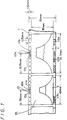
- a 35-mm photographic film 1 that can be used in a 35-mm photographic camera according to the present invention is described with reference to Figs. 1, 2, 3A, and 3B, in which Figs. 1 and 2 show 35-mm photographic film 1 after it has been exposed, and Figs. 3A and 3B show 35-mm photographic film 1 before it is exposed.
- the 35-mm photographic film 1 is stored in a film cartridge 16 and has an end extending out of the film cartridge 16. Images that are photographed on the 35-mm photographic film 1 are turned upside down by the lenses, so that the upper end of an image is positioned on a lower portion of the photographic film 1.
- Fig. 3B shows by way of example a photographed image of a subject in broken lines, which appears to be turned upside down on the photographic film 1.
- Each of the photographic films 1 shown in Figs. 1, 2, 3A, and 3B has a series of film position detecting holes 19 defined along an unexposed marginal edge area thereof, which has a width of about 2.5 mm.
- the film position detecting holes 19 have a diameter of about 1 mm and are spaced at a constant, predetermined pitch.
- the pitch of the film position detecting holes 19 in the photographic film 1 shown in Fig. 1 is 5.25 mm, for example, and the pitch of the film position detecting holes 19 in the photographic film 1 shown in Fig. 2 is 6.28 mm.
- the photographic film 1 shown in Fig. 3A has film position detecting holes 19 that will be positioned along an upper marginal edge area after the photographic film is exposed, however, no tongue is provided at the leading end, so that no tongue-removing process will subsequently be required. Because no tongue-removing process will be required, the subsequent processing of the photographic film 1 is less costly.
- the photographic film 1 shown in Fig. 3B also has film position detecting holes 19 that will be positioned in an upper marginal edge area thereof after the photographic film is exposed, and has a tongue at its leading end on its lower portion.
- the tongue at the leading end of the photographic film 1 is vertically opposite in position to the tongue of an ordinary 35-mm photographic film that is now generally commercially available. If a photocoupler is used in a photographic camera for detecting the film position detecting holes 19, then when the photographic film 1 is loaded into the photographic camera, the marginal edge with the film position detecting holes 19 is not required to be manually inserted into the photocoupler, but is automatically inserted into the photocoupler when the photographic film 1 is wound by a film transport mechanism in the photographic camera.
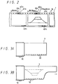
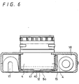
- FIG. 4 is a rear elevation of the photographic camera with the rear lid or removed.
- the lid is shown in Fig. 5.
- the photographic camera has a dark box 4 including a cartridge housing 17 for housing the film cartridge 16, which is of a known structure, an exposure opening 7 near the cartridge housing 17 and through which the photographic film 1 can be exposed to light passing through a camera lens, aperture, and shutter not shown in Fig. 4, and a film housing 18 for housing the photographic film 1 after it has been exposed.
- the photographic film 1 that is unwound from the film cartridge 16 housed in the cartridge housing 17 is fed over the exposure opening 7 while being transversely limited in motion by upper and lower respective pairs of film guides 30, 31, and is then moved into the film housing 18 after being exposed.
- the film housing 18 has a guide roller 32 for automatically setting or loading the photographic film 1, and a film takeup spool 9 rotatable by a motor, shown at 10 in Fig. 7, for winding the exposed photographic film 1 thereon.
- the photographic camera has a light-emitting diode (LED) 5a positioned between the lower film guides 30, 31 for detecting the film position detecting boles 19, and a photodetector, shown in Fig. 5 at 5b, disposed on a pressure plate of the rear lid and positioned in registry with the LED 5a across the photographic film 1.
- the photodetector 5b has a diameter of 1.5 mm, for example.
- the LED 5a emits infrared radiation having a wavelength of 940 nm, which is different from those radiation wavelengths to which the photographic film 1 is sensitive.
- the LED 5a and the photodetector 5b jointly make up a hole sensor 5 that applies an output signal to a counter in a system controller 8 that comprises a microcomputer. In this way, the system controller 8 can recognize the position of the photographic film 1 over the exposure opening 7.
- the LED 5a and the photodetector 5b may be alternatively replaced with a photocoupler that also comprises an LED and a photodetector but which are positioned in confronting relationship, as described hereinbelow.
- the exposure area opening 7 has its size defined by left and right movable masks 15 that are laterally movable over the width of the exposure opening 7 from opposite sides thereof.
- the size of the exposure opening 7 in the longitudinal direction of the photographic film 1 can selectively be changed to four different dimensions of 53.33 mm, 40.00 mm, 22.5 mm, and 16.90 mm as indicated by the four pairs of broken lines in Fig. 4.
- the left and right movable masks 15 are retractable into left and right side walls, respectively, that are positioned on opposite sides of the exposure opening 7 and extend substantially perpendicularly to the photographic film 1 as it extends over the exposure opening 7.
- two linear toothed bars 33 are attached to the respective lower edges of the movable masks 15 and held in mesh with respective drive feed gears 34 of a gearbox 35, much like a rack and pinion assembly.
- gears 34 of the gearbox 35 are driven to rotate the linear toothed bars 33, and hence the movable masks 15, are linearly moved over the exposure opening 7.
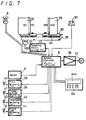
- the photographic camera has a frame size setting switch 6 which can manually be turned by the user of the camera to produce a command signal indicative of a selected frame size which is one of the frame sizes described above in Table 1.
- the frame size setting switch 6 applies a command signal to the system controller 8, which then supplies a control signal to achieve the desired frame size through a stepping motor driving circuit 13 to a stepping motor 14.
- the stepping motor 14 is energized to rotate the feed gears 34 to move the movable masks 15.
- the hole sensor 5 produces and supplies a detected film position signal to the system controller 8, which processes the supplied film position signal to generate a control signal.
- the system controller 8 then supplies the control signal through an amplifier 36 to a motor 10, which rotates the film spool 9 to take-up the photographic film 1 over a predetermined length.
- the length over which the photographic film 1 is driven corresponds to the distance that is determined by the frame size setting switch 6.
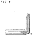
- the feeding of the photographic film 1 is described below with reference to Figs. 9A through 9B, which show examples in which the hole pitch is 6.28 mm and the photographic film 1 is to be exposed in an HDTV-matched full-frame size of 30 mm x 53.3 mm and an NTSC-matched full-frame size of 30 mm x 40 mm.
- Fig. 9A shows a portion of the photographic film 1 as it is exposed in successive NTSC-matched full frames.
- the photographic film 1 is fed for seven pitches of the holes 19, a frame area of 30 mm x 40 mm is made available for exposure through the exposure opening 7.
- the photographic film 1 is fed for eight pitches of the holes 19, as shown in Fig. 9B, to make a frame area of 30 mm x 53.3 mm available for exposure through the exposure opening 7.
- the photographic film 1 is fed for nine pitches of the holes 19, as shown in Fig.
- the photographic film 1 is fed for eight pitches of the holes 19, as shown in Fig. 9D, to make a frame area of 30 mm x 40 mm available for exposure through the exposure opening 7.
- the system controller 8 controls the motor 10 as follows: When switching from an NTSC-matched full-frame size to an HDTV-matched full-frame size, the photographic film 1 is first driven for seven pitches of the holes 19 and is then driven for one additional hole pitch. When switching from an HDTV-matched full-frame size to an NTSC-matched full-frame size, the photographic film 1 is first driven forward for nine pitches of the holes 19 and is then driven backward for one pitch.
- the photographic film 1 When changing frame sizes, the photographic film 1 may be driven for a different distance or a different number of pitches, such as ten pitches of the holes 19, as shown in Fig. 9E. In this manner, the photographic film 1 may be easily exposed in many different frame sizes.
- the system controller of the photographic camera controls the feeding of the photographic film 1 such that the photographic film 1 will not be exposed in overlapping frames, even when different frame sizes are exposed.
- Figs. 1 and 2 illustrate the photographic film 1 whose effective exposure areas have been exposed in frames 3 of different sizes.
- the photographic film 1 has been exposed in an HDTV-matched full-frame size, having a width of 30 mm, a length of 53.3 mm, and aspect ratio of 9:16, and in an NTSC-matched full-frame size, having a width of 30 mm, a length of 40 mm) whose aspect ratio is 3 : 4.
- the holes 19 defined along the upper marginal edge of the photographic film 1 have a pitch of 5.25 mm.
- the photographic film 1 has also been exposed in an HDTV-matched full-frame size and an NTSC-matched full-frame size, however, unlike Fig. 1, the holes 19 defined in the upper marginal edge of the photographic film 1 have a pitch of 6.28 mm.
- one frame of an HDTV-matched full-frame size corresponds nine pitches of the holes 19
- one frame of an NTSC-matched full-frame size corresponds seven pitches of the holes 19. Since these pitches are odd-numbered, a hole 19 may be positioned in alignment with the center of the frame, so that the center of the frame can easily be detected.
- the photographic camera has a shutter release button 37.
- the system controller 8 controls the size of the exposure area and supplies a control signal to a mark recording circuit 38 for recording a central mark, a so-called effective exposure area position signal, indicative of the center of the frame 3 and also supplies a control signal to a frame number recording circuit 39 for recording a frame number.
- the mark recording circuit 38 energizes an LED 40 positioned at the lower film-guide pair 30, 31 for recording a central mark 40a, shown in Figs. 1 and 2, representing the center of the exposed frame 3.
- the frame number recording circuit 39 energizes an LED 41 positioned at the lower film guide pair 30, 31 for recording a frame number 41a, shown in Figs. 1 and 2, representing the frame number of the exposed frame 3.
- the frame number 41a can be recorded such that it agrees with an actual frame number.
- the system controller 8 also supplies a control signal to a frame size recording circuit 11 for recording a frame size signal, a so-called effective exposure area width signal, indicative of the frame size of the exposed frame 3.
- the frame size recording circuit 11 energizes an LED 12 positioned at the lower film guide pair 30, 31 for recording a frame size signal 12a, shown in Figs. 1 and 2.
- the LED 12 may be composed of four LED elements which are selectively energized to record one of frame size signals 12a, which represent the frame size set by the frame size setting switch 6.
- the various frame size signals 12a are shown by way of example in Table 2 below.
- Table 2 Frame Size Frame size signal 12a HDTV-matched full-frame size
- the central mark 40a and the frame size signal 12a supply information regarding the frame position and the frame size to an automatic printer, described hereinbelow, for controlling the automatic printer when the exposed and processed film is printed.
- While frame sizes can be recognized by measuring the distances between adjacent central marks 40a when the exposed film is printed, the processing speed of the automatic printer can be increased by using the frame size signal 12a.
- the system controller 8 supplies an information signal to an information recording circuit 42 for recording desired information.
- the information recording circuit 42 energizes an LED 43 positioned at the upper film guide pair 30, 31 for recording such information 43a on the lower marginal edge, shown in see Figs. 1 and 2, of the photographic film 1.
- the information 43a may be information that is supplied from the camera lens and the camera itself upon exposure or could consist of the exposure date, the person who took the picture, an exposure condition, or other information that the user has entered through an input device 44, such as a keypad, on the outer surface of the rear lid of the camera body 10.
- the amount of information 43a is dependent upon the frame size, and is displayed on a display panel 44a of the input device 44.
- the LED 43 has a number of LED elements that are selectively energized depending on the frame size.
- the photographic camera according to the present invention has a detecting means 5a, 5b for detecting the feeding of the photographic film 1, a film control system 8, 9, 10 for controlling the distance by which the photographic film 1 moves and for driving the photographic film 1 for a length corresponding to the width of the selected exposure opening 7, based on a detected signal from the detecting means 5a, 5b, and for controlling a signal recording device 8, 11, 12, 38, 40 disposed near the exposure opening 7 for recording a signal indicative of the position of the exposure opening 7 on the photographic film 1 when the photographic film 1 is exposed through the exposure opening 7.
- the processed photographic film 1 After the photographic film 1 is exposed using the photographic camera, the processed photographic film 1 bears control signals that are recorded in a signal recording area 21, shown in see Fig. 1, thereof and that will be used when the photographic film 1 is printed. Therefore, even if the developed photographic film 1 contains frames of different frame sizes, it can be automatically printed by an automatic printer without requiring individual adjustment.
- the photographic camera according to the present invention also has a film control system 8, 9, 10 for controlling the feeding or driving of the photographic film 1, and an opening control system 8, 13, 14, 15 for varying the width of the exposure opening 7 along the photographic film 1. At least when the width of the exposure opening 7 changes from a smaller dimension to a larger dimension, the film control system 8, 9, 10 drives the photographic film 1 for a length corresponding to the selected width of the exposure opening 7.
- the width of the exposure opening 7 is variable, and the take-up or driving of the photographic film 1 is controlled depending on the width of the exposure opening 7.
- the photographic camera can expose the photographic film 1 successively in desired frame sizes which may differ one from another without adjacent frames overlapping each other.
- the photographic film 1 used in the photographic camera according to the present invention has a signal recording area 21 located between an effective exposure area 20 and a marginal edge thereof for recording control signals, which will be used when the photographic film 1 is processed and printed.
- the film 1 also has holes 19 defined in an upper marginal edge area thereof between the effective exposure area 20 and the marginal edge for detecting the distance by which the photographic film 1 has been moved.
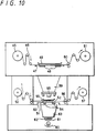
- an automatic printer for automatically printing processed photographic film 1 that has been exposed using a camera as described above has a printer body that supports a paper supply reel 45 for supplying the sensitized print paper 46, a paper deck or platen 47 for supporting the print paper 46 supplied from the paper supply reel 45, a variable paper mask 48 for determining the size of a print paper segment on which an image is to be printed, a paper holder plate 49 for holding the print paper 46 down against the paper deck 47, a paper feed or drive roller 50 for driving the print paper 46, and a paper takeup reel 51 for winding the exposed print paper 46.
- the printer body of the automatic printer also supports a film supply reel 52 for supplying the processed photographic film 1, a film deck or platen 53 for supporting the photographic film 1 supplied from the film supply reel 52, a negative-carrier variable slit 54, a negative holder plate 55 for positioning the negative down against the film deck 53, a film feed or drive roller 56 for driving the photographic film 1, a film takeup reel 57 for winding the exposed and processed photographic film 1, a lens 58 positioned above the negative holder plate 55, a bellows 59 supporting the lens 58 and positioned below the paper deck 47, a lamp 60 disposed below the film deck 53, a black shutter 61 positioned above the lamp 60, a filter assembly 62 composed of yellow, magenta, and cyan (Y, M, C) filters, and a diffusion box 63 disposed between the filter assembly 62 and the film deck 53.
- a film supply reel 52 for supplying the processed photographic film 1
- a film deck or platen 53 for supporting the photographic film 1 supplied from the film supply reel 52
- the negative holder plate 55 supports a frame size sensor S1 for detecting the frame size signal 12a recorded on the photographic film 1 and a frame center sensor S2 for detecting the central mark 40a recorded on the photographic film 1 that indicates the center of a frame.
- the film drive roller 56 Upon detection of the central mark 40a of the frame 3 with the frame center sensor S2, the film drive roller 56 is controlled to drive the film to align the frame center with the center of the negative-carrier variable slit 54.
- the variable paper mask 48 and the negative-carrier variable slit 54 are controlled based on the frame size signal 12a that is detected by the frame size sensor S1.
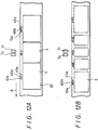
- the negative-carrier variable slit 54 is set to dimensions as shown in Fig. 14A, and the variable paper mask 48 is set to dimensions as shown in Fig. 15A.
- the frame size is an NTSC-matched frame size, for example, the negative-carrier variable slit 54 is set to dimensions as shown in Fig. 14B, and the variable paper mask 48 is set to dimensions as shown in Fig. 15B.
- FIG. 11 A control system for the automatic printer is shown in Fig. 11, in which the frame size sensor S1 and the frame center sensor S2 comprise photocouplers, respectively, for detecting the frame size signal 12a and the central mark 40a, respectively, that are recorded in the marginal edge area of the photographic film 1.
- the frame center is determined based on the central mark 40a detected by the frame center sensor S2, and the frame size of the frame 3 whose frame center is determined by a microprocessor 64 of the control system based on the frame size signal 12a that is read by the frame size sensor S1 before the central mark 40a is detected by the frame center sensor S2. Then, the microprocessor 64 controls a mask size drive motor M3 to actuate the variable paper mask 48 to conform with the determined frame size. At the same time, the microprocessor 64 controls a negative-carrier variable slit drive motor M2 to actuate the negative-carrier variable slit 54.
- the microprocessor 64 controls a film feed motor M1 to rotate the film feed roller 56 for feeding the photographic film 1 for a predetermined length.
- the microprocessor 64 controls a paper feed motor M4 to rotate the paper feed roller 50 for thereby feeding the print paper 46 for a predetermined length.
- Figs. 12A and 12B show the relationship between the photographic film 1, the frame center sensor S2, and the frame size sensor S1 in the automatic printer.
- a frame size signal 12a is detected by the frame size sensor S1 before its frame 3 is positioned for controlling of the driving of the photographic film 1, the negative-carrier variable slit 54, and the variable paper mask 48.
- the frame size signal 12a is processed by the microprocessor 64, which determines the frame size when the frame center of the frame 3 is determined.
- the central mark 40A indicative of a frame center is recorded at each frame on the photographic film 1.
- the frame size signal 12a is recorded ahead of the central mark 40a
- the frame number 41a is recorded behind the central mark 40a with respect to the direction in which the photographic film 1 is driven.
- frame center sensor S2 and the frame size sensor S1 are shown as being located in substantially the same position, only the frame center sensor S2 should be positioned in alignment with the center of the negative-carrier variable slit 54 and the variable paper mask 48, and the frame size sensor S1 may be positioned on the film deck 53 at the entrance end thereof.
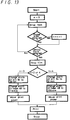
- Fig. 13 shows a control sequence of the micro-processor 64 for controlling the driving of the developed photographic film or negative 1 and the driving of the print paper 46.
- the negative-carrier variable slit 54 and the variable paper mask 48 are also controlled in this control sequence.
- the photographic film 1 is continuously driven and taken up until the central mark 40a is detected by the frame center sensor S2, and then the photographic film 1 is stopped when the central mark 40a is detected by the frame center sensor S2. Until the photographic film 1 is stopped, the frame size signal 12a is detected by the frame size sensor S1 and its number is counted.
- the width of the negative-carrier variable slit 54 is set to 38 mm, and the width of the variable paper mask 48 is set to 119 mm.
- the print paper 46 is moved, and the photographic film 1 is printed, after which the control sequence is ended.
- the print paper 46 is moved for a distance corresponding to printed frame sizes, a blank surrounding the printed frames, and a cutting blank between the printed frames.
- a hole is defined in the cutting blank when the photographic film 1 is printed, and serves as a positional signal for automatically cutting the print paper.
- the width of the negative-carrier variable slit 54 is set to 51 mm, and the width of the variable paper mask 48 is set to 158 mm. Thereafter, the print paper 46 is moved, and the photographic film 1 is printed, after which the control sequence is ended.
- the frame size signal 12a represents "1" or "2”
- the widths of the negative-carrier variable slit 54 and the variable paper mask 48 are set similarly. Thereafter, the print paper 46 is moved, and the photographic film 1 is printed, after which the control sequence is ended.
- the frame size signal 12a is recorded in the upper marginal edge portion of the photographic film 1, it may possibly be recognized in error as the central mark 40a.
- a negative feed sensor S3, shown in Fig. 11, for detecting the distance by which the photographic film 1 is fed is associated with the film feed motor M1, and the distance by which the photographic film 1 is fed is measured by a counter 65 whose count is fed back to the microprocessor 64. Since the width of the frame size signal 12a on the photographic film 1 can be detected by the distance by which the photographic film 1 is driven, the frame size signal 12a can be distinguished from the central mark 40a or the frame number 41a.
- the automatic printer according to the present invention has a film drive control device 65, 64, M1 for detecting an effective exposure area position signal 40a recorded in a marginal edge area between the effective exposure area 20 on the photographic film 1 and the marginal edge thereof to control the driving of the photographic film 1, and a printing opening width control device 54, 64, M2 for detecting an effective exposure area width indicating signal 12a recorded in the marginal edge area to control the width of the printing opening along the photographic film 1.
- the photographic film 1 has an effective exposure area position signal 40a and an effective exposure area width indicating signal 12a which are recorded in a marginal edge area between the effective exposure area 20 on the photographic film 1 and the marginal edge thereof. After the effective exposure area width indicating signal 12a has been detected, the effective exposure area position signal 40a is detected. The width of the film exposure opening along the photographic film 1, the width of the print paper exposure opening, and the distance by which the print paper 46 is driven are controlled based on the detected effective exposure area width indicating signal 12a, and the distance by which the photographic film 1 is fed is controlled based on the detected effective exposure area position signal 40a.
- the photographic film 1 can automatically be printed even if it has a succession of frames of different sizes.
- a photocoupler 66 which is an integral combination of an LED and a photodetector for detecting a film position, may be disposed on a film guide 30.
- the photocoupler 66 may be positioned anywhere on the film guide 30.
- the photocoupler 66 may have LEDs 41, 40, as shown in Fig. 4, for recording the frame number 41a and the central mark 40a at the same time that the frame is exposed.
- the hole sensor 5 comprises an LED and a photodetector in the illustrated photographic camera
- the hole sensor 5 may comprise two pairs of an LED and a photodetector given the different distances by which frames of different sizes are fed.
- the same photographic film contain frames of different sizes, however, the present invention is also applicable to an automatic printer for automatically printing a spliced length of photographic films with different frame sizes.
Abstract
Description
- The present invention relates to a photographic film for producing pictures having various frame sizes, and more particularly to unexposed and exposed photographic film and a film printing device for printing from the processed photographic film a succession of prints of different sizes that have been photographed by a camera.
- The photographic film that is in the most widespread use today is 35-mm film (system 135) as provided for by Japanese Industrial Standards (JIS) and International Organisation of Standardisation (IOS).
- U.S. Patent 5,049,908 describes a photographic camera and a film therefor, with the film being of a 35-mm size devoid of sprocket holes of the size used in present 35-mm films and having an effective image area of about 30 mm across the film, thereby providing an increased effective usable film area.
- More specifically, ignoring dimensional tolerances, present 35-mm films for use in general photography have a width of 35 mm between opposite longitudinal edges and include a series of film-transport perforations or sprocket holes defined along the opposite longitudinal edges of the film. The film-transport perforations are spaced 25 mm across the film and have a pitch of 4.75 mm. Frames on such a present 35-mm film are of a rectangular shape having a width of 25 mm across the film and a length of 36 mm along the film. The frames have a pitch of 38 mm, which is eight times larger than the pitch of the film-transport perforations.
- As described in U.S. Patent 5,049,908, some modern photographic film cameras are electronically controlled to provide motor-driven operation with high accuracy, and it has been experimentally confirmed that the film can be transported quite accurately without requiring the large sprocket wheels and film perforations that are found in most present cameras and films. In the system described in U.S. Patent 5,049,908, the film-transport perforations are not present in the 35-mm photographic film, thereby increasing the available frame width across the film up to the regions where such film-transport perforations were located. The proposed film thus has an increased effective image area for improved image quality. This patent describes four sizes that are available for frames that can be exposed on a 35-mm film free of film-transport perforations.
- According to one size, a frame that can be exposed in an effective image area of the 35-mm film has a width of 30 mm across the film and a length of 40 mm along the film. The frames of much a size have a pitch of 42.0 mm, for example. The frame size and pitch are selected to match specifications of the present television broadcasting system, for example, the NTSC system. Therefore, the frames have an aspect ratio of 3:4.
- Another frame size described in that patent is based on High-Definition Television (HDTV) specifications, in which frames have a width of 30 mm and a length of 53.3 mm and a pitch of 57.75 mm, for example. The aspect ratio of the frames having that size is 9:16.
- The above-mentioned frame sizes are full-frame sizes, and the other two frame sizes are half-frame sizes. According to one of the half-frame sizes, frames have a width of 30 mm and a length of 22.5 mm and a pitch of 26.2 mm, for example, to match present television broadcasting system specifications. According to the other half-frame size, frames have a width of 30 mm and a length of 16.9 mm and a pitch of 21.0 mm, for example, to match HDTV specifications.
- Film with the above four frame formats is stored in the same film cartridge as presently available 35-mm film.
- Because the frames in either of the above frame formats have a width of 30 mm, there are unexposed areas of about 2.5 mm between the frames and along the opposite longitudinal edges of the film. These unexposed areas may be used to keep the film flat, control the film, and write and read data when taking pictures.
- The proposed camera may be relatively small and lightweight, because it does not require film-transport sprocket wheels.
- Films that are actually collected in processing laboratories are processed either simultaneously in a batch or individually. In a simultaneous batch process, several thousand films are processed per hour at a high rate to realize economics of scale for reducing the printing cost. Specifically, a plurality of exposed films are collected in the processing laboratory and are spliced end to end to form a long, continuous film strip, which is then stored in a film magazine and subsequently processed.
- If the films that are spliced into the continuous strip contain frames exposed in different frame formats, such as disclosed in U.S. patent No. 5,049,908, then the long single film stored in the film magazine contains different frame sizes, thereby making printing a problem.
- U.S. Patents 4,384,774 and 5,066,971 propose cameras capable of switching between half and full frame sizes at the time the film is exposed. When film exposed using these proposed cameras is spliced into a long, single, film strip for simultaneous batch processing, the continuous film strip also contains different frame sizes.
- The processing laboratories are therefore required to form notches indicative of frame centers for automatically printing spliced films with different frame sizes after they are developed. For example, as disclosed in U.S. patent No. 4,557,591, a human operator manually notches a side edge of a spliced film and, hence, the notches are required to control the feed of the film. With the disclosed process, it is impossible to process several thousand films per hour, however, the cost of processing exposed film is relatively high. As a consequence, films with different frame sizes may not be accepted by processing laboratories in Japan.
- Many processing laboratories all over the world also do not accept films with frames exposed in half size because they do not want different frame sizes to be contained in a single spliced film that is stored in a single film magazine for subsequent processing and printing. This problem arises because the different frame sizes can be recognized only after the film has been developed. One solution would be to apply marking seals to exposed films so that the films of different frame sizes thereof can be distinguished and sorted out for individual processing and printing. Nevertheless, use of marking seals would not essentially solve the problem, because it would be difficult to supply such marking seals consistently over a number of years.
- Accordingly, it is an object of the present invention to provide a photographic film that can eliminate or reduce at least some of the above-noted drawbacks inherent in prior proposed systems.
- According to one aspect of the present invention, there is provided a photographic film for a photographic camera having a first housing, a second housing, a film feeder, a selector switch for enabling a user to select one of a set of aspect ratios for a photosensitive print paper, a control circuit connected to the selector switch, and a recording circuit for electrically receiving an aspect signal based upon the selection signal from the control circuit and recording the aspect signal and information signal, the photographic film comprising:
- a film strip;
- an effective exposure area disposed on the film strip to expose an image of an object thereon; and
- first and second regions along the film strip provided between edges of the film strip and the effective exposure area;
characterised in that - the regions are devoid of sprocket holes, the first region being used by the recording circuit for recording the information relating to the image exposed on the effective area, the second region having detection holes to be detected by a detector provided in the camera for controlling film feeding; and
- the effective exposure area matches HDTV format type having an aspect ratio of 16:9 and having a size of 30 mm x 16.9 mm.
- According to another aspect of the present invention, there is also provided an exposed photographic film comprising:
- first and second longitudinal marginal edge regions along the length of the film;
- an exposure area extending longitudinally along the length of the film between said first and second marginal regions and having discrete image exposures along its length; wherein
- said first marginal region has film position detecting holes along its length, used by a camera for positioning the film;
- each discrete image exposure has recorded beside it in one of the marginal regions, a set of image exposure information signals indicative of the position of its associated exposure image on the film strip and including information recorded on the film by a camera and being indicative of and resultant from the position of a photograph format setting switch as selected by a user when taking a photograph; and
- each of said discrete image exposures is one of a NTSC-matched frame size, HDTV-matched frame size, HDTV-matched half frame size and NTSC-matched half frame size.
- Preferably the present invention provides a photographic camera for use with a photographic film to provide an exposed photographic film as defined above, said camera comprising:
- a first housing for housing a photographic film cartridge housing said film;
- a second housing for housing photographic film drawn from the photographic film cartridge;
- a film feed device for feeding the photographic film between the first and second housings;
- an exposure device for exposing said exposure area to exposure images;
- a photograph format setting switch for use by the user of the camera to select the format of each photograph; and
- a recording device for recording in one of the marginal regions of a film, image exposure information signals indicative of the positions where the image exposures are formed on the exposure area and of the settings on the setting switch for each of the image exposures.
- The present invention also provides a printer for printing from the above-mentioned film.
- Other aspects of the invention are indicated in the following numbered statements.
- 1. A photographic system comprising:
- a photographic camera, including:
- a camera body,
- a first housing disposed in said camera body for housing unexposed photographic film in a cartridge,
- a second housing disposed in said camera body for housing the photographic film drawn from said photographic film cartridge,
- film drive means disposed in said camera body for driving the photographic film between said first and second housings,
- exposure area control means disposed in said camera body for controlling a size of an exposure area of the photographic film available to an image of a subject to be recorded on the photographic film, and
- recording means disposed in said camera body for recording on the photographic film an exposure position control signal indicative of a position of the exposure area on the photographic film controlled by said exposure area control means; and
- a photographic film printer for printing on photosensitive paper processed photographic film recorded using said photographic camera, including
- a printer body,
- a light source and variable width mask for exposing the photosensitive paper,
- detecting means disposed on said printer body for detecting said exposure position control signal recorded on the photographic film by said photographic camera,
- processed photographic film drive control means disposed on said printer body for controlling driving of the photographic film based on the exposure position control signal detected by said detecting means, and
- printing means disposed on said printer body for varying an opening width of said variable width mask used to expose the image of the subject in said exposure area of the photographic film on the photosensitive paper in response to detecting said exposure position control signal.
- 2. A photographic camera system according to 1, wherein said exposure area control means comprises means for varying a dimension of the exposure area of the photographic film in a direction in which the photographic film is driven by said film drive means.
- 3. A photographic camera system according to 2, wherein said exposure position control signal includes an exposure area position signal and an exposure area size signal, and wherein said processed photographic film drive control means comprises means for controlling driving of the photographic film in response to detecting said exposure area position signal, and said printing means comprises means for varying said opening width of said variable width mask in response to detecting said exposure area size signal.
- 4. A photographic camera system according to 2 or 3, wherein said means for varying a dimension comprises left and right movable masks, mounted on said camera body for respective movement in said direction of film drive and opposite to said direction.
- 5. A photographic camera system according to 4, wherein said means for varying further comprises linear gear elements affixed to ends of said left and right movable masks cooperating with respective rotary gears and motor means for rotating said rotary gears to drive said linear gear elements.
- 6. A photographic camera system according to 5, wherein said exposure area control means further includes a frame signal setting switch for selecting at least two exposure area sizes, and wherein said motor means comprises a stepper motor driver for driving said left and right movable masks to at least two predetermined positions corresponding to said at least two exposure area sizes.
- 7. A photographic camera system according to 6, wherein one of said at least two exposure area sizes includes an exposure area dimension of 53.33 mm.
- 8. A photographic camera system according to 1, 2, 3, 4, 5, 6 or 7, wherein said photographic film printer further comprises a negative feed sensor for detecting a distance the photographic film is driven by said film drive control means, and a logic circuit receiving an output of said negative feed sensor for determining that said detecting means correctly detected said exposure position control signal.
- 9. A photographic camera comprising:
- a first housing for housing a photographic film cartridge containing a photographic film strip;
- a second housing for housing a photographic film strip drawn from said cartridge;
- film feed means for feeding the photographic film between said first and second housings;
- exposure area control means for producing a control signal fed to said film feed means for controlling a size of an exposure area on the photographic film fed by said film feed means available to record an image of a subject; and
- recording means for recording an exposure position control signal indicative of a position where the photographic film is to be exposed by said exposure means on the photographic film.
- 10. A photographic camera according to 9, wherein said exposure means comprises means for varying a dimension of the exposure area of the photographic film is exposed to the image of the subject in a direction in which the photographic film strip is fed by said film feed means.
- 11. A photographic camera according to 10, wherein said recording means includes means for producing said exposure position control signal to include an exposure area position signal and an exposure area size signal.
- 12. A photographic camera according to 11, wherein said recording means includes means for producing said exposure area position signal to include an exposure area central position signal and an exposure area number indicating signal.
- 13. A photographic camera system according to 10, 11 or 12 wherein said means for varying a dimension comprises left and right movable masks, mounted on said camera body for respective movement in said direction of film drive and opposite to said direction.
- 14. A photographic camera system according to 13, wherein said means for varying further comprises linear gear elements affixed to ends of said left and right movable masks cooperating with respective rotary gears and motor means for rotating said rotary gears to drive said linear gear elements.
- 15. A photographic camera system according to 14, wherein said exposure area control means further includes a frame signal setting switch for selecting at least two exposure area sizes, and wherein said motor means comprises a stepper motor driver for driving said left and right movable masks to at least two predetermined positions corresponding to said at least two exposure area sizes.
- 16. A photographic camera system according to 6 or 15, wherein one of said at least two exposure area sizes includes an exposure area dimension of 53.33 mm.
- 17. A photographic camera comprising:
- a camera body;
- a first housing disposed in said camera body for housing a photographic film cartridge containing a photographic film strip;
- a second housing disposed in said camera body for housing the photographic film strip drawn from said photographic film cartridge;
- film feed means disposed in said camera body for feeding the photographic film between said first and second housings;
- exposure means disposed in said camera body for varying a dimension of an exposure area in which the photographic film is exposed to an image of a subject in a direction in which the photographic film is fed by said film feed means between said first and second housings; and
- control means disposed in said camera body for controlling said film feed means to feed the photographic film for length corresponding to an increase in said dimension at least when said width is increased.
- 18. A photographic film printer comprising:
- a printer body;
- detecting means disposed on said printer body for detecting an exposure position control signal recorded on a photographic film;
- film feed control means disposed on said printer body for controlling feeding of the photographic film based on the exposure position control signal detected by sad detecting means; and
- printing means disposed on said printer body for varying an opening width of a mask which is used to print an image of a subject in an exposure area of the photographic film on a print paper, depending on said exposure position control signal.
- 19. A photographic film printer according to 18, wherein said exposure position control signal comprises an exposure area position signal and an exposure area size signal, and wherein said film feed control means comprises means for controlling feeding of the photographic film based on said exposure area position signal, and said printing means comprises means for varying said opening width of the mask based on said exposure area size signal.
- 20. A photographic film printer according to 18 or 19, wherein said printing means comprises means for feeding the print paper for a length corresponding to an increase in said opening width at least when said opening width is increased.
- 21. A photographic film printer according to 18, 19 or 20, further comprising a negative feed sensor for detecting a distance the photographic film is fed independently of said exposure position control signal, and a logic circuit receiving an output of said negative feed sensor for determining that said detecting means correctly detected said exposure position control signal.
- 22. A photographic camera including a first housing for housing a photographic film cartridge, a second housing for housing a photographic film drawn from the photographic film cartridge, a film feed device for feeding the photographic film between the first and second housings, an exposure device for exposing an exposure area of the photographic film fed by the film feed device to an image of the subject and a recording device for recording an exposure position control signal indicative of a position where the photographic film is to be exposed by the exposure device on the photographic film.
- The invention will be further described by way of non-limitative example with reference to the accompanying drawings, in which:-
- Fig. 1 is a fragmentary front elevational view of a 35-mm film that has been exposed using a 35-mm photographic camera according to an embodiment of the present invention;
- Fig. 2 is a fragmentary front elevational view of another 35-mm film that has been exposed using an embodiment of the 35-mm photographic camera of the present invention;
- Figs. 3A and 3B are elevational views of 35-mm film cartridges that can be used in the 35-mm photographic camera embodiment of the present invention;
- Fig. 4 is a rear elevational view of the 35-mm photographic camera of the embodiment of the present invention with a rear lid removed;
- Fig. 5 is an elevational view of an inner surface of a rear lid of the 35-mm photographic camera of Fig. 4;
- Fig. 6 is a cross-sectional view taken along line VI - VI of Fig. 4;
- Fig. 7 is a block diagram of a control system used in the embodiment of the 35-mm photographic camera according to the present invention;
- Fig. 8 is an enlarged fragmentary view of a portion of the camera shown in Fig. 6;
- Figs. 9A through 9B are fragmentary front elevational views showing the positional relationships of frames exposed on a 35-mm film using the embodiment of the 35-mm photographic camera according to the present invention;
- Fig. 10 is an elevational view of an automatic printer for printing on photosensitive paper a 35-mm film exposed using the embodiment Of the 35-mm photographic camera according to the present invention;
- Fig. 11 is a block diagram of a control system used in the embodiment of the automatic printer shown in Fig. 10;
- Figs. 12A and 12B are fragmentary front elevational views showing the relationship between a 35-mm film and sensors in the automatic printer shown in Fig. 10;
- Fig. 13 is a flowchart of an operating method that is performed by a microprocessor of the control system shown in Fig. 11;
- Figs. 14A and 14B are representative of the relative sizes of negative-carrier variable slits in the automatic printer;
- Figs. 15A and 15B are representation showing the relative sizes of variable paper masks in the automatic printer;
- Fig. 16 is a rear elevational view of a 35-mm photographic camera with a rear lid removed, according to another embodiment of the present invention; and
- Fig. 17 is a rear elevational view of a 35-mm photographic camera with a rear lid removed, according to still another embodiment of the present invention.
- A 35-mm
photographic film 1 that can be used in a 35-mm photographic camera according to the present invention is described with reference to Figs. 1, 2, 3A, and 3B, in which Figs. 1 and 2 show 35-mmphotographic film 1 after it has been exposed, and Figs. 3A and 3B show 35-mmphotographic film 1 before it is exposed. - As shown in Figs. 3A and 3B, the 35-mm
photographic film 1 is stored in afilm cartridge 16 and has an end extending out of thefilm cartridge 16. Images that are photographed on the 35-mmphotographic film 1 are turned upside down by the lenses, so that the upper end of an image is positioned on a lower portion of thephotographic film 1. Fig. 3B shows by way of example a photographed image of a subject in broken lines, which appears to be turned upside down on thephotographic film 1. - Each of the
photographic films 1 shown in Figs. 1, 2, 3A, and 3B has a series of filmposition detecting holes 19 defined along an unexposed marginal edge area thereof, which has a width of about 2.5 mm. The filmposition detecting holes 19 have a diameter of about 1 mm and are spaced at a constant, predetermined pitch. The pitch of the filmposition detecting holes 19 in thephotographic film 1 shown in Fig. 1 is 5.25 mm, for example, and the pitch of the filmposition detecting holes 19 in thephotographic film 1 shown in Fig. 2 is 6.28 mm. - Distances by which the different
photographic films 1 with the filmposition detecting holes 19 spaced at the pitches of 5.25 mm and 6.28 mm are advanced to feed frames of different frame sizes are given in Table 1 below.Table 1 Frame sizes (Width x length) Pitch = 6.28 mm Pitch = 5.25 mm NTSC-matched frame size (30 mm x 40 mm), full size 43.96 = 6.28 x 7 pitches 42.0 = 5.25 x 8 pitches HDTV-matched frame size (30 mm x 53.3 mm), full size 56.52 = 6.28 x 9 pitches 57.75 = 5.25 x 11 pitches HDTV-matched frame size (30 mm x 16.9 mm), half size 18.84 = 6.28 x 3 pitches 21.0 = 5.25 x 4 pitches NTSC-matched frame size (30 mm x 22.5 mm), half size 25.12 = 6.28 x 4 pitches 26.25 = 5.25 x 5 pitches - The
photographic film 1 shown in Fig. 3A has filmposition detecting holes 19 that will be positioned along an upper marginal edge area after the photographic film is exposed, however, no tongue is provided at the leading end, so that no tongue-removing process will subsequently be required. Because no tongue-removing process will be required, the subsequent processing of thephotographic film 1 is less costly. - The
photographic film 1 shown in Fig. 3B also has filmposition detecting holes 19 that will be positioned in an upper marginal edge area thereof after the photographic film is exposed, and has a tongue at its leading end on its lower portion. The tongue at the leading end of thephotographic film 1 is vertically opposite in position to the tongue of an ordinary 35-mm photographic film that is now generally commercially available. If a photocoupler is used in a photographic camera for detecting the filmposition detecting holes 19, then when thephotographic film 1 is loaded into the photographic camera, the marginal edge with the filmposition detecting holes 19 is not required to be manually inserted into the photocoupler, but is automatically inserted into the photocoupler when thephotographic film 1 is wound by a film transport mechanism in the photographic camera. - An embodiment of a photographic camera that can use the
photographic films 1 shown in Figs. 1, 2, 3A, and 3B is shown and described with reference to Figs. 4 through 8. Fig. 4 is a rear elevation of the photographic camera with the rear lid or removed. The lid is shown in Fig. 5. The photographic camera has adark box 4 including acartridge housing 17 for housing thefilm cartridge 16, which is of a known structure, anexposure opening 7 near thecartridge housing 17 and through which thephotographic film 1 can be exposed to light passing through a camera lens, aperture, and shutter not shown in Fig. 4, and afilm housing 18 for housing thephotographic film 1 after it has been exposed. - The
photographic film 1 that is unwound from thefilm cartridge 16 housed in thecartridge housing 17 is fed over theexposure opening 7 while being transversely limited in motion by upper and lower respective pairs of film guides 30, 31, and is then moved into thefilm housing 18 after being exposed. - The
film housing 18 has aguide roller 32 for automatically setting or loading thephotographic film 1, and afilm takeup spool 9 rotatable by a motor, shown at 10 in Fig. 7, for winding the exposedphotographic film 1 thereon. - The photographic camera has a light-emitting diode (LED) 5a positioned between the lower film guides 30, 31 for detecting the film
position detecting boles 19, and a photodetector, shown in Fig. 5 at 5b, disposed on a pressure plate of the rear lid and positioned in registry with theLED 5a across thephotographic film 1. Thephotodetector 5b has a diameter of 1.5 mm, for example. - The
LED 5a emits infrared radiation having a wavelength of 940 nm, which is different from those radiation wavelengths to which thephotographic film 1 is sensitive. Referring to Fig. 7, theLED 5a and thephotodetector 5b jointly make up ahole sensor 5 that applies an output signal to a counter in asystem controller 8 that comprises a microcomputer. In this way, thesystem controller 8 can recognize the position of thephotographic film 1 over theexposure opening 7. TheLED 5a and thephotodetector 5b may be alternatively replaced with a photocoupler that also comprises an LED and a photodetector but which are positioned in confronting relationship, as described hereinbelow. - In Fig. 4, the
exposure area opening 7 has its size defined by left and rightmovable masks 15 that are laterally movable over the width of the exposure opening 7 from opposite sides thereof. The size of theexposure opening 7 in the longitudinal direction of thephotographic film 1 can selectively be changed to four different dimensions of 53.33 mm, 40.00 mm, 22.5 mm, and 16.90 mm as indicated by the four pairs of broken lines in Fig. 4. - As shown in Figs. 6 and 8, the left and right
movable masks 15 are retractable into left and right side walls, respectively, that are positioned on opposite sides of theexposure opening 7 and extend substantially perpendicularly to thephotographic film 1 as it extends over theexposure opening 7. As shown in Fig. 7, two linear toothed bars 33 are attached to the respective lower edges of themovable masks 15 and held in mesh with respective drive feed gears 34 of a gearbox 35, much like a rack and pinion assembly. When thegears 34 of the gearbox 35 are driven to rotate the linear toothed bars 33, and hence themovable masks 15, are linearly moved over theexposure opening 7. - As shown in Figs. 4 and 7, the photographic camera has a frame
size setting switch 6 which can manually be turned by the user of the camera to produce a command signal indicative of a selected frame size which is one of the frame sizes described above in Table 1. When the user selects a frame size with the framesize setting switch 6, the framesize setting switch 6 applies a command signal to thesystem controller 8, which then supplies a control signal to achieve the desired frame size through a steppingmotor driving circuit 13 to a steppingmotor 14. The steppingmotor 14 is energized to rotate the feed gears 34 to move the movable masks 15. At the same time that themovable masks 15 move, thehole sensor 5 produces and supplies a detected film position signal to thesystem controller 8, which processes the supplied film position signal to generate a control signal. Thesystem controller 8 then supplies the control signal through anamplifier 36 to amotor 10, which rotates thefilm spool 9 to take-up thephotographic film 1 over a predetermined length. - At this time, the length over which the
photographic film 1 is driven corresponds to the distance that is determined by the framesize setting switch 6. The feeding of thephotographic film 1 is described below with reference to Figs. 9A through 9B, which show examples in which the hole pitch is 6.28 mm and thephotographic film 1 is to be exposed in an HDTV-matched full-frame size of 30 mm x 53.3 mm and an NTSC-matched full-frame size of 30 mm x 40 mm. - Fig. 9A shows a portion of the
photographic film 1 as it is exposed in successive NTSC-matched full frames. When thephotographic film 1 is fed for seven pitches of theholes 19, a frame area of 30 mm x 40 mm is made available for exposure through theexposure opening 7. To switch from an NTSC-matched full-frame size to an HDTV-matched full-frame size, thephotographic film 1 is fed for eight pitches of theholes 19, as shown in Fig. 9B, to make a frame area of 30 mm x 53.3 mm available for exposure through theexposure opening 7. To expose thephotographic film 1 in successive HDTV-matched full frames, thephotographic film 1 is fed for nine pitches of theholes 19, as shown in Fig. 9C, to make a frame area of 30 mm x 53.3 mm available for exposure through theexposure opening 7. To switch from an HDTV-matched full-frame size to an NTSC-matched full-frame size, thephotographic film 1 is fed for eight pitches of theholes 19, as shown in Fig. 9D, to make a frame area of 30 mm x 40 mm available for exposure through theexposure opening 7. - To change frame sizes, the
system controller 8 controls themotor 10 as follows: When switching from an NTSC-matched full-frame size to an HDTV-matched full-frame size, thephotographic film 1 is first driven for seven pitches of theholes 19 and is then driven for one additional hole pitch. When switching from an HDTV-matched full-frame size to an NTSC-matched full-frame size, thephotographic film 1 is first driven forward for nine pitches of theholes 19 and is then driven backward for one pitch. - When changing frame sizes, the
photographic film 1 may be driven for a different distance or a different number of pitches, such as ten pitches of theholes 19, as shown in Fig. 9E. In this manner, thephotographic film 1 may be easily exposed in many different frame sizes. - As shown in Figs. 9A through 9E, the system controller of the photographic camera controls the feeding of the
photographic film 1 such that thephotographic film 1 will not be exposed in overlapping frames, even when different frame sizes are exposed. - Figs. 1 and 2 illustrate the
photographic film 1 whose effective exposure areas have been exposed inframes 3 of different sizes. In Fig. 1, thephotographic film 1 has been exposed in an HDTV-matched full-frame size, having a width of 30 mm, a length of 53.3 mm, and aspect ratio of 9:16, and in an NTSC-matched full-frame size, having a width of 30 mm, a length of 40 mm) whose aspect ratio is 3 : 4. Theholes 19 defined along the upper marginal edge of thephotographic film 1 have a pitch of 5.25 mm. - In Fig. 2, the
photographic film 1 has also been exposed in an HDTV-matched full-frame size and an NTSC-matched full-frame size, however, unlike Fig. 1, theholes 19 defined in the upper marginal edge of thephotographic film 1 have a pitch of 6.28 mm. In Fig. 2, one frame of an HDTV-matched full-frame size corresponds nine pitches of theholes 19, and one frame of an NTSC-matched full-frame size corresponds seven pitches of theholes 19. Since these pitches are odd-numbered, ahole 19 may be positioned in alignment with the center of the frame, so that the center of the frame can easily be detected. - As shown in Figs. 4 and 7, the photographic camera has a
shutter release button 37. When theshutter release button 37 is depressed, thesystem controller 8 controls the size of the exposure area and supplies a control signal to amark recording circuit 38 for recording a central mark, a so-called effective exposure area position signal, indicative of the center of theframe 3 and also supplies a control signal to a framenumber recording circuit 39 for recording a frame number. Themark recording circuit 38 energizes anLED 40 positioned at the lower film-guide pair central mark 40a, shown in Figs. 1 and 2, representing the center of the exposedframe 3. The framenumber recording circuit 39 energizes anLED 41 positioned at the lowerfilm guide pair frame number 41a, shown in Figs. 1 and 2, representing the frame number of the exposedframe 3. Theframe number 41a can be recorded such that it agrees with an actual frame number. - The
system controller 8 also supplies a control signal to a framesize recording circuit 11 for recording a frame size signal, a so-called effective exposure area width signal, indicative of the frame size of the exposedframe 3. The framesize recording circuit 11 energizes anLED 12 positioned at the lowerfilm guide pair frame size signal 12a, shown in Figs. 1 and 2. - The
LED 12 may be composed of four LED elements which are selectively energized to record one offrame size signals 12a, which represent the frame size set by the framesize setting switch 6. The variousframe size signals 12a are shown by way of example in Table 2 below.Table 2 Frame Size Frame size signal 12aHDTV-matched full-frame size |||| NTSC-matched full-frame size ||| NTSC-matched half-frame size || HDTV-matched half-frame size | - The
central mark 40a and theframe size signal 12a supply information regarding the frame position and the frame size to an automatic printer, described hereinbelow, for controlling the automatic printer when the exposed and processed film is printed. - While frame sizes can be recognized by measuring the distances between adjacent
central marks 40a when the exposed film is printed, the processing speed of the automatic printer can be increased by using theframe size signal 12a. - At the same time that the
photographic film 1 is exposed, thesystem controller 8 supplies an information signal to aninformation recording circuit 42 for recording desired information. Theinformation recording circuit 42 energizes anLED 43 positioned at the upperfilm guide pair such information 43a on the lower marginal edge, shown in see Figs. 1 and 2, of thephotographic film 1. Theinformation 43a may be information that is supplied from the camera lens and the camera itself upon exposure or could consist of the exposure date, the person who took the picture, an exposure condition, or other information that the user has entered through aninput device 44, such as a keypad, on the outer surface of the rear lid of thecamera body 10. The amount ofinformation 43a, that is, the number of characters that can be recorded, is dependent upon the frame size, and is displayed on a display panel 44a of theinput device 44. TheLED 43 has a number of LED elements that are selectively energized depending on the frame size. - An analysis has been made to determine the optimum position where the
information 43a should be recorded and the optimum position where theholes 19 are defined from the standpoints of the user's convenience and a psychological effect that those positions have on the user. The results of the analysis are as follows: - (1) If marginal edges outside of the effective exposure area of the film are available as a band for recording user's information, then the information should more preferably be positioned on the lower marginal edge of the print paper, rather than on the upper marginal edge.
- (2) Study of the developing and printing processes in processing laboratories indicates that in many cases information about the film itself is printed in many cases on film negatives, such that the film information will be positioned on the upper marginal edge of the print paper. It is preferable not to mix the film information and the band for recording user's information.
- From the above results, it is preferable to position the film
position detecting holes 19 upwardly of the effective exposure area of the film when it is exposed. - As described above with reference to Figs. 4 through 7, the photographic camera according to the present invention has a detecting
means photographic film 1, afilm control system photographic film 1 moves and for driving thephotographic film 1 for a length corresponding to the width of the selectedexposure opening 7, based on a detected signal from the detectingmeans signal recording device exposure opening 7 for recording a signal indicative of the position of the exposure opening 7 on thephotographic film 1 when thephotographic film 1 is exposed through theexposure opening 7. - After the
photographic film 1 is exposed using the photographic camera, the processedphotographic film 1 bears control signals that are recorded in asignal recording area 21, shown in see Fig. 1, thereof and that will be used when thephotographic film 1 is printed. Therefore, even if the developedphotographic film 1 contains frames of different frame sizes, it can be automatically printed by an automatic printer without requiring individual adjustment. - The photographic camera according to the present invention also has a
film control system photographic film 1, and anopening control system exposure opening 7 along thephotographic film 1. At least when the width of the exposure opening 7 changes from a smaller dimension to a larger dimension, thefilm control system photographic film 1 for a length corresponding to the selected width of theexposure opening 7. - Therefore, the width of the
exposure opening 7 is variable, and the take-up or driving of thephotographic film 1 is controlled depending on the width of theexposure opening 7. The photographic camera can expose thephotographic film 1 successively in desired frame sizes which may differ one from another without adjacent frames overlapping each other. - As shown in Fig. 1, the
photographic film 1 used in the photographic camera according to the present invention has asignal recording area 21 located between aneffective exposure area 20 and a marginal edge thereof for recording control signals, which will be used when thephotographic film 1 is processed and printed. Thefilm 1 also hasholes 19 defined in an upper marginal edge area thereof between theeffective exposure area 20 and the marginal edge for detecting the distance by which thephotographic film 1 has been moved. - As shown in Fig. 10, an automatic printer for automatically printing processed
photographic film 1 that has been exposed using a camera as described above has a printer body that supports apaper supply reel 45 for supplying the sensitizedprint paper 46, a paper deck orplaten 47 for supporting theprint paper 46 supplied from thepaper supply reel 45, avariable paper mask 48 for determining the size of a print paper segment on which an image is to be printed, apaper holder plate 49 for holding theprint paper 46 down against thepaper deck 47, a paper feed or driveroller 50 for driving theprint paper 46, and apaper takeup reel 51 for winding the exposedprint paper 46. - The printer body of the automatic printer also supports a
film supply reel 52 for supplying the processedphotographic film 1, a film deck orplaten 53 for supporting thephotographic film 1 supplied from thefilm supply reel 52, a negative-carrier variable slit 54, anegative holder plate 55 for positioning the negative down against thefilm deck 53, a film feed or driveroller 56 for driving thephotographic film 1, afilm takeup reel 57 for winding the exposed and processedphotographic film 1, alens 58 positioned above thenegative holder plate 55, a bellows 59 supporting thelens 58 and positioned below thepaper deck 47, alamp 60 disposed below thefilm deck 53, ablack shutter 61 positioned above thelamp 60, afilter assembly 62 composed of yellow, magenta, and cyan (Y, M, C) filters, and adiffusion box 63 disposed between thefilter assembly 62 and thefilm deck 53. - The
negative holder plate 55 supports a frame size sensor S1 for detecting theframe size signal 12a recorded on thephotographic film 1 and a frame center sensor S2 for detecting thecentral mark 40a recorded on thephotographic film 1 that indicates the center of a frame. - Upon detection of the
central mark 40a of theframe 3 with the frame center sensor S2, thefilm drive roller 56 is controlled to drive the film to align the frame center with the center of the negative-carrier variable slit 54. Thevariable paper mask 48 and the negative-carrier variable slit 54 are controlled based on theframe size signal 12a that is detected by the frame size sensor S1. - If the frame size is an HDTV-matched frame size, for example, the negative-carrier variable slit 54 is set to dimensions as shown in Fig. 14A, and the
variable paper mask 48 is set to dimensions as shown in Fig. 15A. If the frame size is an NTSC-matched frame size, for example, the negative-carrier variable slit 54 is set to dimensions as shown in Fig. 14B, and thevariable paper mask 48 is set to dimensions as shown in Fig. 15B. - A control system for the automatic printer is shown in Fig. 11, in which the frame size sensor S1 and the frame center sensor S2 comprise photocouplers, respectively, for detecting the
frame size signal 12a and thecentral mark 40a, respectively, that are recorded in the marginal edge area of thephotographic film 1. - The frame center is determined based on the
central mark 40a detected by the frame center sensor S2, and the frame size of theframe 3 whose frame center is determined by amicroprocessor 64 of the control system based on theframe size signal 12a that is read by the frame size sensor S1 before thecentral mark 40a is detected by the frame center sensor S2. Then, themicroprocessor 64 controls a mask size drive motor M3 to actuate thevariable paper mask 48 to conform with the determined frame size. At the same time, themicroprocessor 64 controls a negative-carrier variable slit drive motor M2 to actuate the negative-carrier variable slit 54. - Based on the frame size signal 12A read by the frame size sensor S1, the
microprocessor 64 controls a film feed motor M1 to rotate thefilm feed roller 56 for feeding thephotographic film 1 for a predetermined length. At the same time, themicroprocessor 64 controls a paper feed motor M4 to rotate thepaper feed roller 50 for thereby feeding theprint paper 46 for a predetermined length. - Figs. 12A and 12B show the relationship between the
photographic film 1, the frame center sensor S2, and the frame size sensor S1 in the automatic printer. When thephotographic film 1 is driven in the direction indicated by the arrow A in Fig. 12A, aframe size signal 12a is detected by the frame size sensor S1 before itsframe 3 is positioned for controlling of the driving of thephotographic film 1, the negative-carrier variable slit 54, and thevariable paper mask 48. Theframe size signal 12a is processed by themicroprocessor 64, which determines the frame size when the frame center of theframe 3 is determined. - As shown in Figs. 12A and 12B, the central mark 40A indicative of a frame center is recorded at each frame on the
photographic film 1. At each frame, theframe size signal 12a is recorded ahead of thecentral mark 40a, and theframe number 41a is recorded behind thecentral mark 40a with respect to the direction in which thephotographic film 1 is driven. - While the frame center sensor S2 and the frame size sensor S1 are shown as being located in substantially the same position, only the frame center sensor S2 should be positioned in alignment with the center of the negative-carrier variable slit 54 and the
variable paper mask 48, and the frame size sensor S1 may be positioned on thefilm deck 53 at the entrance end thereof. - Fig. 13 shows a control sequence of the micro-processor 64 for controlling the driving of the developed photographic film or negative 1 and the driving of the
print paper 46. The negative-carrier variable slit 54 and thevariable paper mask 48 are also controlled in this control sequence. Thephotographic film 1 is continuously driven and taken up until thecentral mark 40a is detected by the frame center sensor S2, and then thephotographic film 1 is stopped when thecentral mark 40a is detected by the frame center sensor S2. Until thephotographic film 1 is stopped, theframe size signal 12a is detected by the frame size sensor S1 and its number is counted. - If the
frame size signal 12a represents "3", the width of the negative-carrier variable slit 54 is set to 38 mm, and the width of thevariable paper mask 48 is set to 119 mm. Thereafter, theprint paper 46 is moved, and thephotographic film 1 is printed, after which the control sequence is ended. Theprint paper 46 is moved for a distance corresponding to printed frame sizes, a blank surrounding the printed frames, and a cutting blank between the printed frames. Usually, a hole is defined in the cutting blank when thephotographic film 1 is printed, and serves as a positional signal for automatically cutting the print paper. - If the
frame size signal 12a represents "4", the width of the negative-carrier variable slit 54 is set to 51 mm, and the width of thevariable paper mask 48 is set to 158 mm. Thereafter, theprint paper 46 is moved, and thephotographic film 1 is printed, after which the control sequence is ended. - If the
frame size signal 12a represents "1" or "2", the widths of the negative-carrier variable slit 54 and thevariable paper mask 48 are set similarly. Thereafter, theprint paper 46 is moved, and thephotographic film 1 is printed, after which the control sequence is ended. - Since the
frame size signal 12a is recorded in the upper marginal edge portion of thephotographic film 1, it may possibly be recognized in error as thecentral mark 40a. To avoid such on error, a negative feed sensor S3, shown in Fig. 11, for detecting the distance by which thephotographic film 1 is fed is associated with the film feed motor M1, and the distance by which thephotographic film 1 is fed is measured by acounter 65 whose count is fed back to themicroprocessor 64. Since the width of theframe size signal 12a on thephotographic film 1 can be detected by the distance by which thephotographic film 1 is driven, theframe size signal 12a can be distinguished from thecentral mark 40a or theframe number 41a. - As described above with reference to Figs. 10, 11, and 12, the automatic printer according to the present invention has a film
drive control device area position signal 40a recorded in a marginal edge area between theeffective exposure area 20 on thephotographic film 1 and the marginal edge thereof to control the driving of thephotographic film 1, and a printing openingwidth control device width indicating signal 12a recorded in the marginal edge area to control the width of the printing opening along thephotographic film 1. - The
photographic film 1 has an effective exposurearea position signal 40a and an effective exposure areawidth indicating signal 12a which are recorded in a marginal edge area between theeffective exposure area 20 on thephotographic film 1 and the marginal edge thereof. After the effective exposure areawidth indicating signal 12a has been detected, the effective exposurearea position signal 40a is detected. The width of the film exposure opening along thephotographic film 1, the width of the print paper exposure opening, and the distance by which theprint paper 46 is driven are controlled based on the detected effective exposure areawidth indicating signal 12a, and the distance by which thephotographic film 1 is fed is controlled based on the detected effective exposurearea position signal 40a. - Therefore, since the distance by which the
photographic film 1 is driven is controlled based on the effective exposurearea position signal 40a recorded in the marginal edge area of thephotographic film 1 and the width of the printing opening, the width of the print paper exposure opening and the distance over which theprint paper 46 is driven are controlled based on the effective exposure areawidth indicating signal 12a recorded in the marginal edge area of thephotographic film 1, thephotographic film 1 can automatically be printed even if it has a succession of frames of different sizes. - In the illustrated photographic camera, the
LED 5a and thephotodetector 5b are disposed in confronting relationship to each other for detecting the filmposition detecting holes 19, however, as shown in Figs. 16 and 17, aphotocoupler 66, which is an integral combination of an LED and a photodetector for detecting a film position, may be disposed on afilm guide 30. Thephotocoupler 66 may be positioned anywhere on thefilm guide 30. Thephotocoupler 66 may haveLEDs frame number 41a and thecentral mark 40a at the same time that the frame is exposed. - While the
hole sensor 5 comprises an LED and a photodetector in the illustrated photographic camera, thehole sensor 5 may comprise two pairs of an LED and a photodetector given the different distances by which frames of different sizes are fed. - In the illustrated automatic printer, the same photographic film contain frames of different sizes, however, the present invention is also applicable to an automatic printer for automatically printing a spliced length of photographic films with different frame sizes.
- Having described preferred embodiments of the invention with reference to the accompanying drawings, it is to be understood that the invention is not limited to those precise embodiments and various changes and modifications could be effected by one skilled in the art without departing from the scope of the present invention, as defined in the appended claims.
Claims (10)
- A photographic film for a photographic camera having a first housing, a second housing, a film feeder, a selector switch for enabling a user to select one of a set of aspect ratios for a photosensitive print paper, a control circuit connected to the selector switch, and a recording circuit for electrically receiving an aspect signal based upon the selection signal from the control circuit and recording the aspect signal and information signal, the photographic film comprising:a film strip;an effective exposure area disposed on the film strip to expose an image of an object thereon; andfirst and second regions along the film strip provided between edges of the film strip and the effective exposure area;
characterised in thatthe regions are devoid of sprocket holes, the first region being used by the recording circuit for recording the information relating to the image exposed on the effective area, the second region having detection holes to be detected by a detector provided in the camera for controlling film feeding; andthe effective exposure area matches HDTV format type having an aspect ratio of 16:9 and having a size of 30 mm x 16.9 mm. - A photographic film according to claim 1, wherein one of the first and second regions being used by the recording circuit for recording the aspect signal relating to the image exposed on the effective exposure area for printing.
- An exposed photographic film comprising:first and second longitudinal marginal edge regions along the length of the film;an exposure area extending longitudinally along the length of the film between said first and second marginal regions and having discrete image exposures along its length; whereinsaid first marginal region has film position detecting holes along its length, used by a camera for positioning the film;each discrete image exposure has recorded beside it in one of the marginal regions, a set of image exposure information signals indicative of the position of its associated exposure image on the film strip and including information recorded on the film by a camera and being indicative of and resultant from the position of a photograph format setting switch as selected by a user when taking a photograph; andeach of said discrete image exposures is one of a NTSC-matched frame size, HDTV-matched frame size, HDTV-matched half frame size and NTSC-matched half frame size.
- A photographic camera for use with a photographic film to provide an exposed photographic film as defined in claim 3, said camera comprising:a first housing for housing a photographic film cartridge housing said film;a second housing for housing photographic film drawn from the photographic film cartridge;a film feed device for feeding the photographic film between the first and second housings;an exposure device for exposing said exposure area to exposure images;a photograph format setting switch for use by the user of the camera to select the format of each photograph; anda recording device for recording in one of the marginal regions of a film, image exposure information signals indicative of the positions where the image exposures are formed on the exposure area and of the settings on the setting switch for each of the image exposures.
- A photographic camera according to claim 4, loaded with a photographic film according to claim 1, 2 or 3.
- A photographic printer arranged to print different sized prints from an exposed photographic film according to claim 3.
- A photographic printer arranged to print different sized prints from an exposed photographic film exposed by a camera according to claim 4.
- A photographic printer according to claim 6 in combination with an exposed photographic film according to claim 3.
- A photographic printer according to claim 7 in combination with a film exposed by a camera according to claim 4.
- A photographic system comprising a photographic camera according to claim 4 or 5 in combination with a photographic printer according to any one of claims 6 to 9.
Applications Claiming Priority (7)
| Application Number | Priority Date | Filing Date | Title |
|---|---|---|---|
| JP6068492 | 1992-03-17 | ||
| JP6068492A JPH05265089A (en) | 1992-03-17 | 1992-03-17 | Photographic film camera and photographic film |
| JP60684/92 | 1992-03-17 | ||
| JP65304/92 | 1992-03-23 | ||
| JP6530492 | 1992-03-23 | ||
| JP6530492A JPH05265099A (en) | 1992-03-23 | 1992-03-23 | Device and method for printing film |
| EP93301948A EP0561592B1 (en) | 1992-03-17 | 1993-03-15 | Photographic film printer |
Related Parent Applications (2)
| Application Number | Title | Priority Date | Filing Date |
|---|---|---|---|
| EP93301948.1 Division | 1993-03-15 | ||
| EP93301948A Division EP0561592B1 (en) | 1992-03-17 | 1993-03-15 | Photographic film printer |
Publications (3)
| Publication Number | Publication Date |
|---|---|
| EP0840164A2 true EP0840164A2 (en) | 1998-05-06 |
| EP0840164A3 EP0840164A3 (en) | 1998-11-04 |
| EP0840164B1 EP0840164B1 (en) | 2004-11-03 |
Family
ID=26401743
Family Applications (7)
| Application Number | Title | Priority Date | Filing Date |
|---|---|---|---|
| EP98101733A Expired - Lifetime EP0840164B1 (en) | 1992-03-17 | 1993-03-15 | Photographic film |
| EP98101735A Expired - Lifetime EP0843204B1 (en) | 1992-03-17 | 1993-03-15 | Photographic film printer |
| EP00112579A Expired - Lifetime EP1035429B1 (en) | 1992-03-17 | 1993-03-15 | Photographic film printing |
| EP93301948A Expired - Lifetime EP0561592B1 (en) | 1992-03-17 | 1993-03-15 | Photographic film printer |
| EP99125862A Ceased EP0989448A3 (en) | 1992-03-17 | 1993-03-15 | Photographic camera and film |
| EP98101734A Ceased EP0843200A3 (en) | 1992-03-17 | 1993-03-15 | Photographic camera |
| EP00115631A Withdrawn EP1054291A1 (en) | 1992-03-17 | 1993-03-15 | Photograhpic film printer |
Family Applications After (6)
| Application Number | Title | Priority Date | Filing Date |
|---|---|---|---|
| EP98101735A Expired - Lifetime EP0843204B1 (en) | 1992-03-17 | 1993-03-15 | Photographic film printer |
| EP00112579A Expired - Lifetime EP1035429B1 (en) | 1992-03-17 | 1993-03-15 | Photographic film printing |
| EP93301948A Expired - Lifetime EP0561592B1 (en) | 1992-03-17 | 1993-03-15 | Photographic film printer |
| EP99125862A Ceased EP0989448A3 (en) | 1992-03-17 | 1993-03-15 | Photographic camera and film |
| EP98101734A Ceased EP0843200A3 (en) | 1992-03-17 | 1993-03-15 | Photographic camera |
| EP00115631A Withdrawn EP1054291A1 (en) | 1992-03-17 | 1993-03-15 | Photograhpic film printer |
Country Status (3)
| Country | Link |
|---|---|
| US (4) | US5625430A (en) |
| EP (7) | EP0840164B1 (en) |
| DE (5) | DE69320395D1 (en) |
Families Citing this family (19)
| Publication number | Priority date | Publication date | Assignee | Title |
|---|---|---|---|---|
| US5600386A (en) * | 1992-03-17 | 1997-02-04 | Sony Corporation | Photographic camera system |
| US5752114A (en) * | 1992-03-17 | 1998-05-12 | Sony Corporation | Photographic and video image system |
| US6115558A (en) * | 1992-03-17 | 2000-09-05 | Sony Corporation | Photographic camera system |
| US5570147A (en) * | 1992-03-17 | 1996-10-29 | Sony Corporation | Photographic camera system |
| US6600880B2 (en) | 1992-03-17 | 2003-07-29 | Sony Corporation | Photographic camera system |
| US6151456A (en) * | 1993-03-04 | 2000-11-21 | Sony Corporation | Photographic camera system |
| US6470152B2 (en) | 1992-03-17 | 2002-10-22 | Sony Corporation | Photographic and video image system |
| US5652643A (en) * | 1992-03-17 | 1997-07-29 | Sony Corporation | Photographic and video image system |
| US6006042A (en) * | 1992-03-17 | 1999-12-21 | Sony Corporation | Photographic camera system |
| US6583851B2 (en) | 1992-03-17 | 2003-06-24 | Sony Corporation | Photographic and video image system |
| EP0840164B1 (en) * | 1992-03-17 | 2004-11-03 | Sony Corporation | Photographic film |
| US5872619A (en) * | 1996-09-19 | 1999-02-16 | Eastman Kodak Company | Method and apparatus for printing zoomed photographs from negatives with pseudo zoomed widths |
| US5897232A (en) * | 1996-09-19 | 1999-04-27 | Eastman Kodak Company | Camera with widthwise pseudo zoom masks and method of exposing a pseudo zoom image |
| US6249652B1 (en) * | 1997-11-13 | 2001-06-19 | Fuji Photo Film Co., Ltd. | Lens-fitted photo film unit and method of producing photographic print |
| AT407444B (en) * | 1998-03-03 | 2001-03-26 | Bauer Fritz | FILM CAMERA WITH INFORMATION RECORDING |
| JP2001028459A (en) * | 1999-05-13 | 2001-01-30 | Sumitomo Electric Ind Ltd | Light-emitting device and its manufacture |
| EP1830552A1 (en) | 1999-12-28 | 2007-09-05 | Sony Corporation | Image commercial transactions system and method |
| EP1670233A1 (en) | 1999-12-28 | 2006-06-14 | Sony Corporation | A photographic image commercial transaction system using a portable music player |
| US7190473B1 (en) | 2000-07-05 | 2007-03-13 | Sherry Anderson Cook | Printer apparatus with integrated graphical user interface and method for using the same |
Citations (9)
| Publication number | Priority date | Publication date | Assignee | Title |
|---|---|---|---|---|
| JPH01282530A (en) * | 1988-05-09 | 1989-11-14 | Canon Inc | Camera for recording print size information |
| JPH01282533A (en) * | 1988-05-09 | 1989-11-14 | Canon Inc | Printing device capable of automatically changing aspect ratio of print |
| EP0357355A2 (en) * | 1988-08-31 | 1990-03-07 | Sony Corporation | Photographic camera |
| US4908641A (en) * | 1989-05-09 | 1990-03-13 | Eastman Kodak Company | Photographic film and film cassette |
| US4974096A (en) * | 1988-10-07 | 1990-11-27 | Eastman Kodak Company | Photofinishing process with film-to-video printer using dedicated magnetic tracks on film |
| US5005031A (en) * | 1988-10-07 | 1991-04-02 | Eastman Kodak Company | Camera apparatus for magnetically recording on film |
| EP0428072A2 (en) * | 1989-11-13 | 1991-05-22 | Fuji Photo Film Co., Ltd. | Data-retainable photographic film cartridge |
| US5066971A (en) * | 1986-10-09 | 1991-11-19 | Canon Kabushiki Kaisha | Camera |
| US5086311A (en) * | 1989-12-18 | 1992-02-04 | Fuji Photo Film Co., Ltd. | Panoramic camera |
Family Cites Families (42)
| Publication number | Priority date | Publication date | Assignee | Title |
|---|---|---|---|---|
| US2377341A (en) * | 1941-10-22 | 1945-06-05 | Clement E Hannum | Camera and the like |
| US3490844A (en) * | 1967-06-12 | 1970-01-20 | Eastman Kodak Co | Method of making a print of a selected portion or zone of a field of view |
| US3674365A (en) * | 1969-10-22 | 1972-07-04 | Agfa Gevaert Ag | Photographic printing apparatus |
| DE2545488A1 (en) * | 1975-10-10 | 1977-04-21 | Agfa Gevaert Ag | PRE-VIEWING DEVICE FOR A PHOTOGRAPHIC COPY DEVICE |
| JPS5853325B2 (en) * | 1979-03-19 | 1983-11-29 | 大日本スクリ−ン製造株式会社 | Edging mask device for printing equipment with automatic correction function |
| JPS5748729A (en) * | 1980-09-09 | 1982-03-20 | Copal Co Ltd | Automatic photograph printing device |
| US4482924A (en) * | 1982-09-29 | 1984-11-13 | Eastman Kodak Company | Video player, film medium, and photographic printer for automatic cropping |
| JPS60144078A (en) * | 1983-12-30 | 1985-07-30 | Fuji Photo Film Co Ltd | Method and apparatus for forming video signal of photographic picture |
| JPS6183526A (en) * | 1984-10-01 | 1986-04-28 | Fuji Photo Film Co Ltd | Trimming printing device |
| US4693591A (en) * | 1985-08-05 | 1987-09-15 | Minolta Camera Kabushiki Kaisha | Microfilm and microfilm printer |
| US4650304A (en) * | 1985-08-15 | 1987-03-17 | Eastman Kodak Company | Pseudo format camera and special film cartridge |
| DE3529363A1 (en) * | 1985-08-16 | 1987-02-19 | Schloemann Siemag Ag | ADJUSTMENT DEVICE FOR THE AXIAL PARALLEL SHIFTING OF ROLLS OF A ROLLING DEVICE |
| US4860039A (en) * | 1985-10-31 | 1989-08-22 | Minolta Camera Kabushiki Kaisha | Photographic camera system and using thereof |
| US5245373A (en) * | 1986-07-22 | 1993-09-14 | Canon Kabushiki Kaisha | Data imprinting device for camera |
| JPS6388542A (en) * | 1986-10-01 | 1988-04-19 | Canon Inc | Image recorder |
| US4737825A (en) * | 1986-11-14 | 1988-04-12 | Davis Robert C | Printer with traversing lens and printing method |
| JPH01282536A (en) * | 1988-05-09 | 1989-11-14 | Canon Inc | Printing device capable of automatically changing print size |
| US5151726A (en) * | 1987-05-09 | 1992-09-29 | Canon Kabushiki Kaisha | Camera or printer capable of automatically changing print size |
| JPS6452634A (en) * | 1987-05-09 | 1989-02-28 | Kubota Ltd | Crystallized glass material and production thereof |
| JP2832351B2 (en) * | 1988-04-27 | 1998-12-09 | コニカ株式会社 | Photo printing machine trimming device |
| JP2705103B2 (en) * | 1988-05-16 | 1998-01-26 | 富士ゼロックス株式会社 | Paper feeder in image forming apparatus |
| JPH0833586B2 (en) * | 1988-05-27 | 1996-03-29 | 富士写真フイルム株式会社 | Photo printing equipment with monitor |
| US4977419A (en) * | 1988-10-07 | 1990-12-11 | Eastman Kodak Company | Self-clocking encoding/decoding film information exchange system using dedicated magnetic tracks on film |
| US4965627A (en) * | 1988-10-07 | 1990-10-23 | Eastman Kodak Company | Film information exchange system using dedicated magnetic tracks on film with virtual data indentifiers |
| US5229810A (en) * | 1988-10-07 | 1993-07-20 | Eastman Kodak Company | Film information exchange system using dedicated magnetic tracks on film |
| DE69024549T2 (en) * | 1989-07-25 | 1996-06-13 | Minolta Camera Kk | Image reproduction system |
| US5072253A (en) * | 1989-09-05 | 1991-12-10 | Eastman Kodak Company | Ordering and recording information system for business and greeting cards |
| JPH0469639A (en) * | 1990-07-10 | 1992-03-04 | Nikon Corp | Photography completion information recording device for camera |
| JPH04119776A (en) * | 1990-09-11 | 1992-04-21 | Sony Corp | Solid-state image pickup device |
| EP0503510B1 (en) * | 1991-03-08 | 1997-06-04 | Fuji Photo Film Co., Ltd. | Photographic film package |
| JPH0519368A (en) * | 1991-07-11 | 1993-01-29 | Fuji Photo Film Co Ltd | Printed photograph preparing method and photographic film cartridge, camera, and photographic printer, used in the method |
| US5274422A (en) * | 1991-07-12 | 1993-12-28 | Fuji Photo Film Co., Ltd. | Print processing method |
| US5249056A (en) * | 1991-07-16 | 1993-09-28 | Sony Corporation Of America | Apparatus for generating video signals from film |
| JPH05181209A (en) * | 1991-09-20 | 1993-07-23 | Fuji Photo Film Co Ltd | Information recording and reading method and device therefor |
| JPH05249551A (en) * | 1992-03-06 | 1993-09-28 | Canon Inc | Camera using film with magnetic storage part |
| US5570147A (en) * | 1992-03-17 | 1996-10-29 | Sony Corporation | Photographic camera system |
| EP0840164B1 (en) * | 1992-03-17 | 2004-11-03 | Sony Corporation | Photographic film |
| US5600386A (en) * | 1992-03-17 | 1997-02-04 | Sony Corporation | Photographic camera system |
| US5583591A (en) * | 1992-03-17 | 1996-12-10 | Sony Corporation | Photographic camera system |
| US5652643A (en) * | 1992-03-17 | 1997-07-29 | Sony Corporation | Photographic and video image system |
| US5752114A (en) * | 1992-03-17 | 1998-05-12 | Sony Corporation | Photographic and video image system |
| US5526255A (en) * | 1994-08-31 | 1996-06-11 | Polaroid Corporation | True zoom capability on a spot scanning electronic printer |
-
1993
- 1993-03-15 EP EP98101733A patent/EP0840164B1/en not_active Expired - Lifetime
- 1993-03-15 DE DE69320395A patent/DE69320395D1/en not_active Expired - Fee Related
- 1993-03-15 EP EP98101735A patent/EP0843204B1/en not_active Expired - Lifetime
- 1993-03-15 DE DE69333685T patent/DE69333685T2/en not_active Expired - Fee Related
- 1993-03-15 DE DE69333967T patent/DE69333967T2/en not_active Expired - Fee Related
- 1993-03-15 EP EP00112579A patent/EP1035429B1/en not_active Expired - Lifetime
- 1993-03-15 DE DE69333158T patent/DE69333158T2/en not_active Expired - Fee Related
- 1993-03-15 EP EP93301948A patent/EP0561592B1/en not_active Expired - Lifetime
- 1993-03-15 EP EP99125862A patent/EP0989448A3/en not_active Ceased
- 1993-03-15 EP EP98101734A patent/EP0843200A3/en not_active Ceased
- 1993-03-15 DE DE69320395T patent/DE69320395T4/en not_active Expired - Lifetime
- 1993-03-15 EP EP00115631A patent/EP1054291A1/en not_active Withdrawn
-
1994
- 1994-11-02 US US08/333,593 patent/US5625430A/en not_active Expired - Lifetime
-
1997
- 1997-05-05 US US08/851,412 patent/US5752109A/en not_active Expired - Fee Related
-
1998
- 1998-05-07 US US09/074,291 patent/US6122452A/en not_active Expired - Fee Related
-
1999
- 1999-10-22 US US09/422,717 patent/US6061529A/en not_active Expired - Fee Related
Patent Citations (9)
| Publication number | Priority date | Publication date | Assignee | Title |
|---|---|---|---|---|
| US5066971A (en) * | 1986-10-09 | 1991-11-19 | Canon Kabushiki Kaisha | Camera |
| JPH01282530A (en) * | 1988-05-09 | 1989-11-14 | Canon Inc | Camera for recording print size information |
| JPH01282533A (en) * | 1988-05-09 | 1989-11-14 | Canon Inc | Printing device capable of automatically changing aspect ratio of print |
| EP0357355A2 (en) * | 1988-08-31 | 1990-03-07 | Sony Corporation | Photographic camera |
| US4974096A (en) * | 1988-10-07 | 1990-11-27 | Eastman Kodak Company | Photofinishing process with film-to-video printer using dedicated magnetic tracks on film |
| US5005031A (en) * | 1988-10-07 | 1991-04-02 | Eastman Kodak Company | Camera apparatus for magnetically recording on film |
| US4908641A (en) * | 1989-05-09 | 1990-03-13 | Eastman Kodak Company | Photographic film and film cassette |
| EP0428072A2 (en) * | 1989-11-13 | 1991-05-22 | Fuji Photo Film Co., Ltd. | Data-retainable photographic film cartridge |
| US5086311A (en) * | 1989-12-18 | 1992-02-04 | Fuji Photo Film Co., Ltd. | Panoramic camera |
Non-Patent Citations (2)
| Title |
|---|
| PATENT ABSTRACTS OF JAPAN vol. 14, no. 59 (P [1000], 2 February 1990 & JP 01 282530 A (CANON INC.), 14 November 1989 * |
| PATENT ABSTRACTS OF JAPAN vol. 14, no. 59 (P [1000], 2 February 1990 & JP 01 282533 A (CANON INC.), 14 November 1989 * |
Also Published As
| Publication number | Publication date |
|---|---|
| EP1035429A3 (en) | 2000-09-27 |
| EP0989448A2 (en) | 2000-03-29 |
| DE69320395T2 (en) | 1999-03-04 |
| DE69333967T2 (en) | 2006-10-05 |
| DE69333967D1 (en) | 2006-04-13 |
| EP0843204A3 (en) | 1998-11-04 |
| EP0561592A1 (en) | 1993-09-22 |
| EP0840164A3 (en) | 1998-11-04 |
| US5752109A (en) | 1998-05-12 |
| EP0840164B1 (en) | 2004-11-03 |
| US6061529A (en) | 2000-05-09 |
| DE69333158T2 (en) | 2004-08-12 |
| EP0843200A3 (en) | 1998-11-04 |
| EP1035429A2 (en) | 2000-09-13 |
| DE69333158D1 (en) | 2003-09-25 |
| EP1035429B1 (en) | 2006-01-25 |
| EP0843204A2 (en) | 1998-05-20 |
| EP0989448A3 (en) | 2000-05-31 |
| DE69320395D1 (en) | 1998-09-24 |
| EP0561592B1 (en) | 1998-08-19 |
| US5625430A (en) | 1997-04-29 |
| EP0843200A2 (en) | 1998-05-20 |
| US6122452A (en) | 2000-09-19 |
| EP0843204B1 (en) | 2003-08-20 |
| DE69320395T4 (en) | 2001-05-03 |
| EP1054291A1 (en) | 2000-11-22 |
| DE69333685T2 (en) | 2005-10-27 |
| DE69333685D1 (en) | 2004-12-09 |
Similar Documents
| Publication | Publication Date | Title |
|---|---|---|
| EP1076258B1 (en) | Photographic printer with adjustable mask | |
| US6035143A (en) | Photographic camera system | |
| EP0840164B1 (en) | Photographic film | |
| US5960220A (en) | Photographic camera system | |
| US5758215A (en) | Photographic camera system | |
| US6154616A (en) | Photographic camera system | |
| US6078757A (en) | Photographic camera system | |
| US6600880B2 (en) | Photographic camera system | |
| USRE36877E (en) | Photographic camera system | |
| USRE36753E (en) | Photographic camera system | |
| JP3541347B2 (en) | Photographic system and photographic film printing device | |
| JP3603218B2 (en) | Photographic system and photographic film printing device |
Legal Events
| Date | Code | Title | Description |
|---|---|---|---|
| PUAI | Public reference made under article 153(3) epc to a published international application that has entered the european phase |
Free format text: ORIGINAL CODE: 0009012 |
|
| AC | Divisional application: reference to earlier application |
Ref document number: 561592 Country of ref document: EP |
|
| AK | Designated contracting states |
Kind code of ref document: A2 Designated state(s): DE FR GB |
|
| PUAL | Search report despatched |
Free format text: ORIGINAL CODE: 0009013 |
|
| AK | Designated contracting states |
Kind code of ref document: A3 Designated state(s): DE FR GB |
|
| 17P | Request for examination filed |
Effective date: 19981109 |
|
| 17Q | First examination report despatched |
Effective date: 20000627 |
|
| GRAJ | Information related to disapproval of communication of intention to grant by the applicant or resumption of examination proceedings by the epo deleted |
Free format text: ORIGINAL CODE: EPIDOSDIGR1 |
|
| GRAP | Despatch of communication of intention to grant a patent |
Free format text: ORIGINAL CODE: EPIDOSNIGR1 |
|
| GRAP | Despatch of communication of intention to grant a patent |
Free format text: ORIGINAL CODE: EPIDOSNIGR1 |
|
| GRAS | Grant fee paid |
Free format text: ORIGINAL CODE: EPIDOSNIGR3 |
|
| GRAA | (expected) grant |
Free format text: ORIGINAL CODE: 0009210 |
|
| AC | Divisional application: reference to earlier application |
Ref document number: 0561592 Country of ref document: EP Kind code of ref document: P |
|
| AK | Designated contracting states |
Kind code of ref document: B1 Designated state(s): DE FR GB |
|
| REG | Reference to a national code |
Ref country code: GB Ref legal event code: FG4D |
|
| REF | Corresponds to: |
Ref document number: 69333685 Country of ref document: DE Date of ref document: 20041209 Kind code of ref document: P |
|
| PLBE | No opposition filed within time limit |
Free format text: ORIGINAL CODE: 0009261 |
|
| STAA | Information on the status of an ep patent application or granted ep patent |
Free format text: STATUS: NO OPPOSITION FILED WITHIN TIME LIMIT |
|
| ET | Fr: translation filed | ||
| 26N | No opposition filed |
Effective date: 20050804 |
|
| PGFP | Annual fee paid to national office [announced via postgrant information from national office to epo] |
Ref country code: GB Payment date: 20090311 Year of fee payment: 17 |
|
| PGFP | Annual fee paid to national office [announced via postgrant information from national office to epo] |
Ref country code: DE Payment date: 20090313 Year of fee payment: 17 |
|
| PGFP | Annual fee paid to national office [announced via postgrant information from national office to epo] |
Ref country code: FR Payment date: 20090316 Year of fee payment: 17 |
|
| GBPC | Gb: european patent ceased through non-payment of renewal fee |
Effective date: 20100315 |
|
| REG | Reference to a national code |
Ref country code: FR Ref legal event code: ST Effective date: 20101130 |
|
| PG25 | Lapsed in a contracting state [announced via postgrant information from national office to epo] |
Ref country code: FR Free format text: LAPSE BECAUSE OF NON-PAYMENT OF DUE FEES Effective date: 20100331 |
|
| PG25 | Lapsed in a contracting state [announced via postgrant information from national office to epo] |
Ref country code: DE Free format text: LAPSE BECAUSE OF NON-PAYMENT OF DUE FEES Effective date: 20101001 |
|
| PG25 | Lapsed in a contracting state [announced via postgrant information from national office to epo] |
Ref country code: GB Free format text: LAPSE BECAUSE OF NON-PAYMENT OF DUE FEES Effective date: 20100315 |