EP0839999B1 - Einrichtung zur Beseitigung des Verschlusses der in die Brennkammer von Staustrahltriebwerken einmündenden Lufteinlaufkanäle - Google Patents
Einrichtung zur Beseitigung des Verschlusses der in die Brennkammer von Staustrahltriebwerken einmündenden Lufteinlaufkanäle Download PDFInfo
- Publication number
- EP0839999B1 EP0839999B1 EP97402549A EP97402549A EP0839999B1 EP 0839999 B1 EP0839999 B1 EP 0839999B1 EP 97402549 A EP97402549 A EP 97402549A EP 97402549 A EP97402549 A EP 97402549A EP 0839999 B1 EP0839999 B1 EP 0839999B1
- Authority
- EP
- European Patent Office
- Prior art keywords
- flap
- shut
- combustion chamber
- ramjet
- combustion
- Prior art date
- Legal status (The legal status is an assumption and is not a legal conclusion. Google has not performed a legal analysis and makes no representation as to the accuracy of the status listed.)
- Expired - Lifetime
Links
- 238000002485 combustion reaction Methods 0.000 title claims description 81
- 239000007789 gas Substances 0.000 claims description 19
- 239000000446 fuel Substances 0.000 claims description 10
- 239000003570 air Substances 0.000 description 27
- 239000003380 propellant Substances 0.000 description 16
- 238000002347 injection Methods 0.000 description 4
- 239000007924 injection Substances 0.000 description 4
- 239000012080 ambient air Substances 0.000 description 2
- 229910000831 Steel Inorganic materials 0.000 description 1
- 241001080024 Telles Species 0.000 description 1
- 240000008042 Zea mays Species 0.000 description 1
- 238000013459 approach Methods 0.000 description 1
- 238000012550 audit Methods 0.000 description 1
- 239000000567 combustion gas Substances 0.000 description 1
- 230000001066 destructive effect Effects 0.000 description 1
- 230000009977 dual effect Effects 0.000 description 1
- 230000000694 effects Effects 0.000 description 1
- 238000010304 firing Methods 0.000 description 1
- 239000007788 liquid Substances 0.000 description 1
- 230000000149 penetrating effect Effects 0.000 description 1
- 229920001296 polysiloxane Polymers 0.000 description 1
- 239000000843 powder Substances 0.000 description 1
- 230000002028 premature Effects 0.000 description 1
- 239000011253 protective coating Substances 0.000 description 1
- 238000007789 sealing Methods 0.000 description 1
- 239000012781 shape memory material Substances 0.000 description 1
- 239000004449 solid propellant Substances 0.000 description 1
- 230000002269 spontaneous effect Effects 0.000 description 1
- 239000010959 steel Substances 0.000 description 1
Images

Classifications
-
- F—MECHANICAL ENGINEERING; LIGHTING; HEATING; WEAPONS; BLASTING
- F02—COMBUSTION ENGINES; HOT-GAS OR COMBUSTION-PRODUCT ENGINE PLANTS
- F02K—JET-PROPULSION PLANTS
- F02K7/00—Plants in which the working fluid is used in a jet only, i.e. the plants not having a turbine or other engine driving a compressor or a ducted fan; Control thereof
- F02K7/10—Plants in which the working fluid is used in a jet only, i.e. the plants not having a turbine or other engine driving a compressor or a ducted fan; Control thereof characterised by having ram-action compression, i.e. aero-thermo-dynamic-ducts or ram-jet engines
- F02K7/18—Composite ram-jet/rocket engines
-
- Y—GENERAL TAGGING OF NEW TECHNOLOGICAL DEVELOPMENTS; GENERAL TAGGING OF CROSS-SECTIONAL TECHNOLOGIES SPANNING OVER SEVERAL SECTIONS OF THE IPC; TECHNICAL SUBJECTS COVERED BY FORMER USPC CROSS-REFERENCE ART COLLECTIONS [XRACs] AND DIGESTS
- Y02—TECHNOLOGIES OR APPLICATIONS FOR MITIGATION OR ADAPTATION AGAINST CLIMATE CHANGE
- Y02T—CLIMATE CHANGE MITIGATION TECHNOLOGIES RELATED TO TRANSPORTATION
- Y02T50/00—Aeronautics or air transport
- Y02T50/60—Efficient propulsion technologies, e.g. for aircraft
Definitions
- the present invention relates to ramjet engines, as well as aerial mobiles, such as missiles or the like, powered by such a ramjet. It relates more particularly a closure system for an orifice air inlet into the combustion chamber of a ramjet.
- ramjet engines are essentially made up by a combustion chamber, ending with a ejection nozzle and inside which are introduced liquid or gaseous fuel (which can be generated from solid fuel) and combustion air.
- This combustion air is introduced into said combustion chamber through at least one orifice of the wall of said combustion chamber and capturing air (or receiving it through a sleeve of air intake) when said ramjet (or the mobile carrying it) moves relative to the ambient air.
- Such dual mode operation requires to provide a shutter system to, on the one hand, seal said air introduction orifice during rocket operation, in order to avoid leakage, through said orifice, of the gases generated by said auxiliary consumable propellant and, on the other hand, open said introduction orifice of air for operation as a ramjet itself.
- said hatch can pass from its closed position to its open position under the spontaneous action of said elastic system, without need an auxiliary control system.
- the action of said elastic system has the same meaning as that of the difference of pressures applied to both sides of the hatch.
- the ramjet is mounted on a missile flying at low or medium altitude, the hatch opens under the combined action of said elastic system and the pressure difference, while, if said missile flies at very high altitude, the opening of said hatch practically only results from the sole action of said elastic system.
- said hatch is tiltable and it is integral in rotation of a shaft rotatably mounted on said combustion chamber.
- said system elastic comprises a torsion bar, in engagement with said rotary hatch shaft.
- This one and said bar twist can be arranged parallel to the axis of said combustion chamber. They can even be coaxial.
- said rotary shaft is eccentric relative to to said tilting hatch, and the part of said hatch the larger with respect to said eccentric axis pivots towards said combustion chamber, when said hatch passes from its closed position to its open position. So, the gases generated by said auxiliary propellant can exert on said hatch an action tending to press this in its closed position.
- said orifice air inlet is surrounded by a protruding neck outward of said combustion chamber and said tilting hatch and its rotating shaft are arranged in said col.
- Said retainer which can be a destructible link such as a steel cable, can be placed on the side of said hatch opposite to said combustion chamber and we can provide at least one channel crossing said hatch on the other hand in part, to submit said retainer to action gases generated by the auxiliary propellant. So the gas at high temperature generated by it and passing through said channel can break said link, so that said torsion bar, as it unwinds, rotates said rotary shaft, and that said hatch passes from its shutter position to its open position.
- a destructible link such as a steel cable
- the combustion gases generated by the propellant auxiliary at a temperature equal, for example, to 2.500 ° C can only act on the bond at the end of combustion of said propellant.
- the gases are generated by a block of propellant whose combustion takes place radially from the center to its periphery. At the trap door channel is closed off by a strong propellant thickness and thus cannot see any gas flow. It is only at the end of combustion of the block, when there is only a very thin layer of propellant but still sufficient pressure in the chamber combustion, that very hot gases can circulate in the channel and melt the link.
- the present invention further relates to a ramjet having a combustion chamber, provided with at least one orifice to introduce combustion air inside of said combustion chamber, and a shutter system for said orifice, said system having the particularities described above. It also relates to a missile equipped with such a ramjet.
- Figure 1 shows schematically, in longitudinal section partial, a missile equipped with a ramjet-type known, with which the air introduction orifices are provided mobile shutters.
- Figure 2 illustrates, in a section corresponding to the line II-II of figure 1, a system for obturation an air introduction orifice conforming to this invention.
- Figure 3 is a section along line III-III of the figure 2.
- FIGS 4, 5 and 6 illustrate, in views similar to the Figure 3, different positions of the system hatch shutter according to the present invention.
- FIG 1 there is shown schematically, for purposes explanatory, a missile 1, of longitudinal axis X-X, powered by a ramjet 2 of known type.
- the missile 1 comprises a body 3 containing, inter alia, the usual devices and loads (which are not shown not being involved by the invention) and a reservoir of fuel 4, intended to supply the ramjet 2 and fixed to the rear part of said body 3.
- the ramjet 2 includes a combustion chamber 5, ending at the rear with an ejection nozzle 6 and connected, forward, to a plurality of windsocks 7.
- the air vents 7 are arranged on the periphery of the body 3 and they are integral with it. Each of them, forward, has a corresponding air inlet 8 and, towards the rear, leads into the front part 9 of the combustion chamber 5 through a corresponding orifice 10.
- An elbow 11 is provided in each windsock 7 for connect the part of it fixed to the outer wall from the body 3 to the corresponding orifice 10 of the combustion 5.
- a fuel injection device 12 In the vicinity of the front part 9 of the combustion chamber 5 is provided a fuel injection device 12.
- the device 12 is controlled by a supply device and fuel regulation (not shown) carried by the body 3 and connected to the reservoir 4.
- a thermal protective coating 13 is provided on the interior walls of the combustion chamber 5.
- missile 1 The operation of missile 1 is as follows.
- missile 1 is ready by a consumable auxiliary thruster 14 (for example a powder charge) housed inside the combustion 5.
- a consumable auxiliary thruster 14 for example a powder charge housed inside the combustion 5.
- the supply and regulation device supplies the injection device 12 with fuel and the latter is ignited.
- the ramjet then enters into operation and takes over from the thruster 14 (which has disappeared) to propel the missile 1.
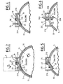
- FIGS 2 to 6 show an example of a system shutter 10, which conforms to this invention and which is intended to replace each shutter mobile 15 of Figure 1.
- This closure system comprises a tilting hatch 20, housed in a neck 21, projecting towards the exterior of the combustion chamber 5 and surrounding said orifice 10, at the base of a windsock 7.
- the projecting collar 21 thus comprises two longitudinal walls 21A and 21B and two transverse walls 21C and 21D. Moreover, inside said neck 21 is provided an intermediate wall 21E, parallel to the transverse walls 21C and 21D.
- the shaft 22 is eccentric with respect to each of said hatch parts 20A and 20B so that, with respect to said tree, these each have a large wing 23 and a small wing 24.
- each part of hatch 20A or 20B at least one through channel 25 is provided, setting gas communication the two sides of each of said hatch parts 20A and 20B.
- said hatch parts 20A and 20B can take either a position for closing the orifice 10 (see the figures 2 to 4), i.e. an open position of the latter (see figure 6).
- the hatch parts 20A and 20B rotate counterclockwise to switch from the shutter position to the position opening.
- the shaft 22 is engaged rotation with a cylindrical torsion bar 28, coaxial said shaft 22 and supported in a bearing 29, carried by the outer wall 30 of the combustion chamber 5.
- the end 31 of the torsion bar 28 has sections for be able to be gripped by pliers or the like.
- the hatch parts 20A, 20B being brought in and held in the closed position, for example manually, (see Figures 2 and 3), we can act on the end 31 to give the torsion bar 28 a constraint of predetermined twist in the direction of opening of said hatch parts and block said bar in this bandaged state, for example using a screw or a pin 32, taking for example support on the bearing 29.
- a link 33 is provided which is arranged on the side of said hatch parts 20A, 20B opposite the chamber combustion 5, which is fixed to the channels 25 through them transversely and which passes over the intermediate wall 21E.
- a stuffing 34 for example made of silicone, is disposed under the hatch parts 20A and 20B.
- stuffing 34 makes it possible to adapt the geometry of said parts hatch 20A and 20B to the geometry of the auxiliary thruster 14 and serves as a support for part 13A of the protection thermal 13, lying directly above said parts of hatch.
- the tightness to gas from said hatch parts 20A and 20B - except at level through channels 25 which ensure communication between the combustion chamber 5 and the sleeves air 7-- is obtained by said stuffing 34 and by said thermal protection 13, 13A.
- Figure 6 shows the hatch 20 in the open position.
- the geometry of this hatch is designed to participate to the best in combustion efficiency in the chamber 5, giving flow through air orifice 10 a rotation effect conducive to good mixing air / fuel.
Landscapes
- Engineering & Computer Science (AREA)
- Chemical & Material Sciences (AREA)
- Combustion & Propulsion (AREA)
- Mechanical Engineering (AREA)
- General Engineering & Computer Science (AREA)
- Toys (AREA)
- Nozzles (AREA)
- Fluidized-Bed Combustion And Resonant Combustion (AREA)
- Portable Nailing Machines And Staplers (AREA)
- Aiming, Guidance, Guns With A Light Source, Armor, Camouflage, And Targets (AREA)
- Iron Core Of Rotating Electric Machines (AREA)
Claims (11)
- Verschlusssystem für eine Öffnung (10) zum Einlassen von Verbrennungsluft in die Brennkammer (5) eines Staustrahltriebwerks (2), wobei das genannte Staustrahltriebwerk in einer Anfangsfunktionsphase, die dem Hochfahren des genannten Staustrahltriebwerks entspricht, dank einem sich aufbrauchenden Hilfstriebwerk (14), das in der genannten Brennkammer (5) angeordnet ist, als Rakete funktionieren kann, dann, wenn das genannte Staustrahltriebwerk eine vorbestimmte Geschwindigkeit erreicht, als eigentliches Staustrahltriebwerk mit Einspritzung von Brennstoff und Verbrennungsluft in die genannte Brennkammer (5) funktionieren kann, wobei das genannte Verschlusssystem mindestens eine in Bezug auf die genannte Brennkammer beweglich montierte Klappe (20A, 20B) umfasst, damit es entweder eine Verschlussstellung einnehmen kann, damit die genannte Klappe die genannte Öffnung (10) während der genannten Anfangsfunktionsphase als Rakete verschließt, oder eine Öffnungsstellung, in der die genannte Klappe die genannte Öffnung (10) für den Betrieb als Staustrahltriebwerk öffnet, dadurch gekennzeichnet, dass es Folgendes umfasst:ein elastisches System (28, 29, 31, 32), das die genannte Brennkammer und die genannte Klappe (20A, 20B) verbindet und entweder einen gespannten Zustand annimmt, der der genannten Verschlussstellung der genannten Klappe entspricht und in dem es darauf gerichtet ist, letztere zu öffnen, oder einen entspannten Zustand, in dem sich die genannte Klappe in der genannten Öffnungsstellung befindet; undein Rückhalteelement (33), um das genannte elastische System während der genannten Anfangsfunktionsphase als Rakete im genannten gespannten Zustand zu halten, wobei das genannte Rückhalteelement empfindlich gegenüber den vom genannten sich aufbrauchenden Hilfstriebwerk (14) ausgestoßenen Gasen ist, sodass das genannte Rückhalteelement (33) am Ende der Verbrennung des letzteren das genannte elastische System freigibt, das spontan von seinem gespannten Zustand in seinen entspannten Zustand wechselt und dabei die genannte Klappe aus ihrer Verschlussstellung in ihre Öffnungsstellung bringt.
- Verschlusssystem gemäß Anspruch 1,
dadurch gekennzeichnet, dass die genannte Klappe (20A, 20B) kippbar und rotationsfest mit einer drehbar an der genannten Brennkammer (5) montierten Achse (22) verbunden ist. - Verschlusssystem gemäß Anspruch 2,
dadurch gekennzeichnet, dass das genannte elastische System eine Drehstabfeder (28) umfasst, die sich in Eingriff mit der genannten drehbare Achse (22) der Klappe befindet. - Verschlusssystem gemäß Anspruch 2 oder 3,
dadurch gekennzeichnet, dass die genannte drehbare Achse (22) exzentrisch zur genannten Kippklappe (20A, 20B) angeordnet ist, und dass die vom genannten Hilfstriebwerk (14) erzeugten Gase auf die genannte Klappe eine Wirkung ausüben, die darauf gerichtet ist, diese in ihre Verschlussstellung zu drücken. - Verschlusssystem gemäß einem der Ansprüche 2 bis 4,
dadurch gekennzeichnet, dass die genannte Kippklappe (20A, 20B) und die genannte drehbare Achse (22) in einem Bund (21) angeordnet sind, der die Lufteinleitungsöffnung (10) umgibt und von der genannten Brennkammer (5) gesehen nach außen hin vorspringt. - Verschlusssystem gemäß einem der Ansprüche 3 bis 5,
dadurch gekennzeichnet, dass die genannte Drehachse (22) und die genannte Drehstabfeder (28) parallel zur Achse X-X der genannten Brennkammer (5) angeordnet sind. - Verschlusssystem gemäß einem beliebigen der Ansprüche 1 bis 6,
dadurch gekennzeichnet, dass das genannte Rückhalteteil (33) auf der Seite der genannten Klappe (20A, 20B), die der Brennkammer (5) gegenüber liegt, angeordnet ist, und dadurch, dass mindestens ein Kanal (25) vollständig durch die genannte Klappe hindurchführt, um das genannte Rückhalteteil (33) der Wirkung der vom genannten Hilfstriebwerk (14) erzeugten Gase auszusetzen. - Verschlusssystem gemäß einem beliebigen der Ansprüche 1 bis 7,
dadurch gekennzeichnet, dass das genannte Rückhalteelement ein Verbindungsteil (33) ist, das unter Einwirkung der vom genannten Hilfstriebwerk (14) erzeugten Gase zerstört werden kann. - Staustrahltriebwerk (2), das eine Brennkammer (5), die mit mindestens einer Öffnung (10) zum Einleiten von Verbrennungsluft in das Innere der genannten Brennkammer versehen ist, und ein System zum Verschließen der genannten Öffnung zum Einleiten von Verbrennungsluft umfasst, wobei das genannte Staustrahltriebwerk in einer Anfangsfunktionsphase, die dem Hochfahren des genannten Staustrahltriebwerks entspricht, dank einem sich aufbrauchenden Hilfstriebwerk (14), das in der genannten Brennkammer (5) angeordnet ist, als Rakete funktionieren kann, dann, wenn das genannte Staustrahltriebwerk eine vorbestimmte Geschwindigkeit erreicht, als eigentliches Staustrahltriebwerk mit Einspritzung von Brennstoff und Verbrennungsluft in die genannte Brennkammer funktionieren kann, wobei das genannte Verschlusssystem mindestens eine in Bezug auf die genannte Brennkammer (5) beweglich montierte Klappe (20A, 20B) umfasst, damit es entweder eine Verschlussstellung einnehmen kann, in der die genannte Klappe die genannte Öffnung (10) während der genannten Anfangsfunktionsphase als Rakete verschließt, oder eine Öffnungsstellung, in der die genannte Klappe die genannte Öffnung für den Betrieb als Staustrahltriebwerk öffnet, dadurch gekennzeichnet, dass das genannte Verschlusssystem Folgendes umfasst:ein elastisches System (28, 29, 31, 32), das die genannte Brennkammer und die genannte Klappe (20A, 20B) verbindet und entweder einen gespannten Zustand annimmt, der der genannten Verschlussstellung der genannten Klappe entspricht und in dem es darauf gerichtet ist, letztere zu öffnen, oder einen entspannten Zustand, in dem sich die genannte Klappe in der genannten Öffnungsstellung befindet; undein Rückhalteelement (33), um das genannte elastische System während der genannten Anfangsfunktionsphase als Rakete im genannten gespannten Zustand zu halten, wobei das genannte Rückhalteelement empfindlich gegenüber den vom genannten sich aufbrauchenden Hilfstriebwerk ausgestoßenen Gasen ist, sodass das genannte Rückhalteelement am Ende der Verbrennung des letzteren das genannte elastische System freigibt, das spontan von seinem gespannten Zustand in seinen entspannten Zustand wechselt und dabei die genannte Klappe aus ihrer Verschlussstellung in ihre Öffnungsstellung bringt.
- Staustrahltriebwerk gemäß Anspruch 9,
dadurch gekennzeichnet, dass das genannte Verschlusssystem die Besonderheiten eines der Ansprüche 2 bis 8 umfasst. - Flugkörper,
dadurch gekennzeichnet, dass er ein Staustrahltriebwerk gemäß Anspruch 9 oder 10 umfasst.
Applications Claiming Priority (2)
| Application Number | Priority Date | Filing Date | Title |
|---|---|---|---|
| FR9613237 | 1996-10-30 | ||
| FR9613237A FR2755182B1 (fr) | 1996-10-30 | 1996-10-30 | Systeme d'obturation pour un orifice d'entree d'air dans la chambre de combustion d'un statoreacteur |
Publications (2)
| Publication Number | Publication Date |
|---|---|
| EP0839999A1 EP0839999A1 (de) | 1998-05-06 |
| EP0839999B1 true EP0839999B1 (de) | 2002-09-25 |
Family
ID=9497171
Family Applications (1)
| Application Number | Title | Priority Date | Filing Date |
|---|---|---|---|
| EP97402549A Expired - Lifetime EP0839999B1 (de) | 1996-10-30 | 1997-10-28 | Einrichtung zur Beseitigung des Verschlusses der in die Brennkammer von Staustrahltriebwerken einmündenden Lufteinlaufkanäle |
Country Status (8)
| Country | Link |
|---|---|
| US (1) | US6116019A (de) |
| EP (1) | EP0839999B1 (de) |
| JP (1) | JP3996200B2 (de) |
| CA (1) | CA2220892C (de) |
| DE (1) | DE69715770T2 (de) |
| ES (1) | ES2180908T3 (de) |
| FR (1) | FR2755182B1 (de) |
| WO (1) | WO1998019063A1 (de) |
Families Citing this family (11)
| Publication number | Priority date | Publication date | Assignee | Title |
|---|---|---|---|---|
| FR2755182B1 (fr) * | 1996-10-30 | 1998-12-31 | Aerospatiale | Systeme d'obturation pour un orifice d'entree d'air dans la chambre de combustion d'un statoreacteur |
| FR2813344B1 (fr) * | 2000-08-28 | 2002-11-29 | Aerospatiale Matra Missiles | Systeme d'obturation pour un orifice d'un conduit, en particulier pour un orifice d'une voie d'introduction d'air dans la chambre de combustion d'un statoreacteur |
| FR2819556B1 (fr) * | 2001-01-12 | 2003-04-04 | Aerospatiale Matra Missiles | Systeme d'obturation pour un orifice d'un conduit, en particulier pour un orifice d'une voie d'introduction d'air dans la chambre de combustion d'un statoreacteur |
| FR2824106B1 (fr) | 2001-04-30 | 2003-08-29 | Aerospatiale Matra Missiles | Manche a air et engin volant, en particulier un missile, muni d'une telle manche a air |
| FR2840029B1 (fr) * | 2002-05-27 | 2004-08-13 | Mbdam | Systeme d'obturation pour un orifice d'un conduit, en particulier pour un orifice d'une voie d'introduction d'air dans la chambre de combustion d'un statoreacteur |
| RU2527800C1 (ru) * | 2013-05-23 | 2014-09-10 | Открытое Акционерное Общество "Государственное Машиностроительное Конструкторское Бюро "Радуга" Имени А.Я. Березняка" | Воздухозаборное устройство с заглушкой воздушно-реактивного двигателя |
| RU2555069C1 (ru) * | 2014-03-20 | 2015-07-10 | Открытое Акционерное Общество "Государственное Машиностроительное Конструкторское Бюро "Радуга" Имени А.Я. Березняка" | Пиротолкатель заглушки воздухозаборного устройства воздушно-реактивного устройства |
| RU171406U1 (ru) * | 2016-10-27 | 2017-05-30 | Российская Федерация, от имени которой выступает Министерство промышленности и торговли Российской Федерации (Минпромторг России) | Заглушка воздухозаборного устройства ракетно-прямоточного двигателя |
| RU181164U1 (ru) * | 2017-07-31 | 2018-07-05 | Российская Федерация, от имени которой выступает Министерство промышленности и торговли Российской Федерации (Минпромторг России) | Заглушка воздухозаборного устройства ракетно-прямоточного двигателя |
| RU182771U1 (ru) * | 2017-08-14 | 2018-08-31 | Российская Федерация, от имени которой выступает Министерство промышленности и торговли Российской Федерации (Минпромторг России) | Заглушка входа воздухозаборного устройства ракетно-прямоточного двигателя |
| RU180227U1 (ru) * | 2017-11-02 | 2018-06-06 | Закрытое акционерное общество "Институт телекоммуникаций" | Комбинированный трехрежимный реактивный двигатель |
Family Cites Families (15)
| Publication number | Priority date | Publication date | Assignee | Title |
|---|---|---|---|---|
| US3115008A (en) * | 1959-02-03 | 1963-12-24 | Cohen William | Integral rocket ramjet missile propulsion system |
| BE790265A (fr) * | 1971-10-20 | 1973-02-15 | Trox Gmbh Geb | Clapet de protection contre l'incendie |
| US4028886A (en) * | 1975-10-23 | 1977-06-14 | Mcdonnell Douglas Corporation | Passive chamber wall fragmenter |
| FR2402773A1 (fr) * | 1977-09-07 | 1979-04-06 | Europ Propulsion | Chambre de combustion de stato-fusee a booster integre |
| FR2627808A1 (fr) * | 1978-05-17 | 1989-09-01 | Onera (Off Nat Aerospatiale) | Perfectionnements apportes aux ensembles propulseurs a statoreacteurs et a leurs procedes de mise en oeuvre |
| DE3002977C2 (de) * | 1980-01-29 | 1982-11-11 | Messerschmitt-Bölkow-Blohm GmbH, 8000 München | Deckel aus leicht zerstörbarem Material zum Verschließen der in die Brennkammer von Staustrahl-Raketentriebwerken einmündenden Lufteinlauföffnungen, mit pyrotechnisch funktionierender Schlagvorrichtung zum Zerstören des Deckels |
| DE3003004C2 (de) * | 1980-01-29 | 1982-06-03 | Messerschmitt-Bölkow-Blohm GmbH, 8000 München | Deckel aus leicht zerstörbarem Material zum Verschließen der in die Brennkammer von kombinierten Staustrahl-Raketentriebwerken einmündenden Lufteinlauföffnungen, und Schlagvorrichtung zum Zerstören des Deckels |
| DE3242585C2 (de) * | 1982-11-18 | 1985-01-10 | Messerschmitt-Bölkow-Blohm GmbH, 8000 München | Verschlußeinrichtung für einen in die Brennkammer von Staustrahl-Raketentriebwerken einmündenden Lufteinlaufkanal |
| FR2661454B1 (fr) * | 1985-07-12 | 1994-02-11 | Onera | Perfectionnements apportes aux propulseurs de type statoreacteur. |
| JPH079216B2 (ja) * | 1989-07-24 | 1995-02-01 | 防衛庁技術研究本部長 | ラムロケット |
| JP2707821B2 (ja) * | 1990-10-05 | 1998-02-04 | 日産自動車株式会社 | ラムロケット |
| JP2800395B2 (ja) * | 1990-10-05 | 1998-09-21 | 日産自動車株式会社 | ラムロケット |
| JPH04148051A (ja) * | 1990-10-08 | 1992-05-21 | Nissan Motor Co Ltd | ラムロケット |
| JP3044576B2 (ja) * | 1991-02-12 | 2000-05-22 | 防衛庁技術研究本部長 | ラムロケット |
| FR2755182B1 (fr) * | 1996-10-30 | 1998-12-31 | Aerospatiale | Systeme d'obturation pour un orifice d'entree d'air dans la chambre de combustion d'un statoreacteur |
-
1996
- 1996-10-30 FR FR9613237A patent/FR2755182B1/fr not_active Expired - Lifetime
-
1997
- 1997-10-28 ES ES97402549T patent/ES2180908T3/es not_active Expired - Lifetime
- 1997-10-28 CA CA002220892A patent/CA2220892C/fr not_active Expired - Lifetime
- 1997-10-28 US US09/077,873 patent/US6116019A/en not_active Expired - Fee Related
- 1997-10-28 WO PCT/FR1997/001927 patent/WO1998019063A1/fr not_active Ceased
- 1997-10-28 EP EP97402549A patent/EP0839999B1/de not_active Expired - Lifetime
- 1997-10-28 DE DE69715770T patent/DE69715770T2/de not_active Expired - Lifetime
- 1997-10-28 JP JP52012498A patent/JP3996200B2/ja not_active Expired - Lifetime
Also Published As
| Publication number | Publication date |
|---|---|
| FR2755182B1 (fr) | 1998-12-31 |
| CA2220892A1 (fr) | 1998-04-30 |
| DE69715770D1 (de) | 2002-10-31 |
| DE69715770T2 (de) | 2003-05-08 |
| WO1998019063A1 (fr) | 1998-05-07 |
| FR2755182A1 (fr) | 1998-04-30 |
| JP3996200B2 (ja) | 2007-10-24 |
| US6116019A (en) | 2000-09-12 |
| EP0839999A1 (de) | 1998-05-06 |
| ES2180908T3 (es) | 2003-02-16 |
| JP2000503365A (ja) | 2000-03-21 |
| CA2220892C (fr) | 2007-01-16 |
Similar Documents
| Publication | Publication Date | Title |
|---|---|---|
| EP0839999B1 (de) | Einrichtung zur Beseitigung des Verschlusses der in die Brennkammer von Staustrahltriebwerken einmündenden Lufteinlaufkanäle | |
| EP0956441B1 (de) | Entfaltbare schubdüse | |
| EP0389358B1 (de) | Leitwerkausspreizungssystem für ein Geschoss | |
| EP1367251B1 (de) | Verschlusssystem für eine Öffnung einer Lufteinlassleitung einer Brennkammer eines Staustrahltriebwerks, sowie Staustrahltriebwerk und Flugkörper mit einem solchen System | |
| FR2561743A1 (fr) | Vanne pyrotechnique | |
| FR2490333A1 (fr) | Cartouche a actionnement pyrotechnique de charge utile avec securite | |
| CA2154110C (fr) | Dispositif pyrotechnique de lancement d'au moins un projectile | |
| FR2482665A1 (fr) | Moteur-fusee a carburant solide et a poussee variable | |
| EP1184559B1 (de) | Verschlusssystem für einen Leitungseinlass, sowie Staustrahltriebwerk und Rakete mit einem solchen System | |
| WO2023166389A1 (fr) | Dispositif de lancement pneumatique d'un drone | |
| EP1225326B1 (de) | Rohrverschlussvorrichtung, insbesondere für Luftrohre in einem Staustrahlantrieb | |
| BE861606A (fr) | Projectile de lancement de leurres electromagnetiques. | |
| FR2858662A1 (fr) | Appareil de combustion a propergol solide | |
| FR2530332A1 (fr) | Dispositif d'ouverture de l'empennage d'un projectile | |
| FR2584456A1 (fr) | Dispositif de fermeture temporaire d'un orifice interne d'un propulseur | |
| FR2930817A1 (fr) | Systeme d'obturation d'un conduit d'evacuation des gaz d'un lanceur de missiles | |
| EP0131079A1 (de) | Schubumkehrvorrichtung mit Klappe speziell für Flugzeugstrahltriebwerke | |
| EP4345009B1 (de) | Antriebseinheit für ein flugzeug | |
| EP0481851B1 (de) | Schliess- und Schutzvorrichtung für ein Gasauslasssystem eines senkrechten Abschussmoduls | |
| BE824041A (fr) | Cartouche pour la dispersion de leurres electromagnetiques. | |
| EP4538515A1 (de) | Antriebseinheit für ein flugzeug mit einem wärmeaustauschsystem in der abgasdüse | |
| FR2897114A1 (fr) | Dispositif d'allumage differe pour bloc de propergol a canal temporairement obture et bloc de propergol equipe d un tel dispositif. | |
| FR3151299A1 (fr) | Ensemble propulsif pour aéronef | |
| FR2699601A1 (fr) | Système de tuyère pour un propulseur à charge combustible et propulseur comportant au moins un tel système. | |
| BE883916A (fr) | Grenade a fusil explosive |
Legal Events
| Date | Code | Title | Description |
|---|---|---|---|
| PUAI | Public reference made under article 153(3) epc to a published international application that has entered the european phase |
Free format text: ORIGINAL CODE: 0009012 |
|
| AK | Designated contracting states |
Kind code of ref document: A1 Designated state(s): BE DE ES GB IT NL SE |
|
| AX | Request for extension of the european patent |
Free format text: AL;LT;LV;RO;SI |
|
| 17P | Request for examination filed |
Effective date: 19980526 |
|
| AKX | Designation fees paid |
Free format text: BE DE ES GB IT NL SE |
|
| RBV | Designated contracting states (corrected) |
Designated state(s): BE DE ES GB IT NL SE |
|
| RAP1 | Party data changed (applicant data changed or rights of an application transferred) |
Owner name: AEROSPATIALE MATRA |
|
| 17Q | First examination report despatched |
Effective date: 20010312 |
|
| GRAG | Despatch of communication of intention to grant |
Free format text: ORIGINAL CODE: EPIDOS AGRA |
|
| GRAG | Despatch of communication of intention to grant |
Free format text: ORIGINAL CODE: EPIDOS AGRA |
|
| GRAH | Despatch of communication of intention to grant a patent |
Free format text: ORIGINAL CODE: EPIDOS IGRA |
|
| GRAH | Despatch of communication of intention to grant a patent |
Free format text: ORIGINAL CODE: EPIDOS IGRA |
|
| GRAA | (expected) grant |
Free format text: ORIGINAL CODE: 0009210 |
|
| AK | Designated contracting states |
Kind code of ref document: B1 Designated state(s): BE DE ES GB IT NL SE |
|
| REG | Reference to a national code |
Ref country code: GB Ref legal event code: FG4D Free format text: NOT ENGLISH |
|
| GBT | Gb: translation of ep patent filed (gb section 77(6)(a)/1977) |
Effective date: 20020925 |
|
| REF | Corresponds to: |
Ref document number: 69715770 Country of ref document: DE Date of ref document: 20021031 |
|
| REG | Reference to a national code |
Ref country code: ES Ref legal event code: FG2A Ref document number: 2180908 Country of ref document: ES Kind code of ref document: T3 |
|
| PLBE | No opposition filed within time limit |
Free format text: ORIGINAL CODE: 0009261 |
|
| STAA | Information on the status of an ep patent application or granted ep patent |
Free format text: STATUS: NO OPPOSITION FILED WITHIN TIME LIMIT |
|
| 26N | No opposition filed |
Effective date: 20030626 |
|
| PGFP | Annual fee paid to national office [announced via postgrant information from national office to epo] |
Ref country code: NL Payment date: 20160913 Year of fee payment: 20 |
|
| PGFP | Annual fee paid to national office [announced via postgrant information from national office to epo] |
Ref country code: DE Payment date: 20161013 Year of fee payment: 20 Ref country code: GB Payment date: 20161014 Year of fee payment: 20 |
|
| PGFP | Annual fee paid to national office [announced via postgrant information from national office to epo] |
Ref country code: IT Payment date: 20161011 Year of fee payment: 20 Ref country code: BE Payment date: 20161027 Year of fee payment: 20 Ref country code: SE Payment date: 20161012 Year of fee payment: 20 Ref country code: ES Payment date: 20161027 Year of fee payment: 20 |
|
| REG | Reference to a national code |
Ref country code: DE Ref legal event code: R071 Ref document number: 69715770 Country of ref document: DE |
|
| REG | Reference to a national code |
Ref country code: NL Ref legal event code: MK Effective date: 20171027 |
|
| REG | Reference to a national code |
Ref country code: GB Ref legal event code: PE20 Expiry date: 20171027 |
|
| REG | Reference to a national code |
Ref country code: BE Ref legal event code: MK Effective date: 20171028 |
|
| PG25 | Lapsed in a contracting state [announced via postgrant information from national office to epo] |
Ref country code: GB Free format text: LAPSE BECAUSE OF EXPIRATION OF PROTECTION Effective date: 20171027 |
|
| REG | Reference to a national code |
Ref country code: ES Ref legal event code: FD2A Effective date: 20180508 |
|
| PG25 | Lapsed in a contracting state [announced via postgrant information from national office to epo] |
Ref country code: ES Free format text: LAPSE BECAUSE OF EXPIRATION OF PROTECTION Effective date: 20171029 |