EP0839749A1 - Procédé et installation pour enrouler et dérouler un câble métallique - Google Patents
Procédé et installation pour enrouler et dérouler un câble métallique Download PDFInfo
- Publication number
- EP0839749A1 EP0839749A1 EP97490030A EP97490030A EP0839749A1 EP 0839749 A1 EP0839749 A1 EP 0839749A1 EP 97490030 A EP97490030 A EP 97490030A EP 97490030 A EP97490030 A EP 97490030A EP 0839749 A1 EP0839749 A1 EP 0839749A1
- Authority
- EP
- European Patent Office
- Prior art keywords
- hub
- cable
- unwinding
- circle
- support
- Prior art date
- Legal status (The legal status is an assumption and is not a legal conclusion. Google has not performed a legal analysis and makes no representation as to the accuracy of the status listed.)
- Withdrawn
Links
Images

Classifications
-
- B—PERFORMING OPERATIONS; TRANSPORTING
- B65—CONVEYING; PACKING; STORING; HANDLING THIN OR FILAMENTARY MATERIAL
- B65H—HANDLING THIN OR FILAMENTARY MATERIAL, e.g. SHEETS, WEBS, CABLES
- B65H75/00—Storing webs, tapes, or filamentary material, e.g. on reels
- B65H75/02—Cores, formers, supports, or holders for coiled, wound, or folded material, e.g. reels, spindles, bobbins, cop tubes, cans, mandrels or chucks
- B65H75/34—Cores, formers, supports, or holders for coiled, wound, or folded material, e.g. reels, spindles, bobbins, cop tubes, cans, mandrels or chucks specially adapted or mounted for storing and repeatedly paying-out and re-storing lengths of material provided for particular purposes, e.g. anchored hoses, power cables
- B65H75/36—Cores, formers, supports, or holders for coiled, wound, or folded material, e.g. reels, spindles, bobbins, cop tubes, cans, mandrels or chucks specially adapted or mounted for storing and repeatedly paying-out and re-storing lengths of material provided for particular purposes, e.g. anchored hoses, power cables without essentially involving the use of a core or former internal to a stored package of material, e.g. with stored material housed within casing or container, or intermittently engaging a plurality of supports as in sinuous or serpentine fashion
- B65H75/362—Cores, formers, supports, or holders for coiled, wound, or folded material, e.g. reels, spindles, bobbins, cop tubes, cans, mandrels or chucks specially adapted or mounted for storing and repeatedly paying-out and re-storing lengths of material provided for particular purposes, e.g. anchored hoses, power cables without essentially involving the use of a core or former internal to a stored package of material, e.g. with stored material housed within casing or container, or intermittently engaging a plurality of supports as in sinuous or serpentine fashion with stored material housed within a casing or container
- B65H75/364—Cores, formers, supports, or holders for coiled, wound, or folded material, e.g. reels, spindles, bobbins, cop tubes, cans, mandrels or chucks specially adapted or mounted for storing and repeatedly paying-out and re-storing lengths of material provided for particular purposes, e.g. anchored hoses, power cables without essentially involving the use of a core or former internal to a stored package of material, e.g. with stored material housed within casing or container, or intermittently engaging a plurality of supports as in sinuous or serpentine fashion with stored material housed within a casing or container the stored material being coiled
-
- B—PERFORMING OPERATIONS; TRANSPORTING
- B65—CONVEYING; PACKING; STORING; HANDLING THIN OR FILAMENTARY MATERIAL
- B65H—HANDLING THIN OR FILAMENTARY MATERIAL, e.g. SHEETS, WEBS, CABLES
- B65H75/00—Storing webs, tapes, or filamentary material, e.g. on reels
- B65H75/02—Cores, formers, supports, or holders for coiled, wound, or folded material, e.g. reels, spindles, bobbins, cop tubes, cans, mandrels or chucks
- B65H75/18—Constructional details
- B65H75/20—Skeleton construction, e.g. formed of wire
Definitions
- the present invention relates to the winding and unwinding of a wire rope from a reel-type device.
- a drum which has the shape of a wheel comprising a central hub, radial spokes starting from the hub and having curved extensions which together form the rim of the wheel and define a housing substantially toroidal for the wire rope.
- This drum has also a circle passing through the free ends of the extensions, said circle delimiting the cable introduction and extraction zone.
- the axis of the hub of the reel is secured by one of its ends to a horizontal rod supported by a frame, said rod being able to pivot in two positions, a first position in which the hub is horizontal and a second position in which the hub is vertical with the circle for insertion and extraction of the cable directed upwards.
- An arm terminated by a cable passage eyelet is attached to the end of the hub opposite the horizontal rod.
- this known device does not make it possible to obtain reliably an optimal unwinding of a wire rope in the since during the course of the event, the formation of loops, due to a circumferential speed of the drum different from the actual unwinding of the cable.
- loop a turn which was in the toroidal housing of the drum and which escapes from it in this same configuration.
- it is essential to remedy it manually if not of the tensioning of the cable by any mechanical means, the cable will be chewable and unusable.
- the goal set by the applicant is to propose a process simple to implement a device of the drum type, for the winding and unwinding of a metallic cable which overcomes the aforementioned drawback, said reel having the shape of a wheel with a central hub, with a radial element or a plurality of radial spokes starting from the hub and having one or more curved extensions, the or the extensions forming the rim of the wheel and delimiting a substantially toroidal housing for the wire rope and with a circle passing through the free end (s) of said extension (s).
- the method consists, to unwind the cable, place the hub on a vertical axis mounted on a support, with the circle facing downwards at a short distance from said support, to pull the cable substantially horizontally and to unwind by letting it touch the vertical axis and the support. Traction on the cable at the start of unwinding leads it to touch the vertical axis, between the support and the hub. As soon as the reel rotation is synchronous with the unwinding of the cable, the cable no longer touches the axis. Finally, due to the contact between the portion of cable coming out of the drum and the support, braking is obtained which regulates the course. So usual the cable unwinding is done outdoors and the support on which is mounted the vertical axis is none other than the ground.
- It is another object of the invention to propose a installation for winding and unwinding a wire rope which comprises a drum in the form of a wheel with a central hub, with a radial member or a plurality of radial radii extending from the hub and having one or more curved extensions so that the or said extensions, forming the rim of the wheel, delimit a substantially toroidal housing for said metal cable and with a circle passing through the free end (s) of said one (s) extensions.
- the installation also includes a vertical axis of reduced height, mounted on a support; moreover the reel hub is able to be mounted on the axis vertical in a first position in which the circle is turned towards the top for winding the cable and a second position in which the circle is turned down for the unwinding of the cable.
- the vertical axis has a height such that the distance between the support and the equatorial plane of the toroidal housing is approximately twenty centimeters.
- the hub has a length which is less than or equal to half the diameter of the torus formed by the one or more curved extensions, said hub being disposed substantially symmetrically with respect to the equatorial plane of said torus.
- the hub has a length of the order of 50 millimeters.
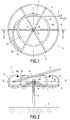
- Installation 1 for winding and unwinding the cable metal 2 comprises a reel 3 and a vertical axis 4 mounted on a support 5.
- the reel 3 consists of a central hub 6, of six radial spokes 7, starting from the hub 6 and comprising curved extensions 8. These curved extensions 8 delimit, for the metal cable 2, a substantially toroidal housing 9.
- the free ends 8 has curved extensions 8 are fixed to a circle 10 which constitutes the zone of introduction and extraction of the cable 2, respectively during its winding and its unwinding.
- the reel 3 may also include a second circle 11, fixed externally to the curved extensions 8 to reinforce the mechanical strength of said reel 3.
- the vertical axis 4 is fixed to the support 5 by any means appropriate.
- the support 5 is partially a yoke concrete, in which a nut is embedded, the vertical axis 4 can have its threaded lower end so that it can be screwed into the nut in question.
- Axis 4 can also be anchored in the clevis itself of concrete permanently.
- the upper end 4 a of the vertical axis 4 has a diameter which is slightly less than the inside diameter of the hub 6, consisting of a simple cylindrical tube, so that said hub 6 can easily be fitted on this end 4 a .
- the locking in position of the hub 6 relative to the axis 4 must be obtained by a stop, which can for example be a pin 12 passing through the end 4 a , by a diametrical hole and on which the hub 6 rests during the positioning of the reel on the axis 4. It can also be a stop integrated in the axis 4, for example the axis 4 having, to form this stop, a diameter equal to or greater than the outside diameter of the hub 6, with the exception of the end 4 a as indicated above.
- the hub 6 has a length I which is significantly less than the diameter D of the O-ring housing 9; moreover, this hub 6 is arranged symmetrically relative to the equatorial plane GG 'of the toroidal housing 9.
- the reel 3 is placed on the vertical axis 4, the circle 10 being turned upwards. Introducing the first end 2a of the cable inside the housing ring 9 through the inner area 13 of the circle 10. Optionally this end 2a is locked in position by a system 14 in which it can be fitted or s 'clip on.
- the operator just needs to grab the cable, push in the direction of arrow F in Figure 1; the cable 2 is rigid enough to be pressed into the toroidal housing 9 on the largest diameter remaining available therein, the reel 3 rotating freely on the axis 4 due to the forces brought into play during the thrust of cable 2 by the operator. Without special precautions, the turns normally form inside the drum.
- the operator need only place the second end of the latter inside the toroidal housing, even when the said end has a hook.
- the operator places the reel 3 on the vertical axis 4 with the circle 10 facing the support 5. He grabs the second end of cable 2, takes it out of the O-ring housing 9 by passing it through the inner zone 13 of the circle 10 and simply pull this end moving from the length to unroll.
- the cable comes to bear on the vertical axis 4, below the hub 6 and this so that the unwinding speed of cable 2 is not synchronous with the speed of rotation of the reel 3 on its axis 4.
- the latter comes to bear on the support 5, which achieves braking allowing the self-regulation of the course.
- the braking effect is preferably obtained with a vertical axis having a reduced height with respect to the support so that the contact with the support can take place quickly after the extraction of the cable.
- the vertical axis will have a height such as the distance between the support 5 and the equatorial plane G-G 'of the toroidal housing 9 will be around 20cm.
- the reel had a diameter of about 430mm, the toroidal housing 9 a diameter of around 100mm and the hub a length of around 50mm.
- the reel had a diameter of the order of 540mm, the toroidal housing 9 a diameter of on the order of 120 to 130mm and the hub a length on the order of 50mm. It should be noted that variants allowing the winding and the cable unwinds of different lengths can use hubs of the same length, which makes it possible to standardize manufacturing. In these drums, it is possible to accommodate lengths from 20 to 30 meters of cable from 10 to 16mm in diameter. Course all above values are indicative and must be adapted to the diameter and the length of the cable.
- these are the extensions curved with six radial spokes which form the toroidal housing of the cable.
- the number of six is, according to the applicant, a sufficient number to that the cable cannot come out of its housing.
Landscapes
- Storage Of Web-Like Or Filamentary Materials (AREA)
Abstract
Description
- La figure 1 est une vue en plan de dessus de l'installation en début d'enroulement,
- La figure 2 est une vue en coupe de l'installation de la figure 1 selon l'axe II-II ,
- La figure 3 est une vue schématique en coupe de l'installation en cours de déroulement.
Claims (6)
- Procédé de mise en oeuvre d'un dispositif du type touret (3), pour l'enroulement et le déroulement d'un câble métallique (2), ledit touret (3) ayant la forme d'une roue avec un moyeu central (6) , avec un élément radial ou une pluralité de rayons radiaux (7) partant du moyeu (6) et présentant un (ou des) prolongements recourbés, (8) le (ou lesdits) prolongement(s) formant la jante de la roue et délimitant un logement sensiblement torique (9) pour ledit câble métallique (2) et avec un cercle (10) passant par la (ou les) extrémité(s) libre(s) (8a) du (ou desdits) prolongement(s) (8), ledit procédé étant caractérisé en ce qu'il consiste, pour le déroulement du câble, à placer le moyeu (6) sur un axe vertical (4) monté sur un support (5), avec le cercle (10) tourné vers le bas à faible distance dudit support (5), à tirer le câble (2) sensiblement horizontalement et à le dévider en le laissant toucher l'axe vertical (4) et le support (5).
- Installation (1) d'enroulement et de déroulement d'un câble métallique (2) comprenant un touret (3) ayant la forme d'une roue avec un moyeu central (6), avec au moins un élément radial ou une pluralité de rayons radiaux (7) partant du moyeu (6) et présentant un (ou des) prolongement(s) recourbé(s) (8) en sorte que le (ou lesdits) prolongement(s) (8), formant la jante de la roue, délimite(nt) un logement sensiblement torique (9) pour ledit câble métallique (2) et avec un cercle (10) passant par la (ou les) extrémité(s) libre(s) (8a) du (ou desdits) prolongement(s) (8) , caractérisée en ce qu'elle comprend également un axe vertical (4) de hauteur réduite, monté sur un support (5) et en ce que le moyeu (6) du touret (3) est apte à être monté sur l'axe vertical (4) selon une première position dans laquelle le cercle (10) est tourné vers le haut pour l'enroulement du câble (2) et une seconde position dans laquelle le cercle (10) est tourné vers le bas pour le déroulement du câble (2).
- Installation selon la revendication 2 caractérisée en ce que l'axe vertical a une hauteur telle que la distance entre le support (5) et le plan équatorial (G-G') du logement torique (9) est d'environ 0,2m.
- Installation selon l'une des revendications 2 ou 3 caractérisée en ce que le moyeu (6) a une longueur (I) qui est inférieure ou égale à la moitié du diamètre (D) du logement torique (9) et en ce que ledit moyeu (6) est disposé sensiblement symétriquement par rapport au plan équatorial (G-G') dudit logement (9).
- Installation selon la revendication 4 caractérisée en ce que le moyeu (6) a une longueur (I) de l'ordre de 50mm.
- Installation selon l'une des revendications 2 à 5 caractérisée en ce que le moyeu (6) est un tube cylindrique apte à venir s'emmancher sur l'axe vertical (4) , en ce que l'axe vertical (4) comporte au moins un trou diamétral et en ce qu'elle comporte une goupille , apte à pénétrer dans ledit trou diamétral pour servir de butée au moyeu (6).
Applications Claiming Priority (2)
| Application Number | Priority Date | Filing Date | Title |
|---|---|---|---|
| FR9611341A FR2753187B1 (fr) | 1996-09-12 | 1996-09-12 | Touret pour cable metallique a enroulement inverse |
| FR9611341 | 1996-09-12 |
Publications (1)
| Publication Number | Publication Date |
|---|---|
| EP0839749A1 true EP0839749A1 (fr) | 1998-05-06 |
Family
ID=9495825
Family Applications (1)
| Application Number | Title | Priority Date | Filing Date |
|---|---|---|---|
| EP97490030A Withdrawn EP0839749A1 (fr) | 1996-09-12 | 1997-09-12 | Procédé et installation pour enrouler et dérouler un câble métallique |
Country Status (2)
| Country | Link |
|---|---|
| EP (1) | EP0839749A1 (fr) |
| FR (1) | FR2753187B1 (fr) |
Cited By (4)
| Publication number | Priority date | Publication date | Assignee | Title |
|---|---|---|---|---|
| EP0959035A2 (fr) * | 1998-05-18 | 1999-11-24 | Latchways plc | Dévidoir |
| GB2337508A (en) * | 1998-05-18 | 1999-11-24 | Latchways Plc | Rotatable cable coiler |
| NL1024623C2 (nl) * | 2003-10-26 | 2005-04-28 | Adrianus Cornelis J Swanenberg | Systeem voor het opbergen van kabels. |
| DE202016101234U1 (de) | 2015-03-06 | 2016-05-02 | Haslacher & Haslacher Immobilien & Patentverwaltungs Gmbh | Vorrichtung zum Auf- und Abwickeln von Strangmaterial |
Citations (4)
| Publication number | Priority date | Publication date | Assignee | Title |
|---|---|---|---|---|
| US2540434A (en) * | 1949-05-16 | 1951-02-06 | Theodore H Fengler | Hose reel |
| US3491967A (en) * | 1967-08-28 | 1970-01-27 | James L Sawyer | Mobile apparatus for dispensing coiled cable and the like |
| GB2184094A (en) * | 1985-11-07 | 1987-06-17 | Tampella Oy Ab | Wire store |
| DE3636943A1 (de) * | 1986-10-30 | 1988-05-11 | Katimex Cielker Gmbh | Einziehgeraet |
-
1996
- 1996-09-12 FR FR9611341A patent/FR2753187B1/fr not_active Expired - Fee Related
-
1997
- 1997-09-12 EP EP97490030A patent/EP0839749A1/fr not_active Withdrawn
Patent Citations (4)
| Publication number | Priority date | Publication date | Assignee | Title |
|---|---|---|---|---|
| US2540434A (en) * | 1949-05-16 | 1951-02-06 | Theodore H Fengler | Hose reel |
| US3491967A (en) * | 1967-08-28 | 1970-01-27 | James L Sawyer | Mobile apparatus for dispensing coiled cable and the like |
| GB2184094A (en) * | 1985-11-07 | 1987-06-17 | Tampella Oy Ab | Wire store |
| DE3636943A1 (de) * | 1986-10-30 | 1988-05-11 | Katimex Cielker Gmbh | Einziehgeraet |
Cited By (5)
| Publication number | Priority date | Publication date | Assignee | Title |
|---|---|---|---|---|
| EP0959035A2 (fr) * | 1998-05-18 | 1999-11-24 | Latchways plc | Dévidoir |
| GB2337508A (en) * | 1998-05-18 | 1999-11-24 | Latchways Plc | Rotatable cable coiler |
| EP0959035A3 (fr) * | 1998-05-18 | 2000-08-16 | Latchways plc | Dévidoir |
| NL1024623C2 (nl) * | 2003-10-26 | 2005-04-28 | Adrianus Cornelis J Swanenberg | Systeem voor het opbergen van kabels. |
| DE202016101234U1 (de) | 2015-03-06 | 2016-05-02 | Haslacher & Haslacher Immobilien & Patentverwaltungs Gmbh | Vorrichtung zum Auf- und Abwickeln von Strangmaterial |
Also Published As
| Publication number | Publication date |
|---|---|
| FR2753187B1 (fr) | 1998-12-04 |
| FR2753187A1 (fr) | 1998-03-13 |
Similar Documents
| Publication | Publication Date | Title |
|---|---|---|
| EP0554212B1 (fr) | Dispositif d'enroulement de cordon de suspension de store | |
| EP0034688A2 (fr) | Machine à corder les raquettes | |
| EP0009058B1 (fr) | Dispositif de suspension pour nacelle d'entretien des façades | |
| EP0126679B1 (fr) | Navire à au moins deux coques jumelées, comportant plusieurs mâts | |
| FR2610889A1 (fr) | Levier de commande de changement de vitesse pour une bicyclette | |
| EP0839749A1 (fr) | Procédé et installation pour enrouler et dérouler un câble métallique | |
| EP0064470A1 (fr) | Dispositif destiné à guider le déroulement du fil à partir d'une bobine disposée en dessous d'une autre dans le pot d'une broche à retordre | |
| EP0420721B1 (fr) | Procédé d'enroulement en double d'un câble ou analogue sur la surface externe d'un touret | |
| EP1932042B1 (fr) | Machine de pose de cable optique autour d'un cable porteur | |
| EP1983143B1 (fr) | Dispositif d'enroulement d'un cordon de suspension comprenant un moyen de guidage du cordon | |
| FR2743359A1 (fr) | Treuil pour un element flexible continu | |
| WO2005118388A1 (fr) | Dispositif pour emmagasiner et etarquer une voile d'avant pour voilier | |
| FR2764932A1 (fr) | Procede de montage de cables sur un tambour de leve-vitre de vehicule automobile et dispositif pour la mise en oeuvre de ce procede | |
| WO2001052961A1 (fr) | Barre de controle pour aile de traction avec enrouleur integre | |
| FR2464218A1 (fr) | Dispositif de recuperation d'un cable de manutention d'une charge immergee | |
| WO2007031506A2 (fr) | Machine de pose de cable optique automotrice | |
| EP0026024B1 (fr) | Porte-écheveau pour le défilage d'un écheveau de fil | |
| FR2700599A1 (fr) | Transporteur de câbles ou canalisations dans une tranchée ouverte. | |
| FR2587539A1 (fr) | Appareil pour enrouler un filament autour d'un gabarit | |
| CH369947A (fr) | Appareil pour l'emmagasinement et la restitution d'un câble ou analogue | |
| CH203850A (fr) | Enrouleur rattrape-trolley. | |
| FR2853840A1 (fr) | Procede et dispositif d'enroulage de lien souple de grande longueur | |
| WO2003018461A1 (fr) | Treuil motorise | |
| FR2878823A1 (fr) | Dispositif emmagasineur de voile d'avant pour voilier | |
| BE530046A (fr) |
Legal Events
| Date | Code | Title | Description |
|---|---|---|---|
| PUAI | Public reference made under article 153(3) epc to a published international application that has entered the european phase |
Free format text: ORIGINAL CODE: 0009012 |
|
| AK | Designated contracting states |
Kind code of ref document: A1 Designated state(s): CH DE ES FR GB LI NL |
|
| AX | Request for extension of the european patent |
Free format text: AL;LT;LV;RO;SI |
|
| 17P | Request for examination filed |
Effective date: 19981104 |
|
| AKX | Designation fees paid |
Free format text: CH DE ES FR GB LI NL |
|
| RBV | Designated contracting states (corrected) |
Designated state(s): CH DE ES FR GB LI NL |
|
| RAP1 | Party data changed (applicant data changed or rights of an application transferred) |
Owner name: TRACTEL S.A. |
|
| RIN1 | Information on inventor provided before grant (corrected) |
Inventor name: MANOUVRIEZ, JEAN |
|
| GRAG | Despatch of communication of intention to grant |
Free format text: ORIGINAL CODE: EPIDOS AGRA |
|
| GRAG | Despatch of communication of intention to grant |
Free format text: ORIGINAL CODE: EPIDOS AGRA |
|
| GRAH | Despatch of communication of intention to grant a patent |
Free format text: ORIGINAL CODE: EPIDOS IGRA |
|
| 17Q | First examination report despatched |
Effective date: 20010213 |
|
| STAA | Information on the status of an ep patent application or granted ep patent |
Free format text: STATUS: THE APPLICATION IS DEEMED TO BE WITHDRAWN |
|
| 18D | Application deemed to be withdrawn |
Effective date: 20010630 |