EP0839674B1 - Pneumatique à bourrelets conçus pour faciliter le démontage - Google Patents
Pneumatique à bourrelets conçus pour faciliter le démontage Download PDFInfo
- Publication number
- EP0839674B1 EP0839674B1 EP19970118228 EP97118228A EP0839674B1 EP 0839674 B1 EP0839674 B1 EP 0839674B1 EP 19970118228 EP19970118228 EP 19970118228 EP 97118228 A EP97118228 A EP 97118228A EP 0839674 B1 EP0839674 B1 EP 0839674B1
- Authority
- EP
- European Patent Office
- Prior art keywords
- bead
- wall
- tyre
- axially
- radially
- Prior art date
- Legal status (The legal status is an assumption and is not a legal conclusion. Google has not performed a legal analysis and makes no representation as to the accuracy of the status listed.)
- Expired - Lifetime
Links
- 239000011324 bead Substances 0.000 title claims description 76
- 229920001971 elastomer Polymers 0.000 claims description 18
- 239000012791 sliding layer Substances 0.000 claims description 18
- 150000001875 compounds Chemical class 0.000 claims description 14
- 239000005060 rubber Substances 0.000 claims description 11
- 239000000806 elastomer Substances 0.000 claims description 7
- 229920005549 butyl rubber Polymers 0.000 claims description 5
- 230000005012 migration Effects 0.000 claims description 4
- 238000013508 migration Methods 0.000 claims description 4
- OXDXXMDEEFOVHR-CLFAGFIQSA-N (z)-n-[2-[[(z)-octadec-9-enoyl]amino]ethyl]octadec-9-enamide Chemical compound CCCCCCCC\C=C/CCCCCCCC(=O)NCCNC(=O)CCCCCCC\C=C/CCCCCCCC OXDXXMDEEFOVHR-CLFAGFIQSA-N 0.000 claims description 3
- 244000043261 Hevea brasiliensis Species 0.000 claims description 2
- 239000005062 Polybutadiene Substances 0.000 claims description 2
- 239000002174 Styrene-butadiene Substances 0.000 claims description 2
- 125000000484 butyl group Chemical group [H]C([*])([H])C([H])([H])C([H])([H])C([H])([H])[H] 0.000 claims description 2
- 229920003052 natural elastomer Polymers 0.000 claims description 2
- 229920001194 natural rubber Polymers 0.000 claims description 2
- FATBGEAMYMYZAF-KTKRTIGZSA-N oleamide Chemical compound CCCCCCCC\C=C/CCCCCCCC(N)=O FATBGEAMYMYZAF-KTKRTIGZSA-N 0.000 claims description 2
- FATBGEAMYMYZAF-UHFFFAOYSA-N oleicacidamide-heptaglycolether Natural products CCCCCCCCC=CCCCCCCCC(N)=O FATBGEAMYMYZAF-UHFFFAOYSA-N 0.000 claims description 2
- 229920002857 polybutadiene Polymers 0.000 claims description 2
- 229920003048 styrene butadiene rubber Polymers 0.000 claims description 2
- 239000000463 material Substances 0.000 claims 3
- 235000014113 dietary fatty acids Nutrition 0.000 claims 1
- 229930195729 fatty acid Natural products 0.000 claims 1
- 239000000194 fatty acid Substances 0.000 claims 1
- 150000004665 fatty acids Chemical class 0.000 claims 1
- 239000000203 mixture Substances 0.000 description 11
- 239000010410 layer Substances 0.000 description 5
- 230000003014 reinforcing effect Effects 0.000 description 5
- 238000010586 diagram Methods 0.000 description 4
- 230000004323 axial length Effects 0.000 description 2
- -1 polytetrafluoroethylene Polymers 0.000 description 2
- 150000001408 amides Chemical class 0.000 description 1
- 238000004873 anchoring Methods 0.000 description 1
- 238000006073 displacement reaction Methods 0.000 description 1
- 238000009472 formulation Methods 0.000 description 1
- 230000004927 fusion Effects 0.000 description 1
- 229920001343 polytetrafluoroethylene Polymers 0.000 description 1
- 239000004810 polytetrafluoroethylene Substances 0.000 description 1
- 230000002787 reinforcement Effects 0.000 description 1
- 230000000717 retained effect Effects 0.000 description 1
- 238000004804 winding Methods 0.000 description 1
Images


Classifications
-
- B—PERFORMING OPERATIONS; TRANSPORTING
- B60—VEHICLES IN GENERAL
- B60C—VEHICLE TYRES; TYRE INFLATION; TYRE CHANGING; CONNECTING VALVES TO INFLATABLE ELASTIC BODIES IN GENERAL; DEVICES OR ARRANGEMENTS RELATED TO TYRES
- B60C15/00—Tyre beads, e.g. ply turn-up or overlap
- B60C15/0009—Tyre beads, e.g. ply turn-up or overlap features of the carcass terminal portion
- B60C15/0018—Tyre beads, e.g. ply turn-up or overlap features of the carcass terminal portion not folded around the bead core, e.g. floating or down ply
-
- B—PERFORMING OPERATIONS; TRANSPORTING
- B44—DECORATIVE ARTS
- B44D—PAINTING OR ARTISTIC DRAWING, NOT OTHERWISE PROVIDED FOR; PRESERVING PAINTINGS; SURFACE TREATMENT TO OBTAIN SPECIAL ARTISTIC SURFACE EFFECTS OR FINISHES
- B44D2/00—Special techniques in artistic painting or drawing, e.g. oil painting, water painting, pastel painting, relief painting
-
- B—PERFORMING OPERATIONS; TRANSPORTING
- B44—DECORATIVE ARTS
- B44D—PAINTING OR ARTISTIC DRAWING, NOT OTHERWISE PROVIDED FOR; PRESERVING PAINTINGS; SURFACE TREATMENT TO OBTAIN SPECIAL ARTISTIC SURFACE EFFECTS OR FINISHES
- B44D3/00—Accessories or implements for use in connection with painting or artistic drawing, not otherwise provided for; Methods or devices for colour determination, selection, or synthesis, e.g. use of colour tables
-
- B—PERFORMING OPERATIONS; TRANSPORTING
- B60—VEHICLES IN GENERAL
- B60C—VEHICLE TYRES; TYRE INFLATION; TYRE CHANGING; CONNECTING VALVES TO INFLATABLE ELASTIC BODIES IN GENERAL; DEVICES OR ARRANGEMENTS RELATED TO TYRES
- B60C15/00—Tyre beads, e.g. ply turn-up or overlap
- B60C15/02—Seating or securing beads on rims
- B60C15/024—Bead contour, e.g. lips, grooves, or ribs
-
- B—PERFORMING OPERATIONS; TRANSPORTING
- B60—VEHICLES IN GENERAL
- B60C—VEHICLE TYRES; TYRE INFLATION; TYRE CHANGING; CONNECTING VALVES TO INFLATABLE ELASTIC BODIES IN GENERAL; DEVICES OR ARRANGEMENTS RELATED TO TYRES
- B60C15/00—Tyre beads, e.g. ply turn-up or overlap
- B60C15/06—Flipper strips, fillers, or chafing strips and reinforcing layers for the construction of the bead
- B60C15/0603—Flipper strips, fillers, or chafing strips and reinforcing layers for the construction of the bead characterised by features of the bead filler or apex
Definitions
- the present invention relates to tires. More specifically, it relates to an improved design of their beads intended to facilitate their disassembly.
- Dismantling in particular involves applying a fairly significant effort to the bead at or just above the rim hook.
- This effort is oriented parallel to the axis of rotation and is usually applied by a push on successive portions of the circumference of the bead corresponding to arcs of a circle of about 60 degrees.
- This is the first phase of the disassembly whose purpose is to loosen the bead, that is to make it leave radially inner seat or wall away from the rim flange and bring it to the central hollow of the rim.
- the tire bead is subjected to relatively extended forces localized and very important.
- Document JP58-4608 presents a tire, the part of the beads of which intended to be in contact with the seat of a rim is coated with a layer porous polytetrafluoroethylene. The purpose of this layer is to facilitate the place the tire on the rim. The characteristics of the preamble to the claim 1 correspond to this state of the art.
- the subject of the invention is an improvement of the beads of a tire intended to facilitate its successive dismantling without damaging its beads and without sacrificing performance in use.
- a tire comprising a crown and extended sidewalls by beads defining an internal cavity, each bead being delimited, on the radially inner side, by a radially inner wall having a part axially outer and an axially inner part, said wall being substantially frustoconical and being intended to rest on a rim and, on the side of the internal cavity of the tire, by an axially inner wall, is characterized in that a sliding layer covers the axially inner part of the radially inner wall and at least the radially lowest part of the axially inner wall.
- the sliding layer covers only the axially inner part of the wall radially inner, that is to say the part of this wall disposed on the side of the internal cavity of the tire. This limitation is very important in order not to degrade the properties of use of the tire, in particular the anti-loosening efficiency "humps" and to avoid any rotation on the rim.
- the part of the axially inner wall covered by said sliding layer extends radially over a length of at least 10 mm.
- the bead When the tire is removed, the bead will, under the action of the tool disassembly (the pusher), start a tilting movement centered on the connection zone between the axially inner wall and the radially wall inside of the bead.
- the amplitude of this tilt depends on the rigidity in rotation of the bead. In the most common case, a rigid bead in rotation, tilting is very limited. This movement however induces a increased contact pressures in the area of the wall radially interior closest to the internal cavity of the tire, area comprising the sliding layer, and a decrease in clamping forces between the rest of the radially inner wall and rim.
- the forces transmitted by the pusher can cause a tilting complete and bring the axially inner wall of the bead into contact with the rim.
- the contact area between the bead and the rim again has a low coefficient of friction, which facilitates the loosening of the bead, crossing the hump and as before appreciably increases the value of the disconnected bead circle arc for a given value of the offset imposed by the pusher.
- the presence of the layer of slip reduces the elongations imposed on the rod wires during a disassembly, which limits their risk of damage.
- the function of the sliding layer is to provide a coefficient of friction low between the bead and the rim throughout the life of the tire.
- This layer may in particular consist of a rubber tongue based of dimethyl siloxane as proposed by application JP 4-40208.
- the sliding layer is formed by the migration in surface of a compound present in the rubber mixture adjacent to the parts covered with the radially and axially inner walls of the beads.
- the compound present in the rubber mixture adjacent to the parts of the walls of the bead covered with the sliding layer may be an acid amide fatty and preferably an oleamide.
- ethylene bis oleamide has the advantage of having a temperature of high fusion and thus to offer the sliding layer, after its constitution by migration, good stability.
- the adjacent rubber mixture comprises at least one elastomer chosen from the group of natural rubbers, polybutadiene, SBR, butyl, the content of butyl rubber being less than or equal to 50 parts per hundred parts by weight of elastomer, as well as at least 3 parts per hundred parts by weight of elastomer of the compound.
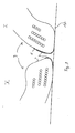
- FIG. 1 shows in section an example of a bead 3 of a tire 1 according to the invention.
- This bead 3 has a structure which was recently proposed in the patent application EP 0582196.
- This bead 3 is devoid of the usual turning the carcass around a rod.
- the carcass reinforcing elements 11 are arranged in an alignment. By imagining the arrangement of all of these elements 11 in space, these roughly draw, within the alignment, a truncated cone partial axis coincides with the axis of rotation of the tire.
- the elements carcass reinforcers 11 are bordered laterally by three piles 12, 13 and 14 circumferential reinforcing elements 15. These piles are produced for example by spiral winding.
- the battery 12 is placed on the side of the internal cavity 6 of the pneumatic relative to the carcass reinforcement elements 11.
- the piles 13 and 14 are located on the outside of the tire. Mixtures rubbery placed between the batteries 12, 13, 14 and the reinforcing elements of carcass 11 ensure the resumption of the forces between these reinforcing elements 11, 12, 13 and 14 oriented perpendicular to each other.
- the bead is delimited by a radially inner wall or seat 4 substantially frustoconical intended to rest on the radially outer wall or seat 16 of a rim 17 (see Figure 2).
- This wall 4 is separated into two parts, an axially outer part on the outside of the tire and a axially inner part 9 on the side of the internal cavity of the tire.
- the the bead is also delimited, on the side of the internal cavity 6 of the tire 1, by an axially inner wall 5 and, on the outside of the tire, by a axially outer wall 18.
- a rubber mixture 8 is disposed adjacent to the part 9 of the seat 4 on the side of the internal cavity 6 of the tire 1 as well as at the radially lowest part 10 of the axially inner wall 5.
- the bead 3 is extended radially by the sidewall 2 of the tire 1.
- This rubber mixture 8 has a very usual formulation with the exception close that it further comprises a partially soluble compound which will migrate to the surface of parts 9 and 10 to form a sliding layer 7.
- This compound is included in a proportion greater than or equal to 3 pce (parts for hundred parts by weight of elastomer). It should be noted that this compound is only very sparingly soluble in a rubber mixture based on butyl rubber. In the if mixture 8 contains butyl rubber, it is therefore necessary to limit the maximum content of butyl rubber to 50 phr.
- This compound is, for example, an ethylene bis-oleamide (Crodamide® EBO).
- the surface migration of this compound provides a slip layer stable with a particularly low coefficient of friction, less than 0.1.
- the seat 4 has an axial length b .
- This length is defined in FIGS. 1 and 2 as the distance axially separating the end of the axially inner wall 5 from the zone 26 of the axially outer wall 18 intended to be disposed on the radial part 27 of the rim hook 25.
- the length axial a of the part 9 adjacent to the rubber mixture 8 and thus coated with a sliding layer 7 is of the order of 3 to 4 mm.
- This length a must be limited to approximately a quarter of the axial length b of the seat 4 so as not to degrade the performance in service of the tire, in particular the anti-loosening efficiency of the hump 29, and to avoid any rotation on the rim.
- the radial height of the rubber mixture 8 along the axially wall inner 5 is here of the order of 10 mm. This height can be very variable in function of the rotational stiffness of the bead considered. She is, preferably, the higher the rotational rigidity of the bead of the pneumatic is weak.
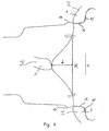
- FIG. 2 illustrates the phenomenon of tilting of the bead 3 during the first phase of disassembly, the loosening of the bead 3 of the hook 25 and of the seat 16 of the rim 17.
- the stacks 12, 13 and 14 are shown more schematically without distinguishing as in Figure 1 the elements circumferential reinforcers 15.
- the tire 1 in position I is mounted on the rim 17.
- position II after having undergone an offset d , that is to say an axial displacement of length b of the bead, it can be seen that the bead 3 is partially tilted so that only the connection zone 28 between the axially inner wall 5 and the end of the seat 4 is in contact with the rim 17.
- This zone 28 is covered with a sliding layer 7 consisting of the compound described above. Consequently, the coefficient of friction between the bead and the rim is very low, which facilitates the loosening of the bead.
- Figure 4 schematically illustrates the evolution of the position of the bead 3 relative to the rim hook 25 during the first phase of disassembly.
- This corresponds to position I of Figure 2.
- the center of the diagram corresponds to area A of application of a push against the bead 3, this zone extends over an arc of approximately 60 degrees.
- a bead 3 is presented in the inverted position. That corresponds in position II of FIG. 2.
- offset of the bead relative to the rim hook the spacing of this bead relative to its initial position in place against the seat and the rim hook.
- FIG. 4 illustrates the loose area B of the bead, that is to say, the arc where the bead is moved away from its initial position as well as the evolution of the offset as a function of the angular position relative to the pusher. We call this arc 2 ⁇ .
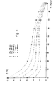
- FIG. 5 shows the evolution of the elongation ⁇ (in%) of the wires of a rod as a function of the loosening angle ⁇ (this angle corresponds to half the arc of the circumference of the bead actually loosened; ⁇ is in degrees) and the offset d (in millimeters) imposed on the bead by the pusher (see Figure 4).
- Tires with beads comprising a sliding layer according to the invention have been tested. For these tires, with a 40 mm offset, values of ⁇ greater than 60 degrees were measured.
Landscapes
- Engineering & Computer Science (AREA)
- Mechanical Engineering (AREA)
- Tires In General (AREA)
- Road Paving Machines (AREA)
Applications Claiming Priority (2)
| Application Number | Priority Date | Filing Date | Title |
|---|---|---|---|
| FR9613388 | 1996-10-30 | ||
| FR9613388 | 1996-10-30 |
Publications (2)
| Publication Number | Publication Date |
|---|---|
| EP0839674A1 EP0839674A1 (fr) | 1998-05-06 |
| EP0839674B1 true EP0839674B1 (fr) | 2003-04-02 |
Family
ID=9497278
Family Applications (1)
| Application Number | Title | Priority Date | Filing Date |
|---|---|---|---|
| EP19970118228 Expired - Lifetime EP0839674B1 (fr) | 1996-10-30 | 1997-10-21 | Pneumatique à bourrelets conçus pour faciliter le démontage |
Country Status (5)
| Country | Link |
|---|---|
| EP (1) | EP0839674B1 (enExample) |
| JP (1) | JP4065588B2 (enExample) |
| BR (1) | BR9705175A (enExample) |
| DE (1) | DE69720366T2 (enExample) |
| ES (1) | ES2196233T3 (enExample) |
Families Citing this family (1)
| Publication number | Priority date | Publication date | Assignee | Title |
|---|---|---|---|---|
| JP4700410B2 (ja) * | 2005-05-27 | 2011-06-15 | 住友ゴム工業株式会社 | 空気入りタイヤ |
Family Cites Families (5)
| Publication number | Priority date | Publication date | Assignee | Title |
|---|---|---|---|---|
| JPS5447203A (en) * | 1977-09-21 | 1979-04-13 | Yokohama Rubber Co Ltd:The | Tubeless radial tire for truck or bus |
| JPS584608A (ja) * | 1981-06-30 | 1983-01-11 | Sumitomo Rubber Ind Ltd | タイヤ |
| FR2685666A1 (fr) * | 1991-12-31 | 1993-07-02 | Michelin & Cie | Bourrelets de pneumatiques sans chambre a air et leurs procedes de realisation. |
| JP2878522B2 (ja) * | 1992-03-16 | 1999-04-05 | 丸五ゴム工業株式会社 | 自動車部品用ゴムブッシュ |
| DE4413058A1 (de) * | 1994-04-15 | 1995-10-19 | Basf Ag | Polypropylenformmassen |
-
1997
- 1997-10-21 EP EP19970118228 patent/EP0839674B1/fr not_active Expired - Lifetime
- 1997-10-21 DE DE1997620366 patent/DE69720366T2/de not_active Expired - Lifetime
- 1997-10-21 ES ES97118228T patent/ES2196233T3/es not_active Expired - Lifetime
- 1997-10-30 JP JP29811297A patent/JP4065588B2/ja not_active Expired - Fee Related
- 1997-10-30 BR BR9705175A patent/BR9705175A/pt not_active IP Right Cessation
Also Published As
| Publication number | Publication date |
|---|---|
| DE69720366T2 (de) | 2003-12-18 |
| JPH10138717A (ja) | 1998-05-26 |
| DE69720366D1 (de) | 2003-05-08 |
| JP4065588B2 (ja) | 2008-03-26 |
| EP0839674A1 (fr) | 1998-05-06 |
| BR9705175A (pt) | 1999-03-09 |
| ES2196233T3 (es) | 2003-12-16 |
Similar Documents
| Publication | Publication Date | Title |
|---|---|---|
| EP0748287B1 (fr) | Pneumatique avec des bourrelets de structure amelioree et ensemble d'un tel pneumatique avec une jante adaptee | |
| CA2178217C (fr) | Jante, anneau de soutien et ensemble comprenant lesdits elements | |
| CA2065307C (fr) | Ensemble roulant compose d'un pneumatique dont les bourrelets ont des bases tronconiques, d'une jante de montage a sieges plats, et d'adaptateurs annulaires en caoutchouc et adaptateur concu pour cet ensemble | |
| WO1994013498A1 (fr) | Pneumatique, jante, anneau de soutien et ensemble comprenant lesdits elements | |
| EP3484726B1 (fr) | Pneumatique dont la zone du bourrelet est allégée | |
| WO1995015863A1 (fr) | Pneumatique, jante, anneau de soutien et ensemble comprenant lesdits elements | |
| EP0635384B1 (fr) | Dispositif de soutien d'une bande de roulement de pneumatique | |
| EP1144206B1 (fr) | Pneumatique avec des bourrelets de structure amelioree | |
| WO2017191421A1 (fr) | Pneumatique dont la zone du bourrelet est allégée | |
| EP0724973B1 (fr) | Bourrelets de pneumatique | |
| EP0498214B1 (fr) | Ensemble d'un pneumatique et d'une jante permettant d'éviter le délogement des bourrelets du pneumatique | |
| EP0839674B1 (fr) | Pneumatique à bourrelets conçus pour faciliter le démontage | |
| FR2819450A1 (fr) | Pneumatique avec au moins un bourrelet a siege incline vers l'exterieur et un flanc avec anneau additionnel | |
| EP3484728B1 (fr) | Pneumatique dont la zone du bourrelet est allegee | |
| EP0835769B9 (fr) | Dispositif de soutien de bande de roulement | |
| WO2020094952A1 (fr) | Pneumatique dont la zone du bourrelet est allégée | |
| CA2401218A1 (fr) | Jante avec sieges inclines vers l'exterieur et ensembles comprenant une telle jante et un appui de soutien gonfle | |
| EP0637519B1 (fr) | Pneumatique comportant un bourrelet de forme perfectionnée | |
| FR3050961A1 (fr) | Pneumatique dont la zone du bourrelet est allegee | |
| WO2020094951A1 (fr) | Pneumatique dont la zone du bourrelet est allegee | |
| WO2025114254A1 (fr) | Pneumatique dont la zone du bourrelet est allegee | |
| WO1994008803A1 (fr) | Cale de montage de pneumatiques | |
| FR2888777A1 (fr) | Pneumatique a mobilite etendue avec flanc souple |
Legal Events
| Date | Code | Title | Description |
|---|---|---|---|
| PUAI | Public reference made under article 153(3) epc to a published international application that has entered the european phase |
Free format text: ORIGINAL CODE: 0009012 |
|
| AK | Designated contracting states |
Kind code of ref document: A1 Designated state(s): DE ES FR GB IT SE |
|
| 17P | Request for examination filed |
Effective date: 19981106 |
|
| AKX | Designation fees paid |
Free format text: DE ES FR GB IT SE |
|
| RBV | Designated contracting states (corrected) |
Designated state(s): DE ES FR GB IT SE |
|
| 17Q | First examination report despatched |
Effective date: 20010129 |
|
| GRAG | Despatch of communication of intention to grant |
Free format text: ORIGINAL CODE: EPIDOS AGRA |
|
| GRAG | Despatch of communication of intention to grant |
Free format text: ORIGINAL CODE: EPIDOS AGRA |
|
| GRAH | Despatch of communication of intention to grant a patent |
Free format text: ORIGINAL CODE: EPIDOS IGRA |
|
| GRAH | Despatch of communication of intention to grant a patent |
Free format text: ORIGINAL CODE: EPIDOS IGRA |
|
| GRAA | (expected) grant |
Free format text: ORIGINAL CODE: 0009210 |
|
| AK | Designated contracting states |
Designated state(s): DE ES FR GB IT SE |
|
| REG | Reference to a national code |
Ref country code: GB Ref legal event code: FG4D Free format text: NOT ENGLISH |
|
| REF | Corresponds to: |
Ref document number: 69720366 Country of ref document: DE Date of ref document: 20030508 Kind code of ref document: P |
|
| REG | Reference to a national code |
Ref country code: SE Ref legal event code: TRGR |
|
| GBT | Gb: translation of ep patent filed (gb section 77(6)(a)/1977) | ||
| REG | Reference to a national code |
Ref country code: ES Ref legal event code: FG2A Ref document number: 2196233 Country of ref document: ES Kind code of ref document: T3 |
|
| PLBE | No opposition filed within time limit |
Free format text: ORIGINAL CODE: 0009261 |
|
| STAA | Information on the status of an ep patent application or granted ep patent |
Free format text: STATUS: NO OPPOSITION FILED WITHIN TIME LIMIT |
|
| 26N | No opposition filed |
Effective date: 20040105 |
|
| PGFP | Annual fee paid to national office [announced via postgrant information from national office to epo] |
Ref country code: ES Payment date: 20081027 Year of fee payment: 12 |
|
| PGFP | Annual fee paid to national office [announced via postgrant information from national office to epo] |
Ref country code: SE Payment date: 20081014 Year of fee payment: 12 |
|
| PGFP | Annual fee paid to national office [announced via postgrant information from national office to epo] |
Ref country code: GB Payment date: 20081021 Year of fee payment: 12 |
|
| EUG | Se: european patent has lapsed | ||
| PG25 | Lapsed in a contracting state [announced via postgrant information from national office to epo] |
Ref country code: GB Free format text: LAPSE BECAUSE OF NON-PAYMENT OF DUE FEES Effective date: 20091021 |
|
| PGFP | Annual fee paid to national office [announced via postgrant information from national office to epo] |
Ref country code: IT Payment date: 20101026 Year of fee payment: 14 |
|
| REG | Reference to a national code |
Ref country code: ES Ref legal event code: FD2A Effective date: 20110401 |
|
| PG25 | Lapsed in a contracting state [announced via postgrant information from national office to epo] |
Ref country code: SE Free format text: LAPSE BECAUSE OF NON-PAYMENT OF DUE FEES Effective date: 20091022 |
|
| PG25 | Lapsed in a contracting state [announced via postgrant information from national office to epo] |
Ref country code: ES Free format text: LAPSE BECAUSE OF NON-PAYMENT OF DUE FEES Effective date: 20110321 |
|
| PG25 | Lapsed in a contracting state [announced via postgrant information from national office to epo] |
Ref country code: ES Free format text: LAPSE BECAUSE OF NON-PAYMENT OF DUE FEES Effective date: 20091022 |
|
| PGFP | Annual fee paid to national office [announced via postgrant information from national office to epo] |
Ref country code: DE Payment date: 20121023 Year of fee payment: 16 Ref country code: FR Payment date: 20121031 Year of fee payment: 16 |
|
| PG25 | Lapsed in a contracting state [announced via postgrant information from national office to epo] |
Ref country code: IT Free format text: LAPSE BECAUSE OF NON-PAYMENT OF DUE FEES Effective date: 20121021 |
|
| REG | Reference to a national code |
Ref country code: DE Ref legal event code: R119 Ref document number: 69720366 Country of ref document: DE Effective date: 20140501 |
|
| REG | Reference to a national code |
Ref country code: FR Ref legal event code: ST Effective date: 20140630 |
|
| PG25 | Lapsed in a contracting state [announced via postgrant information from national office to epo] |
Ref country code: DE Free format text: LAPSE BECAUSE OF NON-PAYMENT OF DUE FEES Effective date: 20140501 Ref country code: FR Free format text: LAPSE BECAUSE OF NON-PAYMENT OF DUE FEES Effective date: 20131031 |