EP0839674B1 - Tyre with a bead that makes removing easier - Google Patents
Tyre with a bead that makes removing easier Download PDFInfo
- Publication number
- EP0839674B1 EP0839674B1 EP19970118228 EP97118228A EP0839674B1 EP 0839674 B1 EP0839674 B1 EP 0839674B1 EP 19970118228 EP19970118228 EP 19970118228 EP 97118228 A EP97118228 A EP 97118228A EP 0839674 B1 EP0839674 B1 EP 0839674B1
- Authority
- EP
- European Patent Office
- Prior art keywords
- bead
- wall
- tyre
- axially
- radially
- Prior art date
- Legal status (The legal status is an assumption and is not a legal conclusion. Google has not performed a legal analysis and makes no representation as to the accuracy of the status listed.)
- Expired - Lifetime
Links
Images


Classifications
-
- B—PERFORMING OPERATIONS; TRANSPORTING
- B60—VEHICLES IN GENERAL
- B60C—VEHICLE TYRES; TYRE INFLATION; TYRE CHANGING; CONNECTING VALVES TO INFLATABLE ELASTIC BODIES IN GENERAL; DEVICES OR ARRANGEMENTS RELATED TO TYRES
- B60C15/00—Tyre beads, e.g. ply turn-up or overlap
- B60C15/0009—Tyre beads, e.g. ply turn-up or overlap features of the carcass terminal portion
- B60C15/0018—Tyre beads, e.g. ply turn-up or overlap features of the carcass terminal portion not folded around the bead core, e.g. floating or down ply
-
- B—PERFORMING OPERATIONS; TRANSPORTING
- B44—DECORATIVE ARTS
- B44D—PAINTING OR ARTISTIC DRAWING, NOT OTHERWISE PROVIDED FOR; PRESERVING PAINTINGS; SURFACE TREATMENT TO OBTAIN SPECIAL ARTISTIC SURFACE EFFECTS OR FINISHES
- B44D2/00—Special techniques in artistic painting or drawing, e.g. oil painting, water painting, pastel painting, relief painting
-
- B—PERFORMING OPERATIONS; TRANSPORTING
- B44—DECORATIVE ARTS
- B44D—PAINTING OR ARTISTIC DRAWING, NOT OTHERWISE PROVIDED FOR; PRESERVING PAINTINGS; SURFACE TREATMENT TO OBTAIN SPECIAL ARTISTIC SURFACE EFFECTS OR FINISHES
- B44D3/00—Accessories or implements for use in connection with painting or artistic drawing, not otherwise provided for; Methods or devices for colour determination, selection, or synthesis, e.g. use of colour tables
-
- B—PERFORMING OPERATIONS; TRANSPORTING
- B60—VEHICLES IN GENERAL
- B60C—VEHICLE TYRES; TYRE INFLATION; TYRE CHANGING; CONNECTING VALVES TO INFLATABLE ELASTIC BODIES IN GENERAL; DEVICES OR ARRANGEMENTS RELATED TO TYRES
- B60C15/00—Tyre beads, e.g. ply turn-up or overlap
- B60C15/02—Seating or securing beads on rims
- B60C15/024—Bead contour, e.g. lips, grooves, or ribs
-
- B—PERFORMING OPERATIONS; TRANSPORTING
- B60—VEHICLES IN GENERAL
- B60C—VEHICLE TYRES; TYRE INFLATION; TYRE CHANGING; CONNECTING VALVES TO INFLATABLE ELASTIC BODIES IN GENERAL; DEVICES OR ARRANGEMENTS RELATED TO TYRES
- B60C15/00—Tyre beads, e.g. ply turn-up or overlap
- B60C15/06—Flipper strips, fillers, or chafing strips and reinforcing layers for the construction of the bead
- B60C15/0603—Flipper strips, fillers, or chafing strips and reinforcing layers for the construction of the bead characterised by features of the bead filler or apex
Definitions
- the present invention relates to tires. More specifically, it relates to an improved design of their beads intended to facilitate their disassembly.
- Dismantling in particular involves applying a fairly significant effort to the bead at or just above the rim hook.
- This effort is oriented parallel to the axis of rotation and is usually applied by a push on successive portions of the circumference of the bead corresponding to arcs of a circle of about 60 degrees.
- This is the first phase of the disassembly whose purpose is to loosen the bead, that is to make it leave radially inner seat or wall away from the rim flange and bring it to the central hollow of the rim.
- the tire bead is subjected to relatively extended forces localized and very important.
- Document JP58-4608 presents a tire, the part of the beads of which intended to be in contact with the seat of a rim is coated with a layer porous polytetrafluoroethylene. The purpose of this layer is to facilitate the place the tire on the rim. The characteristics of the preamble to the claim 1 correspond to this state of the art.
- the subject of the invention is an improvement of the beads of a tire intended to facilitate its successive dismantling without damaging its beads and without sacrificing performance in use.
- a tire comprising a crown and extended sidewalls by beads defining an internal cavity, each bead being delimited, on the radially inner side, by a radially inner wall having a part axially outer and an axially inner part, said wall being substantially frustoconical and being intended to rest on a rim and, on the side of the internal cavity of the tire, by an axially inner wall, is characterized in that a sliding layer covers the axially inner part of the radially inner wall and at least the radially lowest part of the axially inner wall.
- the sliding layer covers only the axially inner part of the wall radially inner, that is to say the part of this wall disposed on the side of the internal cavity of the tire. This limitation is very important in order not to degrade the properties of use of the tire, in particular the anti-loosening efficiency "humps" and to avoid any rotation on the rim.
- the part of the axially inner wall covered by said sliding layer extends radially over a length of at least 10 mm.
- the bead When the tire is removed, the bead will, under the action of the tool disassembly (the pusher), start a tilting movement centered on the connection zone between the axially inner wall and the radially wall inside of the bead.
- the amplitude of this tilt depends on the rigidity in rotation of the bead. In the most common case, a rigid bead in rotation, tilting is very limited. This movement however induces a increased contact pressures in the area of the wall radially interior closest to the internal cavity of the tire, area comprising the sliding layer, and a decrease in clamping forces between the rest of the radially inner wall and rim.
- the forces transmitted by the pusher can cause a tilting complete and bring the axially inner wall of the bead into contact with the rim.
- the contact area between the bead and the rim again has a low coefficient of friction, which facilitates the loosening of the bead, crossing the hump and as before appreciably increases the value of the disconnected bead circle arc for a given value of the offset imposed by the pusher.
- the presence of the layer of slip reduces the elongations imposed on the rod wires during a disassembly, which limits their risk of damage.
- the function of the sliding layer is to provide a coefficient of friction low between the bead and the rim throughout the life of the tire.
- This layer may in particular consist of a rubber tongue based of dimethyl siloxane as proposed by application JP 4-40208.
- the sliding layer is formed by the migration in surface of a compound present in the rubber mixture adjacent to the parts covered with the radially and axially inner walls of the beads.
- the compound present in the rubber mixture adjacent to the parts of the walls of the bead covered with the sliding layer may be an acid amide fatty and preferably an oleamide.
- ethylene bis oleamide has the advantage of having a temperature of high fusion and thus to offer the sliding layer, after its constitution by migration, good stability.
- the adjacent rubber mixture comprises at least one elastomer chosen from the group of natural rubbers, polybutadiene, SBR, butyl, the content of butyl rubber being less than or equal to 50 parts per hundred parts by weight of elastomer, as well as at least 3 parts per hundred parts by weight of elastomer of the compound.
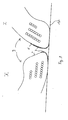
- FIG. 1 shows in section an example of a bead 3 of a tire 1 according to the invention.
- This bead 3 has a structure which was recently proposed in the patent application EP 0582196.
- This bead 3 is devoid of the usual turning the carcass around a rod.
- the carcass reinforcing elements 11 are arranged in an alignment. By imagining the arrangement of all of these elements 11 in space, these roughly draw, within the alignment, a truncated cone partial axis coincides with the axis of rotation of the tire.
- the elements carcass reinforcers 11 are bordered laterally by three piles 12, 13 and 14 circumferential reinforcing elements 15. These piles are produced for example by spiral winding.
- the battery 12 is placed on the side of the internal cavity 6 of the pneumatic relative to the carcass reinforcement elements 11.
- the piles 13 and 14 are located on the outside of the tire. Mixtures rubbery placed between the batteries 12, 13, 14 and the reinforcing elements of carcass 11 ensure the resumption of the forces between these reinforcing elements 11, 12, 13 and 14 oriented perpendicular to each other.
- the bead is delimited by a radially inner wall or seat 4 substantially frustoconical intended to rest on the radially outer wall or seat 16 of a rim 17 (see Figure 2).
- This wall 4 is separated into two parts, an axially outer part on the outside of the tire and a axially inner part 9 on the side of the internal cavity of the tire.
- the the bead is also delimited, on the side of the internal cavity 6 of the tire 1, by an axially inner wall 5 and, on the outside of the tire, by a axially outer wall 18.
- a rubber mixture 8 is disposed adjacent to the part 9 of the seat 4 on the side of the internal cavity 6 of the tire 1 as well as at the radially lowest part 10 of the axially inner wall 5.
- the bead 3 is extended radially by the sidewall 2 of the tire 1.
- This rubber mixture 8 has a very usual formulation with the exception close that it further comprises a partially soluble compound which will migrate to the surface of parts 9 and 10 to form a sliding layer 7.
- This compound is included in a proportion greater than or equal to 3 pce (parts for hundred parts by weight of elastomer). It should be noted that this compound is only very sparingly soluble in a rubber mixture based on butyl rubber. In the if mixture 8 contains butyl rubber, it is therefore necessary to limit the maximum content of butyl rubber to 50 phr.
- This compound is, for example, an ethylene bis-oleamide (Crodamide® EBO).
- the surface migration of this compound provides a slip layer stable with a particularly low coefficient of friction, less than 0.1.
- the seat 4 has an axial length b .
- This length is defined in FIGS. 1 and 2 as the distance axially separating the end of the axially inner wall 5 from the zone 26 of the axially outer wall 18 intended to be disposed on the radial part 27 of the rim hook 25.
- the length axial a of the part 9 adjacent to the rubber mixture 8 and thus coated with a sliding layer 7 is of the order of 3 to 4 mm.
- This length a must be limited to approximately a quarter of the axial length b of the seat 4 so as not to degrade the performance in service of the tire, in particular the anti-loosening efficiency of the hump 29, and to avoid any rotation on the rim.
- the radial height of the rubber mixture 8 along the axially wall inner 5 is here of the order of 10 mm. This height can be very variable in function of the rotational stiffness of the bead considered. She is, preferably, the higher the rotational rigidity of the bead of the pneumatic is weak.
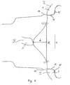
- FIG. 2 illustrates the phenomenon of tilting of the bead 3 during the first phase of disassembly, the loosening of the bead 3 of the hook 25 and of the seat 16 of the rim 17.
- the stacks 12, 13 and 14 are shown more schematically without distinguishing as in Figure 1 the elements circumferential reinforcers 15.
- the tire 1 in position I is mounted on the rim 17.
- position II after having undergone an offset d , that is to say an axial displacement of length b of the bead, it can be seen that the bead 3 is partially tilted so that only the connection zone 28 between the axially inner wall 5 and the end of the seat 4 is in contact with the rim 17.
- This zone 28 is covered with a sliding layer 7 consisting of the compound described above. Consequently, the coefficient of friction between the bead and the rim is very low, which facilitates the loosening of the bead.
- Figure 4 schematically illustrates the evolution of the position of the bead 3 relative to the rim hook 25 during the first phase of disassembly.
- This corresponds to position I of Figure 2.
- the center of the diagram corresponds to area A of application of a push against the bead 3, this zone extends over an arc of approximately 60 degrees.
- a bead 3 is presented in the inverted position. That corresponds in position II of FIG. 2.
- offset of the bead relative to the rim hook the spacing of this bead relative to its initial position in place against the seat and the rim hook.
- FIG. 4 illustrates the loose area B of the bead, that is to say, the arc where the bead is moved away from its initial position as well as the evolution of the offset as a function of the angular position relative to the pusher. We call this arc 2 ⁇ .
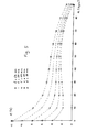
- FIG. 5 shows the evolution of the elongation ⁇ (in%) of the wires of a rod as a function of the loosening angle ⁇ (this angle corresponds to half the arc of the circumference of the bead actually loosened; ⁇ is in degrees) and the offset d (in millimeters) imposed on the bead by the pusher (see Figure 4).
- Tires with beads comprising a sliding layer according to the invention have been tested. For these tires, with a 40 mm offset, values of ⁇ greater than 60 degrees were measured.
Description
La présente invention se rapporte aux pneumatiques. Plus particulièrement, elle concerne une conception perfectionnée de leurs bourrelets destinée à faciliter leur démontage.The present invention relates to tires. More specifically, it relates to an improved design of their beads intended to facilitate their disassembly.
On connaít le rôle des bourrelets des pneumatiques : il s'agit d'assurer "l'accrochage" du pneumatique sur la jante sur laquelle il est monté. A cette fin, les câbles de carcasse rejoignent tous la partie basse du bourrelet, où ils sont fermement ancrés, afin que la carcasse résiste aux efforts de tension en service.We know the role of tire beads: this is to ensure "attachment" of the tire on the rim on which it is mounted. To this end, the carcass cables all join the lower part of the bead, where they are firmly anchored, so that the carcass withstands the stresses in service.
En dehors des sollicitations dues à l'utilisation proprement dite du pneumatique, celui-ci doit en outre être capable de subir un nombre indéterminé de démontages suivis de remontages pour en poursuivre l'utilisation.Apart from the stresses due to the actual use of the tire, it must also be capable of undergoing an unspecified number of dismantling followed by reassembly to continue using it.
Le démontage notamment implique d'appliquer un effort assez important sur le bourrelet au niveau du crochet de la jante, ou juste au-dessus de celui-ci. Cet effort est orienté parallèlement à l'axe de rotation et est habituellement appliqué par un poussoir sur des portions successives de la circonférence du bourrelet correspondant à des arcs de cercle d'environ 60 degrés. C'est la première phase du démontage dont le but est de décoincer le bourrelet, c'est à dire de lui faire quitter son siège ou paroi radialement intérieure en l'éloignant du rebord de jante et de l'amener jusqu'au creux central de la jante. Pendant cette première phase, le bourrelet du pneumatique est soumis à des efforts d'extension relativement localisés et très importants.Dismantling in particular involves applying a fairly significant effort to the bead at or just above the rim hook. This effort is oriented parallel to the axis of rotation and is usually applied by a push on successive portions of the circumference of the bead corresponding to arcs of a circle of about 60 degrees. This is the first phase of the disassembly whose purpose is to loosen the bead, that is to make it leave radially inner seat or wall away from the rim flange and bring it to the central hollow of the rim. During this first phase, the tire bead is subjected to relatively extended forces localized and very important.
Ensuite, on utilise en général des leviers pour contraindre le bourrelet à franchir le rebord de jante. En effet, dans le cas des jantes en une seule pièce (cas de loin le plus courant pour les pneumatiques de tourisme), la forme de la jante est conçue pour permettre le montage et le démontage grâce à une ovalisation du bourrelet, sans augmentation du périmètre de celui-ci. Cela conditionne notamment le dessin du creux central de montage et des rebords bordant latéralement la jante et définissant la position de montage du bourrelet. Pendant cette seconde phase, le bourrelet subit une déformation d'ensemble qui est bien moins pénalisante que les sollicitations survenant pendant la première phase.Then, we generally use levers to force the bead to cross the rim flange. Indeed, in the case of rims in one piece (case by far the more common for passenger car tires), the rim shape is designed to allow assembly and disassembly by ovalizing the bead, without increasing the scope of it. This notably conditions the drawing the central mounting recess and the flanges laterally bordering the rim and defining the mounting position of the bead. During this second phase, the bead undergoes an overall deformation which is much less penalizing than the stresses occurring during the first phase.
Il est bien connu qu'un démontage réalisé dans des conditions peu soigneuses peut endommager de façon irréversible le bourrelet (ruptures de câbles de carcasse, déchirures de la pointe intérieure du bourrelet retenue usuellement par un hump...) à cause des efforts d'extension localisés et importants subis lors de la première phase du démontage.It is well known that disassembly carried out in careless conditions can irreversibly damaging the bead (broken carcass cables, tears of the inner point of the bead usually retained by a hump ...) because of the localized and significant extension efforts undergone during the first dismantling phase.
C'est ce qui est susceptible de se produire lorsque l'on veut décoincer le bourrelet en une seule fois avec le poussoir en imposant un déport localisé élevé du bourrelet relativement au crochet de jante. Après quelques mois ou années d'utilisation, il est courant que les bourrelets adhérent fortement contre les sièges et crochets de jante. En conséquence, ce déport important et localisé impose notamment un allongement de la longueur des fils de tringles qui peut entraíner des dommages irréparables au bourrelet du pneumatique.This is what is likely to happen when you want to loosen the bead all at once with the pusher by imposing a high localized offset of the bead relative to the rim hook. After a few months or years of use, it is common that the beads strongly adhere against the seats and rim hooks. Consequently, this large and localized offset imposes in particular an extension of the length of the rod wires which can cause irreparable damage to the tire bead.
Le document JP58-4608 présente un pneumatique dont la partie des bourrelets
destinée à être en contact avec le siège d'une jante est revêtue d'une couche
poreuse de polytétrafluoroéthylène. Cette couche a pour but de faciliter la mise en
place du pneumatique sur la jante. Les caractéristiques du préambule de la
revendication 1 correspondent à cet état de la technique.Document JP58-4608 presents a tire, the part of the beads of which
intended to be in contact with the seat of a rim is coated with a layer
porous polytetrafluoroethylene. The purpose of this layer is to facilitate the
place the tire on the rim. The characteristics of the preamble to the
L'invention a pour objet un perfectionnement des bourrelets d'un pneumatique destiné à faciliter ses démontages successifs sans endommagement de ses bourrelets et sans sacrifier ses performances en usage.The subject of the invention is an improvement of the beads of a tire intended to facilitate its successive dismantling without damaging its beads and without sacrificing performance in use.
Selon l'invention, un pneumatique comportant un sommet et des flancs prolongés par des bourrelets définissant une cavité interne, chaque bourrelet étant délimité, du côté radialement intérieur, par une paroi radialement intérieure ayant une partie axialement extérieure et une partie axialement intérieure, ladite paroi étant sensiblement tronconique et étant destinée à reposer sur une jante et, du côté de la cavité interne du pneumatique, par une paroi axialement intérieure, est caractérisé en ce qu'une couche de glissement recouvre la partie axialement intérieure de la paroi radialement intérieure et au moins la partie radialement la plus basse de la paroi axialement intérieure.According to the invention, a tire comprising a crown and extended sidewalls by beads defining an internal cavity, each bead being delimited, on the radially inner side, by a radially inner wall having a part axially outer and an axially inner part, said wall being substantially frustoconical and being intended to rest on a rim and, on the side of the internal cavity of the tire, by an axially inner wall, is characterized in that a sliding layer covers the axially inner part of the radially inner wall and at least the radially lowest part of the axially inner wall.
La couche de glissement ne revêt que la partie axialement intérieure de la paroi radialement intérieure, c'est-à-dire la partie de cette paroi disposée du côté de la cavité interne du pneumatique. Cette limitation est très importante pour ne pas dégrader les propriétés d'usage du pneumatique, notamment l'efficacité anti-décoincement des « humps» et pour éviter toute rotation sur jante.The sliding layer covers only the axially inner part of the wall radially inner, that is to say the part of this wall disposed on the side of the internal cavity of the tire. This limitation is very important in order not to degrade the properties of use of the tire, in particular the anti-loosening efficiency "humps" and to avoid any rotation on the rim.
Préférentiellement, la partie de la paroi axialement intérieure recouverte par ladite couche de glissement s'étend radialement sur une longueur d'au moins 10 mm.Preferably, the part of the axially inner wall covered by said sliding layer extends radially over a length of at least 10 mm.
Lors d'un démontage du pneumatique, le bourrelet va, sous l'action de l'outil de démontage (le poussoir), entamer un mouvement de basculement centré sur la zone de liaison entre la paroi axialement intérieure et la paroi radialement intérieure du bourrelet. L'amplitude de ce basculement est fonction de la rigidité en rotation du bourrelet. Dans le cas, le plus courant, d'un bourrelet rigide en rotation, le basculement est très limité. Ce mouvement induit cependant une augmentation des pressions de contact dans la zone de la paroi radialement intérieure la plus proche de la cavité interne du pneumatique, zone comportant la couche de glissement, et une diminution des efforts de serrage entre le reste de la paroi radialement intérieure et la jante. En conséquence, les efforts dus au serrage du bourrelet sur la jante sont majoritairement transmis dans une zone où le coefficient de glissement entre la paroi radialement intérieure et la jante est très faible, ce qui facilite fortement le décoincement du bourrelet, le franchissement du hump et augmente sensiblement la valeur de l'arc de cercle de bourrelet décoincé pour une valeur donnée du déport imposé par le poussoir.When the tire is removed, the bead will, under the action of the tool disassembly (the pusher), start a tilting movement centered on the connection zone between the axially inner wall and the radially wall inside of the bead. The amplitude of this tilt depends on the rigidity in rotation of the bead. In the most common case, a rigid bead in rotation, tilting is very limited. This movement however induces a increased contact pressures in the area of the wall radially interior closest to the internal cavity of the tire, area comprising the sliding layer, and a decrease in clamping forces between the rest of the radially inner wall and rim. Consequently, the forces due to tightening of the bead on the rim are mainly transmitted in an area where the sliding coefficient between the radially inner wall and the rim is very weak, which greatly facilitates the loosening of the bead, the crossing of the hump and appreciably increases the value of the disconnected bead circle arc for a given value of the offset imposed by the pusher.
Dans le cas où le pneumatique présente des bourrelets de faible rigidité en rotation, les efforts transmis par le poussoir peuvent entraíner un basculement complet et mettre en contact la paroi axialement intérieure du bourrelet avec la jante. Comme la paroi axialement intérieure du bourrelet est elle aussi recouverte d'une couche de glissement, la zone de contact entre le bourrelet et la jante présente de nouveau un faible coefficient de frottement, ce qui facilite le décoincement du bourrelet, le franchissement du hump et comme précédemment augmente sensiblement la valeur de l'arc de cercle de bourrelet décoincé pour une valeur donnée du déport imposé par le poussoir.In the case where the tire has beads of low rigidity in rotation, the forces transmitted by the pusher can cause a tilting complete and bring the axially inner wall of the bead into contact with the rim. As the axially inner wall of the bead is also covered a sliding layer, the contact area between the bead and the rim again has a low coefficient of friction, which facilitates the loosening of the bead, crossing the hump and as before appreciably increases the value of the disconnected bead circle arc for a given value of the offset imposed by the pusher.
Ainsi, quelle que soit l'architecture du bourrelet, la présence de la couche de glissement diminue les allongements imposés aux fils de tringle lors d'un démontage, ce qui limite leurs risques d'endommagement.Thus, whatever the architecture of the bead, the presence of the layer of slip reduces the elongations imposed on the rod wires during a disassembly, which limits their risk of damage.
La couche de glissement a pour fonction de procurer un coefficient de frottement bas entre le bourrelet et la jante pendant toute la durée de vie du pneumatique. Cette couche peut notamment être constituée d'une languette de caoutchouc à base de siloxane de diméthyle telle que proposée par la demande JP 4-40208.The function of the sliding layer is to provide a coefficient of friction low between the bead and the rim throughout the life of the tire. This layer may in particular consist of a rubber tongue based of dimethyl siloxane as proposed by application JP 4-40208.
Préférentiellement, la couche de glissement est constituée par la migration en surface d'un composé présent dans le mélange de caoutchouc adjacent aux parties recouvertes des parois radialement et axialement intérieures des bourrelets. Preferably, the sliding layer is formed by the migration in surface of a compound present in the rubber mixture adjacent to the parts covered with the radially and axially inner walls of the beads.
Le composé présent dans le mélange de caoutchouc adjacent aux parties des parois du bourrelet recouvertes de la couche de glissement peut être un amide d'acide gras et de préférence un oléamide.The compound present in the rubber mixture adjacent to the parts of the walls of the bead covered with the sliding layer may be an acid amide fatty and preferably an oleamide.
Parmi ceux-ci, l'éthylène bis oléamide a l'avantage d'avoir une température de fusion élevée et ainsi d'offrir à la couche de glissement, après sa constitution par migration, une bonne stabilité.Among these, ethylene bis oleamide has the advantage of having a temperature of high fusion and thus to offer the sliding layer, after its constitution by migration, good stability.
Le mélange de caoutchouc adjacent comprend au moins un élastomère choisi dans le groupe des caoutchoucs naturel, polybutadiène, SBR, butyle, la teneur en caoutchouc butyle étant inférieure ou égale à 50 parties pour cent parties en poids d'élastomère, ainsi qu'au moins 3 parties pour cent parties en poids d'élastomère du composé.The adjacent rubber mixture comprises at least one elastomer chosen from the group of natural rubbers, polybutadiene, SBR, butyl, the content of butyl rubber being less than or equal to 50 parts per hundred parts by weight of elastomer, as well as at least 3 parts per hundred parts by weight of elastomer of the compound.
L'invention sera mieux comprise à l'aide de la description qui va suivre, donnée à titre non limitatif, en se référant au dessin annexé sur lequel :
- la figure 1 est une vue en coupe d'un bourrelet de pneumatique selon l'invention ;
- la figure 2 présente schématiquement le bourrelet de la figure 1 pendant un démontage ;
- la figure 3 est un schéma similaire à celui de la figure 2 dans le cas d'un démontage dans des conditions plus sévères ;
- la figure 4 présente schématiquement, avec rabattement partiel, l'évolution de la position du bourrelet en fonction de sa position angulaire ; et
- la figure 5 illustre la relation entre l'allongement moyen imposé à une tringle en fonction de l'angle de décoincement et de la valeur du déport du bourrelet.
- Figure 1 is a sectional view of a tire bead according to the invention;
- Figure 2 schematically shows the bead of Figure 1 during disassembly;
- Figure 3 is a diagram similar to that of Figure 2 in the case of disassembly under more severe conditions;
- Figure 4 shows schematically, with partial folding, the evolution of the position of the bead as a function of its angular position; and
- FIG. 5 illustrates the relationship between the average elongation imposed on a rod as a function of the angle of loosening and the value of the offset of the bead.
La figure 1 présente en coupe un exemple de bourrelet 3 d'un pneumatique 1 selon
l'invention. Ce bourrelet 3 a une structure qui a été récemment proposée dans la
demande de brevet EP 0582196. Ce bourrelet 3 est dépourvu de l'habituel
retournement de la carcasse autour d'une tringle. Au lieu de cela, à l'endroit de
l'ancrage, les éléments renforçants de carcasse 11 sont disposés en un alignement.
En imaginant la disposition de l'ensemble de ces éléments 11 dans l'espace, ceux-ci
dessinent approximativement, à l'intérieur de l'alignement, un tronc de cône
partiel d'axe confondu avec l'axe de rotation du pneumatique. Les éléments
renforçants de carcasse 11 sont bordés latéralement par trois piles 12, 13 et 14
d'éléments renforçants circonférentiels 15. Ces piles sont réalisées par exemple par
bobinage en spirale. La pile 12 est placée du côté de la cavité interne 6 du
pneumatique relativement aux éléments de renforcement de carcasse 11. Les piles
13 et 14 sont situées du côté extérieur du pneumatique. Les mélanges
caoutchouteuse placés entre les piles 12, 13, 14 et les éléments renforçants de
carcasse 11 assurent la reprise des efforts entre ces éléments renforçants 11, 12, 13
et 14 orientés perpendiculairement les uns par rapport aux autres.FIG. 1 shows in section an example of a
Le bourrelet est délimité par une paroi radialement intérieure ou siège 4
sensiblement tronconique destinée à reposer sur la paroi radialement extérieure ou
siège 16 d'une jante 17 (voir figure 2). Cette paroi 4 est séparée en deux parties,
une partie axialement extérieure du côté de l'extérieur du pneumatique et une
partie 9 axialement intérieure du côté de la cavité interne du pneumatique. Le
bourrelet est aussi délimité, du côté de la cavité interne 6 du pneumatique 1, par
une paroi axialement intérieure 5 et, du côté de l'extérieur du pneumatique, par une
paroi axialement extérieure 18. Un mélange de caoutchouc 8 est disposé adjacent à
la partie 9 du siège 4 du côté de la cavité interne 6 du pneumatique 1 ainsi qu'à la
partie 10 radialement la plus basse de la paroi axialement intérieure 5. Le bourrelet
3 se prolonge radialement par le flanc 2 du pneumatique 1. The bead is delimited by a radially inner wall or
Ce mélange de caoutchouc 8 a une formulation tout à fait usuelle à l'exception
près qu'il comporte en outre un composé partiellement soluble qui va migrer à la
surface des parties 9 et 10 pour constituer une couche de glissement 7. Ce
composé est inclus dans une proportion supérieure ou égale à 3 pce (parties pour
cent parties en poids d'élastomère). Il est à noter que ce composé n'est que très
peu soluble dans un mélange de caoutchouc à base de caoutchouc butyle. Dans le
cas où le mélange 8 comporterait du caoutchouc butyle, il est donc nécessaire de
limiter la teneur maximale en caoutchouc butyle à 50 pce.This
Ce composé est, par exemple, un éthylène bis-oléamide (Crodamide® EBO). La migration en surface de ce composé permet d'obtenir une couche de glissement stable présentant un coefficient de frottement particulièrement bas, inférieur à 0,1.This compound is, for example, an ethylene bis-oleamide (Crodamide® EBO). The surface migration of this compound provides a slip layer stable with a particularly low coefficient of friction, less than 0.1.
Le siège 4 a une longueur axiale b. Cette longueur est définie aux figures 1 et 2
comme la distance séparant axialement l'extrémité de la paroi axialement
intérieure 5 de la zone 26 de la paroi axialement extérieure 18 destinée à être
disposée sur la partie radiale 27 du crochet de jante 25. La longueur axiale a de la
partie 9 adjacente au mélange de caoutchouc 8 et ainsi revêtue d'une couche de
glissement 7 est de l'ordre de 3 à 4 mm. Cette longueur a doit être limitée à
environ le quart de la longueur axiale b du siège 4 pour ne pas dégrader les
performances en service du pneumatique, notamment l'efficacité anti-décoincement
du hump 29, et pour éviter toute rotation sur jante.The
La hauteur radiale du mélange de caoutchouc 8 le long de la paroi axialement
intérieure 5 est ici de l'ordre de 10 mm. Cette hauteur peut être très variable en
fonction de la rigidité en rotation du bourrelet considéré. Elle est,
préférentiellement, d'autant plus élevée que la rigidité en rotation du bourrelet du
pneumatique est faible.The radial height of the
La figure 2 illustre le phénomène de basculement du bourrelet 3 lors de la
première phase du démontage, le décoincement du bourrelet 3 du crochet 25 et du
siège 16 de la jante 17. Dans cette figure, les piles 12, 13 et 14 sont représentées
plus schématiquement sans distinguer comme dans la figure 1 les éléments
renforçants circonférentiels 15.FIG. 2 illustrates the phenomenon of tilting of the
Le pneumatique 1 dans la position I est monté sur la jante 17. A la position II,
après avoir subi un déport d, c'est-à-dire un déplacement axial de longueur d du
bourrelet, on voit que le bourrelet 3 est partiellement basculé de telle sorte que
seule la zone de liaison 28 entre la paroi axialement intérieure 5 et l'extrémité du
siège 4 est en contact avec la jante 17. Cette zone 28 est recouverte d'une couche
de glissement 7 constituée du composé précédemment décrit. En conséquence, le
coefficient de frottement entre le bourrelet et la jante est très bas, ce qui facilite le
décoincement du bourrelet.The
A la figure 3, on voit un bourrelet 3 ayant complètement basculé au cours d'une
opération de décoincement réalisée dans des conditions plus sévères. Dans ce cas,
la zone de contact entre le bourrelet 3 et la jante 17 correspond à la partie 10
radialement la plus basse de la paroi axialement intérieure 5 du bourrelet 3. Cette
zone est bien lubrifiée par la couche de glissement 7 et le décoincement est ainsi
encore facilité.In Figure 3, we see a
La figure 4 illustre schématiquement l'évolution de la position du bourrelet 3
relativement au crochet 25 de jante 17 pendant la première phase du démontage.
Sur ce schéma, on voit deux profils extérieurs de jante 17 avec un bourrelet 3 en
place contre les hump 29, siège 16 et crochet 25. Cela correspond à la position I de
la figure 2. Le centre du schéma correspond à la zone A d'application d'un
poussoir contre le bourrelet 3, cette zone s'étend sur un arc d'environ 60 degrés.
Dans cette zone, un bourrelet 3 est présenté en position retournée. Cela correspond
à la position II de la figure 2. On appelle "déport du bourrelet relativement au
crochet de jante" l'écartement de ce bourrelet relativement à sa position initiale en
place contre le siège et le crochet de la jante. Ce schéma de la figure 4 illustre la
zone décoincée B du bourrelet, c'est à dire, l'arc où le bourrelet est écarté de sa
position initiale ainsi que l'évolution du déport en fonction de la position angulaire
relativement au poussoir. On appelle cet arc 2 α.Figure 4 schematically illustrates the evolution of the position of the
La figure 5 présente l'évolution de l'allongement ε (en %) des fils d'une tringle en fonction de l'angle de décoincement α (cet angle correspond à la moitié de l'arc de la circonférence du bourrelet effectivement décoincée ; α est en degrés) et du déport d ( en millimètres) imposé au bourrelet par le poussoir (voir figure 4).FIG. 5 shows the evolution of the elongation ε (in%) of the wires of a rod as a function of the loosening angle α (this angle corresponds to half the arc of the circumference of the bead actually loosened; α is in degrees) and the offset d (in millimeters) imposed on the bead by the pusher (see Figure 4).
Une valeur approchée de cet allongement pour des valeurs d'angle α inférieur à 90
degrés est donné par la formule suivante où R correspond au rayon de la tringle :
Etant donné que le déport atteint très facilement 40 mm, on voit sur ces courbes que pour limiter l'allongement subi par la tringle ou par des éléments de renforts circonférentiels à des valeurs inférieures à 4 %, il est souhaitable que la valeur des angles α atteigne 60 degrés. Since the offset very easily reaches 40 mm, we can see on these curves to limit the elongation suffered by the rod or by reinforcing elements circumferential values less than 4%, it is desirable that the value of angles α reaches 60 degrees.
Des pneumatiques avec des bourrelets comprenant une couche de glissement selon l'invention ont été testés. Pour ces pneumatiques, avec un déport de 40 mm, des valeurs de α supérieures à 60 degrés ont été mesurées.Tires with beads comprising a sliding layer according to the invention have been tested. For these tires, with a 40 mm offset, values of α greater than 60 degrees were measured.
Claims (8)
- A tyre (1) comprising a crown and sidewalls (2) which are extended by beads (3) defining an inner cavity (6), each bead (3) being defined, on the radially inner side, by a radially inner wall (4) having an axially outer part and an axially inner part (9), said wall (4) being substantially frustoconical and being intended to rest on a rim (17) and, on the side of the inner cavity (6) of the tyre (1), by an axially inner wall (5), said bead comprising a material (8) adjacent to part of the walls of said bead and such that the outer surface of said material (8) constitutes a sliding layer (7), characterised in that said material is arranged in the shape of an L adjacent to the axially inner part (9) of said radially inner wall (4) and at least the radially lowermost part (10) of said axially inner wall (5).
- A tyre (1) according to Claim 1, in which the axially inner part (9) of the radially inner wall (4) covered by said sliding layer (7) extends axially over a length a less than one-quarter of the axial width b of said radially inner wall (4).
- A tyre (1) according to one of Claims 1 or 2, in which that part (10) of the axially inner wall (5) covered by said sliding layer (7) extends radially over a length of at least 10 mm.
- A tyre (1) according to one of Claims 1 to 3, in which the sliding layer (7) covering the parts (9, 10) is formed by the migration to the surface of a compound present in the rubber mix (8) adjacent to said parts (9, 10).
- A tyre (1) according to Claim 4, in which said compound is a fatty acid amide.
- A tyre (1) according to Claim 5, in which said compound is an oleamide.
- A tyre (1) according to Claim 6, in which said compound is an ethylene bis oleamide.
- A tyre (1) according to one of Claims 4 to 7, in which said rubber mix (8) comprises at least one elastomer selected from the group consisting of natural rubbers, polybutadiene, SBR, butyl, the content of butyl rubber being less than or equal to 50 parts per hundred parts by weight of elastomer, and at least 3 parts per hundred parts by weight of elastomer of said compound.
Applications Claiming Priority (2)
| Application Number | Priority Date | Filing Date | Title |
|---|---|---|---|
| FR9613388 | 1996-10-30 | ||
| FR9613388 | 1996-10-30 |
Publications (2)
| Publication Number | Publication Date |
|---|---|
| EP0839674A1 EP0839674A1 (en) | 1998-05-06 |
| EP0839674B1 true EP0839674B1 (en) | 2003-04-02 |
Family
ID=9497278
Family Applications (1)
| Application Number | Title | Priority Date | Filing Date |
|---|---|---|---|
| EP19970118228 Expired - Lifetime EP0839674B1 (en) | 1996-10-30 | 1997-10-21 | Tyre with a bead that makes removing easier |
Country Status (5)
| Country | Link |
|---|---|
| EP (1) | EP0839674B1 (en) |
| JP (1) | JP4065588B2 (en) |
| BR (1) | BR9705175A (en) |
| DE (1) | DE69720366T2 (en) |
| ES (1) | ES2196233T3 (en) |
Families Citing this family (1)
| Publication number | Priority date | Publication date | Assignee | Title |
|---|---|---|---|---|
| JP4700410B2 (en) * | 2005-05-27 | 2011-06-15 | 住友ゴム工業株式会社 | Pneumatic tire |
Family Cites Families (5)
| Publication number | Priority date | Publication date | Assignee | Title |
|---|---|---|---|---|
| JPS5447203A (en) * | 1977-09-21 | 1979-04-13 | Yokohama Rubber Co Ltd:The | Tubeless radial tire for truck or bus |
| JPS584608A (en) * | 1981-06-30 | 1983-01-11 | Sumitomo Rubber Ind Ltd | Tire |
| FR2685666A1 (en) * | 1991-12-31 | 1993-07-02 | Michelin & Cie | TIRES WITHOUT TUBES AND METHODS OF MAKING SAME. |
| JP2878522B2 (en) * | 1992-03-16 | 1999-04-05 | 丸五ゴム工業株式会社 | Rubber bush for automotive parts |
| DE4413058A1 (en) * | 1994-04-15 | 1995-10-19 | Basf Ag | Polypropylene molding compounds |
-
1997
- 1997-10-21 DE DE1997620366 patent/DE69720366T2/en not_active Expired - Lifetime
- 1997-10-21 ES ES97118228T patent/ES2196233T3/en not_active Expired - Lifetime
- 1997-10-21 EP EP19970118228 patent/EP0839674B1/en not_active Expired - Lifetime
- 1997-10-30 BR BR9705175A patent/BR9705175A/en not_active IP Right Cessation
- 1997-10-30 JP JP29811297A patent/JP4065588B2/en not_active Expired - Fee Related
Also Published As
| Publication number | Publication date |
|---|---|
| ES2196233T3 (en) | 2003-12-16 |
| DE69720366D1 (en) | 2003-05-08 |
| BR9705175A (en) | 1999-03-09 |
| JPH10138717A (en) | 1998-05-26 |
| JP4065588B2 (en) | 2008-03-26 |
| EP0839674A1 (en) | 1998-05-06 |
| DE69720366T2 (en) | 2003-12-18 |
Similar Documents
| Publication | Publication Date | Title |
|---|---|---|
| EP0748287B1 (en) | Tyre with beads having an improved structure, and assembly of said tyre and a suitable rim | |
| CA2178217C (en) | Tyre rim, support ring and assembly comprising same | |
| CA2065307C (en) | Wheel assembly comprising a tire with truncated cone base beads, a flat base rim and a rubber ring adapter, and adapter design for said assembly | |
| EP3484726B1 (en) | Tyre with a reduced-weight bead region | |
| WO1994013498A1 (en) | Tyre, rim, supporting ring and assembly comprising same | |
| WO1995015863A1 (en) | Tyre, rim, supporting ring and assembly comprising same | |
| EP0635384B1 (en) | Safety support for tyre tread | |
| EP1144206B1 (en) | Tyre with beads having improved structure | |
| FR3083742A1 (en) | TIRE COMPRISING REINFORCED SIDES | |
| WO2017191421A1 (en) | Tyre with a reduced-weight bead region | |
| EP3484728B1 (en) | Tyre with a reduced-weight bead region | |
| EP0498214B1 (en) | Rim-tyre combination which retains the tyre heads | |
| EP0839674B1 (en) | Tyre with a bead that makes removing easier | |
| EP0724973B1 (en) | Tyre bead | |
| FR2819450A1 (en) | Pneumatic tyre has at least one bead with seat inclined outwards and additional reinforcing ring in side wall | |
| EP0835769B9 (en) | Supporting device for tyre tread | |
| FR3050961A1 (en) | PNEUMATIC WITH BOURRELET'S ZONE IS ALLEGEE | |
| CA2401218A1 (en) | Rim with seats sloping outwards and assemblies comprising same and an inflated bearing support | |
| EP0637519B1 (en) | Tyre having a bead with a specific shape | |
| EP3877201A1 (en) | Tyre having a reduced weight bead region | |
| WO1994008803A1 (en) | Tyre-mounting wedge | |
| WO2020094951A1 (en) | Tyre having a reduced-weight bead region | |
| WO2020065176A1 (en) | Tyre having a reduced-weight bead region | |
| FR2888777A1 (en) | PNEUMATIC MOBILITY EXTENDED WITH FLEXIBLE FLANK |
Legal Events
| Date | Code | Title | Description |
|---|---|---|---|
| PUAI | Public reference made under article 153(3) epc to a published international application that has entered the european phase |
Free format text: ORIGINAL CODE: 0009012 |
|
| AK | Designated contracting states |
Kind code of ref document: A1 Designated state(s): DE ES FR GB IT SE |
|
| 17P | Request for examination filed |
Effective date: 19981106 |
|
| AKX | Designation fees paid |
Free format text: DE ES FR GB IT SE |
|
| RBV | Designated contracting states (corrected) |
Designated state(s): DE ES FR GB IT SE |
|
| 17Q | First examination report despatched |
Effective date: 20010129 |
|
| GRAG | Despatch of communication of intention to grant |
Free format text: ORIGINAL CODE: EPIDOS AGRA |
|
| GRAG | Despatch of communication of intention to grant |
Free format text: ORIGINAL CODE: EPIDOS AGRA |
|
| GRAH | Despatch of communication of intention to grant a patent |
Free format text: ORIGINAL CODE: EPIDOS IGRA |
|
| GRAH | Despatch of communication of intention to grant a patent |
Free format text: ORIGINAL CODE: EPIDOS IGRA |
|
| GRAA | (expected) grant |
Free format text: ORIGINAL CODE: 0009210 |
|
| AK | Designated contracting states |
Designated state(s): DE ES FR GB IT SE |
|
| REG | Reference to a national code |
Ref country code: GB Ref legal event code: FG4D Free format text: NOT ENGLISH |
|
| REF | Corresponds to: |
Ref document number: 69720366 Country of ref document: DE Date of ref document: 20030508 Kind code of ref document: P |
|
| REG | Reference to a national code |
Ref country code: SE Ref legal event code: TRGR |
|
| GBT | Gb: translation of ep patent filed (gb section 77(6)(a)/1977) | ||
| REG | Reference to a national code |
Ref country code: ES Ref legal event code: FG2A Ref document number: 2196233 Country of ref document: ES Kind code of ref document: T3 |
|
| PLBE | No opposition filed within time limit |
Free format text: ORIGINAL CODE: 0009261 |
|
| STAA | Information on the status of an ep patent application or granted ep patent |
Free format text: STATUS: NO OPPOSITION FILED WITHIN TIME LIMIT |
|
| 26N | No opposition filed |
Effective date: 20040105 |
|
| PGFP | Annual fee paid to national office [announced via postgrant information from national office to epo] |
Ref country code: ES Payment date: 20081027 Year of fee payment: 12 |
|
| PGFP | Annual fee paid to national office [announced via postgrant information from national office to epo] |
Ref country code: SE Payment date: 20081014 Year of fee payment: 12 |
|
| PGFP | Annual fee paid to national office [announced via postgrant information from national office to epo] |
Ref country code: GB Payment date: 20081021 Year of fee payment: 12 |
|
| EUG | Se: european patent has lapsed | ||
| PG25 | Lapsed in a contracting state [announced via postgrant information from national office to epo] |
Ref country code: GB Free format text: LAPSE BECAUSE OF NON-PAYMENT OF DUE FEES Effective date: 20091021 |
|
| PGFP | Annual fee paid to national office [announced via postgrant information from national office to epo] |
Ref country code: IT Payment date: 20101026 Year of fee payment: 14 |
|
| REG | Reference to a national code |
Ref country code: ES Ref legal event code: FD2A Effective date: 20110401 |
|
| PG25 | Lapsed in a contracting state [announced via postgrant information from national office to epo] |
Ref country code: SE Free format text: LAPSE BECAUSE OF NON-PAYMENT OF DUE FEES Effective date: 20091022 |
|
| PG25 | Lapsed in a contracting state [announced via postgrant information from national office to epo] |
Ref country code: ES Free format text: LAPSE BECAUSE OF NON-PAYMENT OF DUE FEES Effective date: 20110321 |
|
| PG25 | Lapsed in a contracting state [announced via postgrant information from national office to epo] |
Ref country code: ES Free format text: LAPSE BECAUSE OF NON-PAYMENT OF DUE FEES Effective date: 20091022 |
|
| PGFP | Annual fee paid to national office [announced via postgrant information from national office to epo] |
Ref country code: DE Payment date: 20121023 Year of fee payment: 16 Ref country code: FR Payment date: 20121031 Year of fee payment: 16 |
|
| PG25 | Lapsed in a contracting state [announced via postgrant information from national office to epo] |
Ref country code: IT Free format text: LAPSE BECAUSE OF NON-PAYMENT OF DUE FEES Effective date: 20121021 |
|
| REG | Reference to a national code |
Ref country code: DE Ref legal event code: R119 Ref document number: 69720366 Country of ref document: DE Effective date: 20140501 |
|
| REG | Reference to a national code |
Ref country code: FR Ref legal event code: ST Effective date: 20140630 |
|
| PG25 | Lapsed in a contracting state [announced via postgrant information from national office to epo] |
Ref country code: DE Free format text: LAPSE BECAUSE OF NON-PAYMENT OF DUE FEES Effective date: 20140501 Ref country code: FR Free format text: LAPSE BECAUSE OF NON-PAYMENT OF DUE FEES Effective date: 20131031 |