EP3484728B1 - Tyre with a reduced-weight bead region - Google Patents
Tyre with a reduced-weight bead region Download PDFInfo
- Publication number
- EP3484728B1 EP3484728B1 EP17748535.6A EP17748535A EP3484728B1 EP 3484728 B1 EP3484728 B1 EP 3484728B1 EP 17748535 A EP17748535 A EP 17748535A EP 3484728 B1 EP3484728 B1 EP 3484728B1
- Authority
- EP
- European Patent Office
- Prior art keywords
- carcass reinforcement
- layer
- reinforcement layer
- radially
- turn
- Prior art date
- Legal status (The legal status is an assumption and is not a legal conclusion. Google has not performed a legal analysis and makes no representation as to the accuracy of the status listed.)
- Active
Links
- 239000011324 bead Substances 0.000 title claims description 88
- 230000002787 reinforcement Effects 0.000 claims description 220
- 230000003014 reinforcing effect Effects 0.000 claims description 48
- 229920001971 elastomer Polymers 0.000 claims description 18
- 229920000642 polymer Polymers 0.000 claims description 16
- 238000003490 calendering Methods 0.000 claims description 14
- 238000005259 measurement Methods 0.000 claims description 11
- 239000004953 Aliphatic polyamide Substances 0.000 claims description 2
- 229920003231 aliphatic polyamide Polymers 0.000 claims description 2
- 239000004753 textile Substances 0.000 claims description 2
- 150000001875 compounds Chemical class 0.000 claims 17
- 230000014759 maintenance of location Effects 0.000 claims 2
- 239000010410 layer Substances 0.000 description 223
- 239000000203 mixture Substances 0.000 description 73
- 230000008878 coupling Effects 0.000 description 11
- 238000010168 coupling process Methods 0.000 description 11
- 238000005859 coupling reaction Methods 0.000 description 11
- 238000005096 rolling process Methods 0.000 description 8
- 238000003325 tomography Methods 0.000 description 7
- 238000000034 method Methods 0.000 description 6
- 239000011241 protective layer Substances 0.000 description 4
- 238000004519 manufacturing process Methods 0.000 description 3
- 239000002184 metal Substances 0.000 description 3
- 229920002959 polymer blend Polymers 0.000 description 3
- IJGRMHOSHXDMSA-UHFFFAOYSA-N Atomic nitrogen Chemical compound N#N IJGRMHOSHXDMSA-UHFFFAOYSA-N 0.000 description 2
- 230000006835 compression Effects 0.000 description 2
- 238000007906 compression Methods 0.000 description 2
- 239000000463 material Substances 0.000 description 2
- 238000010008 shearing Methods 0.000 description 2
- 239000003351 stiffener Substances 0.000 description 2
- 229910000831 Steel Inorganic materials 0.000 description 1
- 230000002411 adverse Effects 0.000 description 1
- 238000004873 anchoring Methods 0.000 description 1
- 239000012141 concentrate Substances 0.000 description 1
- 238000010276 construction Methods 0.000 description 1
- 230000006866 deterioration Effects 0.000 description 1
- 238000010586 diagram Methods 0.000 description 1
- 150000001993 dienes Chemical class 0.000 description 1
- 230000003292 diminished effect Effects 0.000 description 1
- 238000006073 displacement reaction Methods 0.000 description 1
- 239000000806 elastomer Substances 0.000 description 1
- 238000010438 heat treatment Methods 0.000 description 1
- 229910052757 nitrogen Inorganic materials 0.000 description 1
- 230000002028 premature Effects 0.000 description 1
- 238000003825 pressing Methods 0.000 description 1
- 230000001681 protective effect Effects 0.000 description 1
- 230000001105 regulatory effect Effects 0.000 description 1
- 239000002356 single layer Substances 0.000 description 1
- 239000010959 steel Substances 0.000 description 1
- 230000002459 sustained effect Effects 0.000 description 1
- 230000007704 transition Effects 0.000 description 1
- 238000004804 winding Methods 0.000 description 1
Images

Classifications
-
- B—PERFORMING OPERATIONS; TRANSPORTING
- B60—VEHICLES IN GENERAL
- B60C—VEHICLE TYRES; TYRE INFLATION; TYRE CHANGING; CONNECTING VALVES TO INFLATABLE ELASTIC BODIES IN GENERAL; DEVICES OR ARRANGEMENTS RELATED TO TYRES
- B60C15/00—Tyre beads, e.g. ply turn-up or overlap
- B60C15/06—Flipper strips, fillers, or chafing strips and reinforcing layers for the construction of the bead
- B60C15/0603—Flipper strips, fillers, or chafing strips and reinforcing layers for the construction of the bead characterised by features of the bead filler or apex
-
- B—PERFORMING OPERATIONS; TRANSPORTING
- B60—VEHICLES IN GENERAL
- B60C—VEHICLE TYRES; TYRE INFLATION; TYRE CHANGING; CONNECTING VALVES TO INFLATABLE ELASTIC BODIES IN GENERAL; DEVICES OR ARRANGEMENTS RELATED TO TYRES
- B60C9/00—Reinforcements or ply arrangement of pneumatic tyres
- B60C9/02—Carcasses
- B60C2009/0269—Physical properties or dimensions of the carcass coating rubber
- B60C2009/0276—Modulus; Hardness; Loss modulus or "tangens delta"
-
- B—PERFORMING OPERATIONS; TRANSPORTING
- B60—VEHICLES IN GENERAL
- B60C—VEHICLE TYRES; TYRE INFLATION; TYRE CHANGING; CONNECTING VALVES TO INFLATABLE ELASTIC BODIES IN GENERAL; DEVICES OR ARRANGEMENTS RELATED TO TYRES
- B60C15/00—Tyre beads, e.g. ply turn-up or overlap
- B60C15/0009—Tyre beads, e.g. ply turn-up or overlap features of the carcass terminal portion
- B60C2015/009—Height of the carcass terminal portion defined in terms of a numerical value or ratio in proportion to section height
-
- B—PERFORMING OPERATIONS; TRANSPORTING
- B60—VEHICLES IN GENERAL
- B60C—VEHICLE TYRES; TYRE INFLATION; TYRE CHANGING; CONNECTING VALVES TO INFLATABLE ELASTIC BODIES IN GENERAL; DEVICES OR ARRANGEMENTS RELATED TO TYRES
- B60C15/00—Tyre beads, e.g. ply turn-up or overlap
- B60C15/06—Flipper strips, fillers, or chafing strips and reinforcing layers for the construction of the bead
- B60C15/0603—Flipper strips, fillers, or chafing strips and reinforcing layers for the construction of the bead characterised by features of the bead filler or apex
- B60C2015/061—Dimensions of the bead filler in terms of numerical values or ratio in proportion to section height
-
- B—PERFORMING OPERATIONS; TRANSPORTING
- B60—VEHICLES IN GENERAL
- B60C—VEHICLE TYRES; TYRE INFLATION; TYRE CHANGING; CONNECTING VALVES TO INFLATABLE ELASTIC BODIES IN GENERAL; DEVICES OR ARRANGEMENTS RELATED TO TYRES
- B60C15/00—Tyre beads, e.g. ply turn-up or overlap
- B60C15/06—Flipper strips, fillers, or chafing strips and reinforcing layers for the construction of the bead
- B60C2015/0614—Flipper strips, fillers, or chafing strips and reinforcing layers for the construction of the bead characterised by features of the chafer or clinch portion, i.e. the part of the bead contacting the rim
-
- B—PERFORMING OPERATIONS; TRANSPORTING
- B60—VEHICLES IN GENERAL
- B60C—VEHICLE TYRES; TYRE INFLATION; TYRE CHANGING; CONNECTING VALVES TO INFLATABLE ELASTIC BODIES IN GENERAL; DEVICES OR ARRANGEMENTS RELATED TO TYRES
- B60C15/00—Tyre beads, e.g. ply turn-up or overlap
- B60C15/06—Flipper strips, fillers, or chafing strips and reinforcing layers for the construction of the bead
- B60C2015/0617—Flipper strips, fillers, or chafing strips and reinforcing layers for the construction of the bead comprising a cushion rubber other than the chafer or clinch rubber
- B60C2015/0621—Flipper strips, fillers, or chafing strips and reinforcing layers for the construction of the bead comprising a cushion rubber other than the chafer or clinch rubber adjacent to the carcass turnup portion
Definitions
- the present invention relates to a tire with a radial carcass reinforcement and more particularly to a tire intended for fitting vehicles carrying heavy loads and traveling at sustained speed, such as, for example, trucks, tractors, trailers or road buses.
- the carcass reinforcement is anchored on both sides in the bead zone and is surmounted radially by a crown reinforcement made up of at least two superimposed layers. and formed of parallel wires or cables in each layer and crossed from one layer to the next making angles of between 10 ° and 45 ° with the circumferential direction.
- Said working layers, forming the working reinforcement may also be covered with at least one so-called protective layer and formed from advantageously metallic and extensible reinforcing elements, called elastic.
- triangulation ply may also comprise a layer of low extensibility metal wires or cables forming an angle of between 45 ° and 90 ° with the circumferential direction, this ply, called triangulation ply, being located radially between the carcass reinforcement and the first ply of so-called working top, formed of parallel wires or cables having angles at most equal to 45 ° in absolute value.
- the triangulation ply forms with at least said working ply a triangulated reinforcement, which presents, under the various stresses to which it is subjected, little deformation, the triangulation ply having the essential role of taking up the transverse compressive forces of which is the 'object all the reinforcement elements in the region of the crown of the tire.
- Cables are said to be inextensible when said cables have, under a tensile force equal to 10% of the breaking force, a relative elongation at most equal to 0.2%.
- Cables are said to be elastic when said cables have, under a tensile force equal to the breaking load, a relative elongation at least equal to 3% with a maximum tangent modulus of less than 150 GPa.
- Circumferential reinforcing elements are reinforcing elements which form angles with the circumferential direction in the range + 2.5 °, - 2.5 ° around 0 °.
- the circumferential direction of the tire is the direction corresponding to the periphery of the tire and defined by the rolling direction of the tire.
- the transverse or axial direction of the tire is parallel to the axis of rotation of the tire.
- the radial direction is a direction intersecting the axis of rotation of the tire and perpendicular to the latter.
- the axis of rotation of the tire is the axis around which it rotates in normal use.
- a radial or meridian plane is a plane which contains the axis of rotation of the tire.
- the circumferential median plane is a plane perpendicular to the axis of rotation of the tire and which divides the tire into two halves.
- the modulus measurements are carried out in tension according to the AFNOR-NFT-46002 standard of September 1988: the nominal secant modulus (or apparent stress, in MPa) at 10% elongation (normal temperature and humidity conditions according to the AFNOR-NFT-40101 standard of December 1979).
- Such tires also usually include, at the level of the beads, one or more layers of reinforcing elements called stiffeners. These layers are most often made up of reinforcing elements oriented relative to the circumferential direction at an angle less than 45 °, and most often less than 25 °. These layers of reinforcing elements have the particular function of limiting the longitudinal displacements of the materials constituting the bead relative to the rim of the wheel in order to limit premature wear of said bead. They also make it possible to limit the permanent deformation of the bead on the rim hook, due to the phenomenon of dynamic creep of the elastomeric materials. This deformation of the bead can prevent retreading of the tires when it is excessive. They further contribute to the protection of the lower areas of the tire against attacks suffered during the fitting and removal of the tires on the rims.
- the layers of reinforcing or stiffening elements also make it possible to prevent or delay the unwinding of the carcass reinforcement during accidental and excessive heating of the rim.
- These layers of reinforcing or stiffening elements are most often arranged axially outside the upturn of the carcass reinforcement and extend over a height in the sidewall greater than that of the upturn, in particular to cover the free ends of the elements. reinforcement of said reversal.
- the document FR 2 787 744 describes a tire in which the carcass reinforcement has an upturn which comes into contact with the main part of the carcass reinforcement, where the layer of polymeric mixture between the main part and the upturn is interrupted, not extending radially from the rod to the end of said upturn.
- the inventors have thus set themselves the task of supplying tires for "Heavy Duty" vehicles, the endurance performance of which, in particular the endurance of the areas of the beads, is preserved and the design of which is simplified and advantageously of which the overall mass of the tire. is diminished.
- a hollow rim (15 ° drop center) or stuck seat rim is a one-piece rim, as defined in ETRTO, the seats of which intended to receive the beads of the tire have a frustoconical shape, the the angle formed with the axial direction being substantially equivalent to 15 °.
- These seats are also extended by rim hooks of reduced height compared to rim hooks with flat bases, the rim seats of which have substantially cylindrical shapes.
- the position of the axially outermost point of the main part of the carcass reinforcement is determined on a tire mounted and inflated according to nominal conditions. This determination can be carried out, for example, using a tomography technique.
- the positions of the radially innermost and radially outermost points of the circle circumscribed to the bead wire can also be determined according to a tomography technique or else are determined on a section of a tire, the spacing of the beads of which is the same as when the tire is mounted on the mounting rim recommended by ETRTO, the latter therefore being neither mounted nor inflated.
- the distance between the axially outermost point of the main part of the carcass reinforcement layer and the radially innermost point of the circle circumscribing the bead wire is measured on a tire mounted and inflated according to nominal conditions. This measurement can be carried out, for example, using a tomography technique.
- the other distances in particular measured from the radially innermost point of the circle circumscribed to the bead wire, can also be measured using a tomography technique or else are measured on a section of a tire, the spacing of the beads of which is the same. only when the tire is mounted on the mounting rim recommended by the ETRTO, the latter therefore being neither mounted nor inflated.
- the main part of the carcass reinforcement layer and the turning over of the carcass reinforcement layer are said to be coupled if the respective reinforcing elements the main part of the carcass reinforcement layer and of the overturning of the carcass reinforcement layer are separated by a thickness of rubber mixture substantially constant and at most 5 mm over a length greater than 15% of the distance between the end of the upturn of the carcass reinforcement layer and the radially innermost point of the circle circumscribing the bead wire.
- the thickness of the rubber mixture separating the respective reinforcing elements from the main part of the carcass reinforcement layer and from the upturn of the carcass reinforcement layer is measured in the direction normal to the reinforcing elements of the carcass reinforcement. carcass.
- the respective reinforcing elements of the main part of the carcass reinforcement layer and of the upturn of the carcass reinforcement layer are separated by a substantially constant rubber mixture thickness of at most 3.5 mm. and preferably they are separated by a substantially constant rubber mixture thickness of at least 0.8 mm and more preferably by a substantially constant rubber mixture thickness of at least 2.5 mm.
- a substantially constant thickness of rubber mixture separating the respective reinforcing elements from the main part of the carcass reinforcement layer and from the upturn of the carcass reinforcement layer is a thickness which does not vary more than 0.5 mm. The variations in thickness are then due only to creep phenomena during the manufacture and curing of the tire.
- the first layer of polymeric mixture may consist of several polymeric mixtures whose rigidity properties are substantially identical and more specifically whose moduli of elasticity under tension at 10% elongation are substantially identical.
- the expression “substantially identical” should be understood as meaning equal to the uncertainties of measurements.
- such layers separating the upturn of the carcass reinforcement from the carcass reinforcement have already been described as being made up of several radially superimposed layers, the stiffness properties of which differ; this type of embodiment is not suitable for the case of the invention at the risk of adversely affecting the endurance performance of the tire.
- the main part of the carcass reinforcement layer and the upturning of the carcass reinforcement layer are said to be decoupled if, radially outside the coupling zone, the thickness of the rubber mixture separating the Respective reinforcing elements of the main part of the carcass reinforcement layer and the upturn of the carcass reinforcement layer is greater than that of the coupling area.
- the respective reinforcing elements of the main part of the carcass reinforcement layer and of the upturn of the carcass reinforcement layer are then advantageously separated by a thickness of rubber mixture of between 3 and 8 mm, said thickness of rubber mixture being measured in the direction normal to the reinforcing elements of the main part of the carcass reinforcement layer between the respective reinforcing elements of the main part of the carcass reinforcement layer and the upturn of the carcass reinforcement layer carcass.
- the respective reinforcing elements of the main part of the carcass reinforcement layer and of the upturn of the carcass reinforcement layer are separated by at most 6 mm and preferably they are separated by at least 4 mm.
- the decoupling zone may consist of a first part, called a transition part, extending the coupling zone in which the thickness of the rubber mixture separating the respective reinforcing elements from the part. main part of the carcass reinforcement layer and the upturn of the carcass reinforcement layer increases and a second radially outermost part in which the thickness of rubber mix separating the respective reinforcing elements from the main part of the carcass reinforcement layer and the overturning of the carcass reinforcement layer is substantially constant.
- the crown reinforcement comprising at least one layer of reinforcing elements, the ratio of the radial distance between the axially outermost point of the main part of the reinforcement layer carcass and the radially outermost point of the nominal rim, i.e. the radially outermost point of the rim hook, on the radial distance between the axially outer end of the layer of reinforcing elements of the axially widest crown reinforcement and the radially outermost point of the nominal rim is less than or equal to 55%.
- the radial distance between the axially outermost point of the main part of the carcass reinforcement layer and the radially outermost point of the nominal rim is measured on a tire mounted and inflated under nominal conditions. This measurement can be carried out, for example, using a tomography technique.
- the radial distance between the axially outer end of the layer of reinforcing elements of the axially widest crown reinforcement and the radially outermost point of the nominal rim can also be measured using a tomography technique, the tire being mounted and inflated to nominal conditions.
- the axially outer end of the layer of reinforcing elements of the axially widest crown reinforcement and the radially outermost point of the nominal rim is less than 53%.
- the carcass reinforcement layer of which has an upturn intended in particular to be mounted on a stuck seat rim and to equip vehicles carrying heavy loads, to avoid coming together and therefore '' even more a coupling of the upturn of the carcass reinforcement layer with the main part of the carcass reinforcement layer so as to prevent any risk of shearing between the main part of the carcass reinforcement layer and its upturn which penalizes the first layer of polymeric mixture which separates them.
- the inventors have thus been able to demonstrate that the tires produced in accordance with the invention and which in particular have an upturn of the carcass reinforcement layer with a length greater than the more usual designs, a coupling of the upturn of the reinforcement layer of shell with the main part of the carcass reinforcement layer followed by decoupling of said reversal of the shell reinforcement layer and the main part of the carcass reinforcement layer, associated with the relative dimensions and positioning of the various elements constituting the bead zone of the tire, make it possible to lighten the tire and, against all expectations, to retain satisfactory endurance properties, or even to improve them.
- the decoupling between the inversion of the shell reinforcement layer and the main part of the carcass reinforcement layer which follows the coupling zone is obtained by increasing the thickness of the first layer of polymer mixture. This decoupling makes it possible to compensate for the decrease in tension in the reinforcing elements of the carcass reinforcement when approaching the end of its upturn to absorb the shear stresses between the main part of the layer of carcass reinforcement and its turning.
- the decoupling length is between 15 and 35% of the distance between the end of the upturn of the carcass reinforcement layer and the radially innermost point of the circle circumscribed to the bead wire.
- the upturn of the carcass reinforcement layer and the main part of the carcass reinforcement layer are coupled over a length of between 25 and 40% of the distance between the end of the carcass reinforcement. the carcass reinforcement layer and the radially innermost point of the circle circumscribing the bead wire.
- the radially inner end of the second layer of polymeric mixture is radially comprised between the radially outermost point of the circle circumscribed to the rod and the radially innermost point of the circle circumscribed to the rod.
- This positioning is determined on a section of a tire, the spacing of the beads of which is the same as when the tire is mounted on the mounting rim recommended by ETRTO, the latter therefore being neither mounted nor inflated.
- the modulus of elasticity under tension at 10% elongation of the calendering layers of the carcass reinforcement layer is between 4 and 16 MPa and preferably between 8 and 12 MPa.
- the modulus of elasticity under tension at 10% elongation of the first layer of polymeric mixture is less than or equal to the modulus of elasticity under tension at 10% elongation of the calendering of the layer d. carcass reinforcement.
- This choice makes it possible in particular to concentrate the shearing forces within the first layer of polymeric mixture.
- the modulus of elasticity under tension at 10% elongation of the first layer of polymeric mixture is greater than 50% of the modulus of elasticity under tension at 10% elongation of the calendering of the layer carcass reinforcement and preferably is greater than 70% of the modulus of elasticity under tension at 10% elongation of the calendering of the carcass reinforcement layer. This choice makes it possible to maintain the shear forces within the first layer of polymeric mixture while ensuring good endurance performance.
- the modulus of elasticity under tension at 10% elongation of the second layer of polymeric mixture is greater than the modulus of elasticity under tension at 10% elongation of the first layer of polymeric mixture and of preferably strictly less than 25 MPa; it is advantageously still less than 150% of the modulus of elasticity under tension at 10% elongation of the calendering of the carcass reinforcement layer.
- the second layer of polymeric mixture confers sufficient rigidity to ensure good endurance behavior of the tire when pressing on the rim hooks while ensuring satisfactory performance in terms of rolling resistance.
- the modulus of elasticity under tension at 10% elongation of the first layer of polymeric mixture is greater than or equal to the modulus of elasticity under tension at 10% elongation of the third layer of polymeric blend which is itself greater than or equal to the modulus of elasticity under 10% elongation of the fourth layer of polymeric blend.
- any point of the upturn of the layer of carcass reinforcement is at a distance from the outer surface of the tire of less than 10 mm.
- any point of the upturn of the carcass reinforcement layer is at a distance from the outer surface of the tire less than 10 mm over a length of the upturn of the defined carcass reinforcement layer. radially between the end of said upturn and a point located at a distance from the radially innermost point of the circle circumscribing the bead wire equal to 50% of the distance between the end of the upturn of the carcass reinforcement layer and the point radially the innermost of the circle circumscribed to the rod.
- the thickness, measured in the direction normal to the reinforcement elements of the carcass reinforcement layer upturn at the end of the carcass reinforcement layer upturn, of the fourth layer of polymeric blend forming the outer surface of a sidewall is substantially constant.
- the thickness, measured in the direction normal to the reinforcement elements of the carcass reinforcement layer upturn at the end of the carcass reinforcement layer upturn, of the fourth layer of polymeric blend forming the outer surface of a sidewall is substantially constant.
- a substantially constant thickness means that it does not vary by more than 0.5 mm. These variations in thickness are due only to creep phenomena during the manufacture and curing of the tire.
- the fourth layer of polymeric mixture thus produced according to the invention seems to make it possible to contribute to the better positioning of the first layer of polymer mixture and its placement to ensure the coupling and decoupling of the main part of the carcass reinforcement layer and the turning of the carcass reinforcement layer.
- the tire in any meridian plane, in each bead, the tire comprises a compression reinforcement surrounding the bead wire and a volume of rubber mixture directly in contact with the bead.
- Such a compression reinforcement makes it possible, when the tire is used, to limit changes in the shape of the bead wire and thus to maintain performance, in particular in terms of satisfactory endurance.
- the tire according to the invention the structure of which leads to its lightening could, in certain cases of use or types of rolling, lead to a geometric change in the region of the bead which is potentially harmful to the performance in terms of endurance of the tire. .
- the presence of a support frame as proposed makes it possible to delay or even prevent such a geometric evolution.
- the support structure consists of a layer of textile reinforcing elements of the aliphatic polyamide type.
- the rods are bundle rods, that is to say rods formed from an assembly of gummed threads wound around a shape, preferably of hexagonal shape.
- the carcass reinforcement is formed of cables whose structure is strongly penetrated with polymeric mixtures.
- They may, for example, be cables whose construction makes it possible to increase their penetrability by the polymer mixtures. They can also be cables in which polymeric mixtures are inserted during the manufacture of the cables themselves. They are then for example cables with at least two layers, at least one internal layer being sheathed with a layer consisting of a non-crosslinkable, crosslinkable or crosslinked rubber composition, preferably based on at least one elastomer. diene.
- the crown reinforcement of the tire is formed of at least two working crown layers of inextensible reinforcing elements, crossed from one layer to the other, making with the direction circumferential angles between 10 ° and 45 °.
- the crown reinforcement also comprises at least one layer of circumferential reinforcement elements.
- a preferred embodiment of the invention also provides that the crown reinforcement is completed radially on the outside by at least one additional layer, called protective, of so-called elastic reinforcing elements, oriented relative to the circumferential direction with a angle between 10 ° and 45 ° and in the same direction as the angle formed by the inextensible elements of the working layer which is radially adjacent to it.
- the protective layer may have an axial width less than the axial width of the narrowest working layer.
- Said protective layer may also have an axial width greater than the axial width of the narrower working layer, such as to cover the edges of the narrower working layer and, in the case of the radially upper layer as being the narrowest, as it is coupled, in the axial extension of the additional reinforcement, with the widest working crown layer over an axial width, in order to then be, axially on the outside, decoupled from said widest working layer by profiles with a thickness of at least 2 mm.
- the protective layer formed of elastic reinforcing elements can, in the case mentioned above, on the one hand possibly be decoupled from the edges of said narrower working layer by profiles of thickness substantially less than the thickness. profiles separating the edges of the two working layers, and on the other hand have an axial width less than or greater than the axial width of the widest crown layer.
- the crown reinforcement can also be completed, radially on the inside between the carcass reinforcement and the radially inner working layer closest to said reinforcement carcass, by a layer of triangulation of inextensible metallic steel reinforcement elements forming an angle with the circumferential direction greater than 60 ° and in the same direction as that of the angle formed by the reinforcing elements of the layer radially closest to the carcass reinforcement.
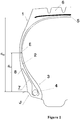
- the figure 1 shows only a half-view of a tire which is extended symmetrically with respect to the circumferential median plane, or equatorial plane, of a tire.
- the tire 1 is of dimension 12 R 22.5, has an aspect ratio H / L equal to 0.90.
- Said tire 1 comprises a radial carcass reinforcement 2 anchored in two beads 3.
- the carcass reinforcement 2 is wrapped at the top of the tire by a crown reinforcement 5, itself capped with a tread 6.
- the carcass reinforcement 2 formed of a single layer of metal cables, is wound in each of the beads 3 around a bead wire 4 and forms in each of the beads 3 an upturn of the carcass reinforcement layer 7 having a end 8.
- the carcass reinforcement 2 consists of reinforcing elements between two calendering layers whose modulus of elasticity under tension at 10% elongation is equal to 9.8 MPa.
- the reinforcing elements of the carcass reinforcement 2 are cables 19.18 whose elongation at break is equal to 2.5%.
- the carcass reinforcement cords of the tire 1 are cords with layers of structure 1 + 6 + 12, not wrapped, consisting of a central core formed of a wire, an intermediate layer formed of six wires and of an outer layer formed of twelve threads.
- the figure 1 illustrates the tire mounted on its nominal rim J; the axially outermost point E of the main part of the carcass reinforcement layer 2 is thus determined, the tire being inflated to its nominal pressure, for example by tomography.
- the figure 2 illustrates in an enlarged manner a schematic cross-sectional representation of a bead 3 of the tire in which there is a part of the carcass reinforcement layer 2 wound around a bead wire 4 to form an upturn 7 with one end 8.
- the distance d E between point E and point A is equal to 128 mm.
- the distance d R between point 8 and point A is equal to 90 mm.
- the ratio of the distance d R to the distance d E is equal to 70% and therefore between 45 and 90%.
- the radial distance d CJ between the axially outermost point of the main part of the carcass reinforcement layer and the radially outermost point of the nominal rim is equal to 108.2 mm.
- the radial distance d SJ between the axially outer end of the layer of reinforcing elements of the axially widest crown reinforcement and the radially outermost point of the nominal rim is equal to 206.7 mm.
- the ratio of the distance d CJ to the distance d SJ is equal to 52.3% and therefore less than 53%.
- the upturn 7 of the carcass reinforcement layer is coupled to the main part of the carcass reinforcement layer 2 from point C, such that the distance d C between point C and point A is equal to 37 mm.
- the ratio of the distance d C to the distance d R is equal to 41% and therefore between 30 and 55%.
- the upturn 7 of the carcass reinforcement layer is then decoupled from the main part of the carcass reinforcement layer 2 from point D, such that the distance d D between point D and point A is equal to 66 mm and such that the coupling length between point C and point D is equal to 29 mm and therefore between 25 and 40% of the distance d R.
- the coupling length is measured along the line passing through points C and D.
- the coupling thickness between the main part of the carcass reinforcement layer 2 and the upturn 7 of the carcass reinforcement layer is substantially constant and equal to 2.9 mm.
- the decoupling length between point D and point 8 is equal to 21 mm and therefore between 15 and 35% of the distance d R.
- the decoupling length is measured along the straight line passing through points D and 8.
- the upturn 7 of the carcass reinforcement layer is separated from the main part of the carcass reinforcement layer 2 by a first layer of polymeric mixture 9, having a radially outer end 10 at a distance d 10 from point A equal to 117 mm.
- the first layer of polymeric mixture 9 exhibits a modulus of elasticity under tension at 10% elongation equal to 7.8 MPa and therefore less than the modulus of elasticity under tension at 10% elongation of the calendering layers of the reinforcement. carcass 2.
- the first layer of polymeric mixture 9 is profiled so as to bear on the bead wire 4 and ensure the coupling and decoupling between the turning over of the carcass reinforcement layer 7 and the main part of the carcass reinforcement layer 2.
- the second layer of polymeric mixture 11 Axially outside of the upturn 7 of the carcass reinforcement layer is shown the second layer of polymeric mixture 11, the radially outer end 12 of which is radially inside the end 8 of the upturn 7 of the layer d carcass reinforcement.
- the radially inner end 13 of the second layer of polymeric mixture 11 is radially comprised between points A and B, respectively radially innermost and radially outermost of the circle circumscribed to the bead wire.
- the second layer of polymeric mixture 11 has an elastic modulus under tension at 10% elongation equal to 12.5 MPa and therefore greater than the modulus of elasticity under tension at 10% elongation of the first layer of polymeric mixture 9 which is equal to 7.8 MPa and less than 150% of the modulus of elasticity under tension at 10% elongation of the calendering layers of the carcass reinforcement 2 which is equal to 9.8 MPa.
- the third layer of polymeric mixture 14 has an elastic modulus under tension at 10% elongation equal to 7.1 MPa.
- the radially inner end 17 of the fourth polymeric blend layer 16 is radially inner to the end 15 of third polymeric blend layer 14.
- the fourth layer of polymeric mixture 16 has a modulus of elasticity under tension at 10% elongation equal to 3.1 MPa.
- the profile of the fourth layer of polymeric mixture 16 is such that said fourth layer of polymeric mixture 16 has a thickness , measured in the direction normal to the reinforcing elements of the carcass reinforcement 2 at the end 8 of the upturn 7, substantially constant and equal to 3.3 mm, over two radial lengths of approximately 5 mm from each of the two points located on either side of end 8 at distances from said end 8 equal to 2.5 mm corresponding to more than 2.5 times the diameter of the carcass reinforcement cables, the latter being equal to 0.9 mm.
- I 2 tires differ from I 1 tires by the use of a first layer of polymeric mixture whose modulus of elasticity under tension at 10% elongation is equal to 3.7 MPa and therefore less than 50% of that of calenders of the carcass reinforcement layer which is equal to 9.8 MPa.
- the reference tires R differ from the tires according to the invention by the presence of stiffeners and a more usual bead zone with in particular a distance between the end of the upturn of the carcass reinforcement layer and the radially innermost point of the bead.
- circle circumscribed to the bead wire equal to 37% of the distance between the axially outermost point of the main part of the carcass reinforcement layer and the radially innermost point of the circle circumscribed to the bead wire and a second layer of mixture polymer whose modulus of elasticity under tension at 10% elongation is equal to 3.7 MPa and less than that of the calenders of the carcass reinforcement layer which is equal to 9.8 MPa.
- Endurance tests were carried out by rolling two planed tires on top of each other with a regulated pressure of 8b, with nitrogen inflation and a load of 6786 daN at a speed of 30 km / h.
- the tests carried out lead, for the reference tires R, to performances establishing the base 100.
- the tests are stopped when a deterioration occurs in the bottom zone of the tire.
Description
La présente invention concerne un pneumatique, à armature de carcasse radiale et plus particulièrement un pneumatique destiné à équiper des véhicules portant de lourdes charges et roulant à vitesse soutenue, tels que, par exemple les camions, tracteurs, remorques ou bus routiers.The present invention relates to a tire with a radial carcass reinforcement and more particularly to a tire intended for fitting vehicles carrying heavy loads and traveling at sustained speed, such as, for example, trucks, tractors, trailers or road buses.
D'une manière générale dans les pneumatiques de type poids-lourds, l'armature de carcasse est ancrée de part et d'autre dans la zone du bourrelet et est surmontée radialement par une armature de sommet constituée d'au moins deux couches, superposées et formées de fils ou câbles parallèles dans chaque couche et croisés d'une couche à la suivante en faisant avec la direction circonférentielle des angles compris entre 10° et 45°. Lesdites couches de travail, formant l'armature de travail, peuvent encore être recouvertes d'au moins une couche dite de protection et formée d'éléments de renforcement avantageusement métalliques et extensibles, dits élastiques. Elle peut également comprendre une couche de fils ou câbles métalliques à faible extensibilité faisant avec la direction circonférentielle un angle compris entre 45° et 90°, cette nappe, dite de triangulation, étant radialement située entre l'armature de carcasse et la première nappe de sommet dite de travail, formées de fils ou câbles parallèles présentant des angles au plus égaux à 45° en valeur absolue. La nappe de triangulation forme avec au moins ladite nappe de travail une armature triangulée, qui présente, sous les différentes contraintes qu'elle subit, peu de déformations, la nappe de triangulation ayant pour rôle essentiel de reprendre les efforts de compression transversale dont est l'objet l'ensemble des éléments de renforcement dans la zone du sommet du pneumatique.In general, in heavy-duty type tires, the carcass reinforcement is anchored on both sides in the bead zone and is surmounted radially by a crown reinforcement made up of at least two superimposed layers. and formed of parallel wires or cables in each layer and crossed from one layer to the next making angles of between 10 ° and 45 ° with the circumferential direction. Said working layers, forming the working reinforcement, may also be covered with at least one so-called protective layer and formed from advantageously metallic and extensible reinforcing elements, called elastic. It may also comprise a layer of low extensibility metal wires or cables forming an angle of between 45 ° and 90 ° with the circumferential direction, this ply, called triangulation ply, being located radially between the carcass reinforcement and the first ply of so-called working top, formed of parallel wires or cables having angles at most equal to 45 ° in absolute value. The triangulation ply forms with at least said working ply a triangulated reinforcement, which presents, under the various stresses to which it is subjected, little deformation, the triangulation ply having the essential role of taking up the transverse compressive forces of which is the 'object all the reinforcement elements in the region of the crown of the tire.
Des câbles sont dits inextensibles lorsque lesdits câbles présentent sous une force de traction égale à 10% de la force de rupture un allongement relatif au plus égal à 0,2%.Cables are said to be inextensible when said cables have, under a tensile force equal to 10% of the breaking force, a relative elongation at most equal to 0.2%.
Des câbles sont dits élastiques lorsque lesdits câbles présentent sous une force de traction égale à la charge de rupture un allongement relatif au moins égal à 3% avec un module tangent maximum inférieur à 150 GPa.Cables are said to be elastic when said cables have, under a tensile force equal to the breaking load, a relative elongation at least equal to 3% with a maximum tangent modulus of less than 150 GPa.
Des éléments de renforcement circonférentiels sont des éléments de renforcement qui font avec la direction circonférentielle des angles compris dans l'intervalle + 2,5°, - 2,5° autour de 0°.Circumferential reinforcing elements are reinforcing elements which form angles with the circumferential direction in the range + 2.5 °, - 2.5 ° around 0 °.
La direction circonférentielle du pneumatique, ou direction longitudinale, est la direction correspondant à la périphérie du pneumatique et définie par la direction de roulement du pneumatique.The circumferential direction of the tire, or longitudinal direction, is the direction corresponding to the periphery of the tire and defined by the rolling direction of the tire.
La direction transversale ou axiale du pneumatique est parallèle à l'axe de rotation du pneumatique.The transverse or axial direction of the tire is parallel to the axis of rotation of the tire.
La direction radiale est une direction coupant l'axe de rotation du pneumatique et perpendiculaire à celui-ci.The radial direction is a direction intersecting the axis of rotation of the tire and perpendicular to the latter.
L'axe de rotation du pneumatique est l'axe autour duquel il tourne en utilisation normale.The axis of rotation of the tire is the axis around which it rotates in normal use.
Un plan radial ou méridien est un plan qui contient l'axe de rotation du pneumatique.A radial or meridian plane is a plane which contains the axis of rotation of the tire.
Le plan médian circonférentiel, ou plan équatorial, est un plan perpendiculaire à l'axe de rotation du pneu et qui divise le pneumatique en deux moitiés.The circumferential median plane, or equatorial plane, is a plane perpendicular to the axis of rotation of the tire and which divides the tire into two halves.
En ce qui concerne les fils ou câbles métalliques, les mesures de force à la rupture (charge maximale en N), de résistance à la rupture (en MPa), d'allongement à la rupture (allongement total en %) et de module (en GPa) sont effectuées en traction selon la norme ISO 6892 de 1984.With regard to metal wires or cables, the measurements of force at break (maximum load in N), resistance at break (in MPa), elongation at break (total elongation in%) and modulus ( in GPa) are carried out in tension according to the ISO 6892 standard of 1984.
En ce qui concerne les compositions de caoutchouc, les mesures de module sont effectuées en traction selon la norme AFNOR-NFT-46002 de septembre 1988 : on mesure en seconde élongation (i.e., après un cycle d'accommodation) le module sécant nominal (ou contrainte apparente, en MPa) à 10% d'allongement (conditions normales de température et d'hygrométrie selon la norme AFNOR-NFT-40101 de décembre 1979).As regards the rubber compositions, the modulus measurements are carried out in tension according to the AFNOR-NFT-46002 standard of September 1988: the nominal secant modulus (or apparent stress, in MPa) at 10% elongation (normal temperature and humidity conditions according to the AFNOR-NFT-40101 standard of December 1979).
De tels pneumatiques comportent encore usuellement au niveau des bourrelets une ou plusieurs couches d'éléments de renforcement appelés raidisseurs. Ces couches sont le plus souvent constituées d'éléments de renforcement orientés par rapport à la direction circonférentielle d'un angle inférieur à 45°, et le plus souvent inférieur à 25°. Ces couches d'éléments de renforcements ont notamment pour fonction de limiter les déplacements longitudinaux des matériaux constitutifs du bourrelet par rapport à la jante de la roue pour limiter une usure prématurée dudit bourrelet. Elles permettent également de limiter la déformation permanente du bourrelet sur le crochet de jante, due au phénomène de fluage dynamique des matériaux élastomériques. Cette déformation du bourrelet peut empêcher le rechapage des pneumatiques lorsqu'elle est excessive. Elles contribuent encore à la protection des zones basses du pneumatique contre les agressions subies lors du montage et du démontage des pneumatiques sur les jantes.Such tires also usually include, at the level of the beads, one or more layers of reinforcing elements called stiffeners. These layers are most often made up of reinforcing elements oriented relative to the circumferential direction at an angle less than 45 °, and most often less than 25 °. These layers of reinforcing elements have the particular function of limiting the longitudinal displacements of the materials constituting the bead relative to the rim of the wheel in order to limit premature wear of said bead. They also make it possible to limit the permanent deformation of the bead on the rim hook, due to the phenomenon of dynamic creep of the elastomeric materials. This deformation of the bead can prevent retreading of the tires when it is excessive. They further contribute to the protection of the lower areas of the tire against attacks suffered during the fitting and removal of the tires on the rims.
Par ailleurs, dans le cas d'ancrage de l'armature de carcasse réalisé autour d'une tringle, qui consiste à enrouler au moins en partie l'armature de carcasse autour d'une tringle dans chacun des bourrelets en formant un retournement s'étendant plus ou moins haut dans le flanc, les couches d'éléments de renforcement ou raidisseur permettent encore d'éviter ou de retarder le déroulement de l'armature de carcasse lors d'échauffements accidentels et excessifs de la jante.Moreover, in the case of anchoring of the carcass reinforcement produced around a bead wire, which consists in at least partially winding the carcass reinforcement around a bead wire in each of the beads, forming an upturn s' extending more or less high in the sidewall, the layers of reinforcing or stiffening elements also make it possible to prevent or delay the unwinding of the carcass reinforcement during accidental and excessive heating of the rim.
Ces couches d'éléments de renforcement ou raidisseurs sont le plus souvent disposées axialement à l'extérieur du retournement de l'armature de carcasse et s'étendent sur une hauteur dans le flanc supérieure à celle du retournement notamment pour couvrir les extrémités libres des éléments de renforcement dudit retournement.These layers of reinforcing or stiffening elements are most often arranged axially outside the upturn of the carcass reinforcement and extend over a height in the sidewall greater than that of the upturn, in particular to cover the free ends of the elements. reinforcement of said reversal.
De telles conceptions de pneumatiques sont par exemples décrites dans les documents
La présence de ces couches d'éléments de renforcement ou raidisseurs complexifient la conception de ces zones des bourrelets du pneumatique. La présence d'une couche supplémentaire d'une part et son agencement par rapport notamment au retournement de l'armature de carcasse et à la tringle d'autre part conduisent à une conception nécessitant des mélanges caoutchouteux pour séparer les extrémités de couches et assurer le positionnement souhaité des différentes extrémités.The presence of these layers of reinforcing or stiffening elements complicates the design of these areas of the tire beads. The presence of an additional layer on the one hand and its arrangement with respect in particular to the upturn of the carcass reinforcement and to the bead wire on the other hand lead to a design requiring rubber mixes to separate the ends of the layers and ensure the desired positioning of the different ends.
Par ailleurs, le document
Les inventeurs se sont ainsi donnés pour mission de fournir des pneumatiques pour véhicules "Poids-Lourds", dont les performances d'endurance notamment l'endurance des zones des bourrelets sont conservées et dont la conception est simplifiée et avantageusement dont la masse globale du pneumatique est diminuée.The inventors have thus set themselves the task of supplying tires for "Heavy Duty" vehicles, the endurance performance of which, in particular the endurance of the areas of the beads, is preserved and the design of which is simplified and advantageously of which the overall mass of the tire. is diminished.
Ce but a été atteint selon l'invention par un pneumatique destiné à être monté sur une jante creuse (15 ° drop centre), comprenant une armature de carcasse radiale, constituée d'une unique couche d'armature de carcasse formée d'éléments de renforcement insérés entre deux couches de calandrage de mélange polymérique, ledit pneumatique comprenant une armature de sommet, elle-même coiffée radialement d'une bande de roulement, ladite bande de roulement étant réunie à deux bourrelets par l'intermédiaire de deux flancs, la couche d'éléments de renforcement de l'armature de carcasse étant ancrée dans chacun des bourrelets par retournement autour d'une tringle pour former une partie principale de la couche d'armature de carcasse s'étendant d'une tringle à l'autre et un retournement de la couche d'armature de carcasse dans chacun des bourrelets, ledit retournement de la couche d'armature de carcasse étant séparé de la partie principale de la couche d'armature de carcasse par une première couche de mélange polymérique s'étendant radialement depuis la tringle jusqu'au moins l'extrémité du retournement de la couche d'armature de carcasse et ledit retournement de la couche d'armature de carcasse étant axialement vers l'extérieur au contact d'une deuxième couche de mélange polymérique, elle-même au moins au contact d'une troisième couche de mélange polymérique formant la surface extérieur du pneumatique dans la zone du bourrelet, ladite troisième couche de mélange polymérique étant destinée notamment à venir au contact de la jante, ladite troisième couche de mélange polymérique étant radialement vers l'extérieur au contact d'une quatrième couche de mélange polymérique formant la surface extérieure d'un flanc, et conformément à l'invention, dans une coupe méridienne dudit pneumatique,
- l'extrémité radialement extérieure de la première couche de mélange polymérique est radialement extérieure à l'extrémité du retournement de la couche d'armature de carcasse,
- l'extrémité du retournement de la couche d'armature de carcasse est radialement extérieure à l'extrémité radialement extérieure de la deuxième couche de mélange polymérique,
- l'extrémité radialement extérieure de la deuxième couche de mélange polymérique est radialement extérieure à l'extrémité radialement extérieure de la troisième couche de mélange polymérique,
- la distance entre l'extrémité du retournement de la couche d'armature de carcasse et le point radialement le plus intérieur du cercle circonscrit à la tringle est comprise entre 45 et 90% de la distance entre le point axialement le plus extérieur de la partie principale de la couche d'armature de carcasse et le point radialement le plus intérieur du cercle circonscrit à la tringle,
- le retournement de la couche d'armature de carcasse et la partie principale de la couche d'armature de carcasse sont les seules couches d'éléments de renforcement dont l'allongement à rupture est inférieur à 6 % présentes dans une zone du flanc constituant au moins 90% de la surface du flanc comprise radialement entre l'extrémité du retournement de la couche d'armature de carcasse et le point radialement le plus extérieur du cercle circonscrit à la tringle, et
- radialement vers l'extérieur, à partir d'un point C du retournement de la couche d'armature de carcasse situé à une distance du point radialement le plus intérieur du cercle circonscrit à la tringle comprise entre 30 et 55% de la distance entre l'extrémité du retournement de la couche d'armature de carcasse et le point radialement le plus intérieur du cercle circonscrit à la tringle, le retournement de la couche d'armature de carcasse et la partie principale de la couche d'armature de carcasse sont couplés sur une longueur comprise entre 15 et 65% de la distance entre l'extrémité du retournement de la couche d'armature de carcasse et le point radialement le plus intérieur du cercle circonscrit à la tringle, pour être ensuite découplés par la première couche de mélange polymérique jusqu'à l'extrémité du retournement de la couche d'armature de carcasse sur une longueur comprise entre 5 et 40 % de la distance entre l'extrémité du retournement de la couche d'armature de carcasse et le point radialement le plus intérieur du cercle circonscrit à la tringle.
- the radially outer end of the first layer of polymeric mixture is radially outer to the end of the upturn of the carcass reinforcement layer,
- the end of the upturn of the carcass reinforcement layer is radially outside the radially outside end of the second layer of polymeric mixture,
- the radially outer end of the second layer of polymeric mixture is radially outer to the radially outer end of the third layer of polymeric mixture,
- the distance between the end of the upturn of the carcass reinforcement layer and the radially innermost point of the circle circumscribing the bead wire is between 45 and 90% of the distance between the axially outermost point of the main part of the carcass reinforcement layer and the radially innermost point of the circle circumscribing the bead wire,
- the turning over of the carcass reinforcement layer and the main part of the carcass reinforcement layer are the only layers of reinforcing elements with an elongation at break of less than 6% present in an area of the sidewall constituting the at least 90% of the surface area of the sidewall lying radially between the end of the upturn of the carcass reinforcement layer and the radially outermost point of the circle circumscribing the bead wire, and
- radially outwards, from a point C of the upturn of the carcass reinforcement layer located at a distance from the radially innermost point of the circle circumscribed to the bead wire between 30 and 55% of the distance between l 'end of the carcass reinforcement layer upturn and the radially innermost point of the bead wire circle, the carcass reinforcement layer upturn and the main part of the carcass reinforcement layer are coupled over a length between 15 and 65% of the distance between the end of the upturn of the carcass reinforcement layer and the radially innermost point of the circle circumscribing the bead wire, to be then decoupled by the first layer of mixture polymeric to the end of the carcass reinforcement layer upturn over a length of 5 to 40% of the distance between the end of the carcass reinforcement layer upturn and the point t radially the innermost of the circle circumscribed to the rod.
Au sens de l'invention, une jante creuse (15° drop center) ou jante à seat coincé est une jante monobloc, telle que définie dans l'ETRTO, dont les sièges destinés à recevoir les bourrelets du pneumatique présentent une forme tronconique, l'angle formé avec la direction axiale étant sensiblement équivalant à 15°. Ces sièges sont par ailleurs prolongés par des crochets de jante de hauteur réduite par rapport à des crochets de jantes à bases plates dont les sièges de jante présentent des formes sensiblement cylindriques.For the purposes of the invention, a hollow rim (15 ° drop center) or stuck seat rim is a one-piece rim, as defined in ETRTO, the seats of which intended to receive the beads of the tire have a frustoconical shape, the the angle formed with the axial direction being substantially equivalent to 15 °. These seats are also extended by rim hooks of reduced height compared to rim hooks with flat bases, the rim seats of which have substantially cylindrical shapes.
La position du point axialement le plus extérieur de la partie principale de l'armature de carcasse est déterminée sur un pneumatique monté et gonflé selon les conditions nominales. Cette détermination peut être réalisée par exemple selon une technique de tomographie.The position of the axially outermost point of the main part of the carcass reinforcement is determined on a tire mounted and inflated according to nominal conditions. This determination can be carried out, for example, using a tomography technique.
Les positions des points radialement le plus intérieur et radialement le plus extérieur du cercle circonscrit à la tringle peuvent également être déterminées selon une technique de tomographie ou bien sont déterminées sur une coupe d'un pneumatique, dont l'écartement des bourrelets est le même que lorsque le pneumatique est monté sur la jante de montage préconisée par l'ETRTO, celui-ci étant donc ni monté ni gonflé.The positions of the radially innermost and radially outermost points of the circle circumscribed to the bead wire can also be determined according to a tomography technique or else are determined on a section of a tire, the spacing of the beads of which is the same as when the tire is mounted on the mounting rim recommended by ETRTO, the latter therefore being neither mounted nor inflated.
La distance entre le point axialement le plus extérieur de la partie principale de la couche d'armature de carcasse et le point radialement le plus intérieur du cercle circonscrit à la tringle est mesurée sur un pneumatique monté et gonflé selon les conditions nominales. Cette mesure peut être réalisée par exemple selon une technique de tomographie.The distance between the axially outermost point of the main part of the carcass reinforcement layer and the radially innermost point of the circle circumscribing the bead wire is measured on a tire mounted and inflated according to nominal conditions. This measurement can be carried out, for example, using a tomography technique.
Les autres distances, notamment mesurées depuis le point radialement le plus intérieur du cercle circonscrit à la tringle, peuvent également être mesurées selon une technique de tomographie ou bien sont mesurées sur une coupe d'un pneumatique, dont l'écartement des bourrelets est le même que lorsque le pneumatique est monté sur la jante de montage préconisée par l'ETRTO, celui-ci étant donc ni monté ni gonflé.The other distances, in particular measured from the radially innermost point of the circle circumscribed to the bead wire, can also be measured using a tomography technique or else are measured on a section of a tire, the spacing of the beads of which is the same. only when the tire is mounted on the mounting rim recommended by the ETRTO, the latter therefore being neither mounted nor inflated.
Au sens de l'invention, la partie principale de la couche d'armature de carcasse et le retournement de la couche d'armature de carcasse sont dits couplés si les éléments de renforcement respectifs la partie principale de la couche d'armature de carcasse et du retournement de la couche d'armature de carcasse sont séparés par une épaisseur de mélange caoutchouteux sensiblement constante et d'au plus 5 mm sur une longueur supérieure à 15% de la distance entre l'extrémité du retournement de la couche d'armature de carcasse et le point radialement le plus intérieur du cercle circonscrit à la tringle. L'épaisseur de mélange caoutchouteux séparant les éléments de renforcement respectifs de la partie principale de la couche d'armature de carcasse et du retournement de la couche d'armature de carcasse est mesurée selon la direction normale aux éléments de renforcement de l'armature de carcasse. Avantageusement selon l'invention, les éléments de renforcement respectifs de la partie principale de la couche d'armature de carcasse et du retournement de la couche d'armature de carcasse sont séparés par une épaisseur de mélange caoutchouteux sensiblement constante d'au plus 3.5 mm et de préférence ils sont séparés par une épaisseur de mélange caoutchouteux sensiblement constante d'au moins 0.8 mm et de préférence encore par une épaisseur de mélange caoutchouteux sensiblement constante d'au moins 2.5 mm.Within the meaning of the invention, the main part of the carcass reinforcement layer and the turning over of the carcass reinforcement layer are said to be coupled if the respective reinforcing elements the main part of the carcass reinforcement layer and of the overturning of the carcass reinforcement layer are separated by a thickness of rubber mixture substantially constant and at most 5 mm over a length greater than 15% of the distance between the end of the upturn of the carcass reinforcement layer and the radially innermost point of the circle circumscribing the bead wire. The thickness of the rubber mixture separating the respective reinforcing elements from the main part of the carcass reinforcement layer and from the upturn of the carcass reinforcement layer is measured in the direction normal to the reinforcing elements of the carcass reinforcement. carcass. Advantageously according to the invention, the respective reinforcing elements of the main part of the carcass reinforcement layer and of the upturn of the carcass reinforcement layer are separated by a substantially constant rubber mixture thickness of at most 3.5 mm. and preferably they are separated by a substantially constant rubber mixture thickness of at least 0.8 mm and more preferably by a substantially constant rubber mixture thickness of at least 2.5 mm.
Au sens de l'invention, une épaisseur de mélange caoutchouteux sensiblement constante séparant les éléments de renforcement respectifs de la partie principale de la couche d'armature de carcasse et du retournement de la couche d'armature de carcasse est une épaisseur qui ne varie pas de plus de 0.5 mm. Les variations d'épaisseur ne sont alors dues qu'aux phénomènes de fluage lors de la fabrication et de la cuisson du pneumatique.For the purposes of the invention, a substantially constant thickness of rubber mixture separating the respective reinforcing elements from the main part of the carcass reinforcement layer and from the upturn of the carcass reinforcement layer is a thickness which does not vary more than 0.5 mm. The variations in thickness are then due only to creep phenomena during the manufacture and curing of the tire.
Au sens de l'invention, la première couche de mélange polymérique peut être constituée de plusieurs mélanges polymériques dont les propriétés de rigidité sont sensiblement identiques et plus spécifiquement dont les modules d'élasticité sous tension à 10 % d'allongement sont sensiblement identiques. Au sens de l'invention, l'expression « sensiblement identiques » doit être comprise comme signifiant égaux aux incertitudes de mesures près. Pour diverses raisons, de telles couches séparant le retournement de l'armature de carcasse de l'armature de carcasse ont déjà été décrites comme étant constituées de plusieurs couches radialement superposées dont les propriétés de rigidités diffèrent; ce type de réalisation n'est pas adapté au cas de l'invention au risque de nuire aux performances d'endurance du pneumatique.For the purposes of the invention, the first layer of polymeric mixture may consist of several polymeric mixtures whose rigidity properties are substantially identical and more specifically whose moduli of elasticity under tension at 10% elongation are substantially identical. For the purposes of the invention, the expression “substantially identical” should be understood as meaning equal to the uncertainties of measurements. For various reasons, such layers separating the upturn of the carcass reinforcement from the carcass reinforcement have already been described as being made up of several radially superimposed layers, the stiffness properties of which differ; this type of embodiment is not suitable for the case of the invention at the risk of adversely affecting the endurance performance of the tire.
Au sens de l'invention, la partie principale de la couche d'armature de carcasse et le retournement la couche d'armature de carcasse sont dits découplés si, radialement à l'extérieur de la zone de couplage, l'épaisseur de mélange caoutchouteux séparant les éléments de renforcement respectifs de la partie principale de la couche d'armature de carcasse et du retournement de la couche d'armature de carcasse est supérieure à celle de la zone de couplage. Les éléments de renforcement respectifs de la partie principale de la couche d'armature de carcasse et du retournement de la couche d'armature de carcasse sont alors avantageusement séparés par une épaisseur de mélange caoutchouteux comprise entre 3 et 8 mm, ladite épaisseur de mélange caoutchouteux étant mesurée selon la direction normale aux éléments de renforcement de la partie principale de la couche d'armature de carcasse entre les éléments de renforcement respectifs de la partie principale de la couche d'armature de carcasse et du retournement de la couche d'armature de carcasse. De préférence selon l'invention, dans la zone de découplage, les éléments de renforcement respectifs de la partie principale de la couche d'armature de carcasse et du retournement de la couche d'armature de carcasse sont séparés d'au plus 6 mm et de préférence ils sont séparés d'au moins 4 mm.For the purposes of the invention, the main part of the carcass reinforcement layer and the upturning of the carcass reinforcement layer are said to be decoupled if, radially outside the coupling zone, the thickness of the rubber mixture separating the Respective reinforcing elements of the main part of the carcass reinforcement layer and the upturn of the carcass reinforcement layer is greater than that of the coupling area. The respective reinforcing elements of the main part of the carcass reinforcement layer and of the upturn of the carcass reinforcement layer are then advantageously separated by a thickness of rubber mixture of between 3 and 8 mm, said thickness of rubber mixture being measured in the direction normal to the reinforcing elements of the main part of the carcass reinforcement layer between the respective reinforcing elements of the main part of the carcass reinforcement layer and the upturn of the carcass reinforcement layer carcass. Preferably according to the invention, in the decoupling zone, the respective reinforcing elements of the main part of the carcass reinforcement layer and of the upturn of the carcass reinforcement layer are separated by at most 6 mm and preferably they are separated by at least 4 mm.
Selon un mode de réalisation avantageux de l'invention, la zone de découplage peut être constituée d'une première partie, dite de transition, prolongeant la zone de couplage dans laquelle l'épaisseur de mélange caoutchouteux séparant les éléments de renforcement respectifs de la partie principale de la couche d'armature de carcasse et du retournement de la couche d'armature de carcasse augmente et d'une deuxième partie radialement la plus extérieure dans laquelle l'épaisseur de mélange caoutchouteux séparant les éléments de renforcement respectifs de la partie principale de la couche d'armature de carcasse et du retournement de la couche d'armature de carcasse est sensiblement constante.According to an advantageous embodiment of the invention, the decoupling zone may consist of a first part, called a transition part, extending the coupling zone in which the thickness of the rubber mixture separating the respective reinforcing elements from the part. main part of the carcass reinforcement layer and the upturn of the carcass reinforcement layer increases and a second radially outermost part in which the thickness of rubber mix separating the respective reinforcing elements from the main part of the carcass reinforcement layer and the overturning of the carcass reinforcement layer is substantially constant.
Selon un mode de réalisation préféré de l'invention, l'armature de sommet comportant au moins une couche d'éléments de renforcement, le ratio de la distance radiale entre le point axialement le plus extérieur de la partie principale de la couche d'armature de carcasse et le point radialement le plus extérieur de la jante nominale, c'est-à-dire le point radialement le plus extérieur du crochet de jante, sur la distance radiale entre l'extrémité axialement extérieure de la couche d'éléments de renforcement de l'armature sommet axialement la plus large et le point radialement le plus extérieur de la jante nominale est inférieur ou égal à 55 %.According to a preferred embodiment of the invention, the crown reinforcement comprising at least one layer of reinforcing elements, the ratio of the radial distance between the axially outermost point of the main part of the reinforcement layer carcass and the radially outermost point of the nominal rim, i.e. the radially outermost point of the rim hook, on the radial distance between the axially outer end of the layer of reinforcing elements of the axially widest crown reinforcement and the radially outermost point of the nominal rim is less than or equal to 55%.
La distance radiale entre le point axialement le plus extérieur de la partie principale de la couche d'armature de carcasse et le point radialement le plus extérieur de la jante nominale est mesurée sur un pneumatique monté et gonflé selon les conditions nominales. Cette mesure peut être réalisée par exemple selon une technique de tomographie.The radial distance between the axially outermost point of the main part of the carcass reinforcement layer and the radially outermost point of the nominal rim is measured on a tire mounted and inflated under nominal conditions. This measurement can be carried out, for example, using a tomography technique.
La distance radiale entre l'extrémité axialement extérieure de la couche d'éléments de renforcement de l'armature sommet axialement la plus large et le point radialement le plus extérieur de la jante nominale peut également être mesurée selon une technique de tomographie, le pneumatique étant monté et gonflé selon les conditions nominales.The radial distance between the axially outer end of the layer of reinforcing elements of the axially widest crown reinforcement and the radially outermost point of the nominal rim can also be measured using a tomography technique, the tire being mounted and inflated to nominal conditions.
De préférence encore selon l'invention, le ratio de la distance radiale entre le point axialement le plus extérieur de la partie principale de la couche d'armature de carcasse et le point radialement le plus extérieur de la jante nominale sur la distance radiale entre l'extrémité axialement extérieure de la couche d'éléments de renforcement de l'armature sommet axialement la plus large et le point radialement le plus extérieur de la jante nominale est inférieur à 53 %.Also preferably according to the invention, the ratio of the radial distance between the axially outermost point of the main part of the carcass reinforcement layer and the radially outermost point of the nominal rim over the radial distance between l The axially outer end of the layer of reinforcing elements of the axially widest crown reinforcement and the radially outermost point of the nominal rim is less than 53%.
Les essais ont montré que les pneumatiques ainsi réalisés selon l'invention et dont la masse est inférieure à celle de pneumatiques de conception plus usuelle, comportant par exemple des couches d'éléments de renforcement supplémentaires de type raidisseurs, présentent des performances en termes d'endurance, et notamment en termes d'endurance des zones des bourrelets, au moins aussi bonnes que celles desdits pneumatiques de conception plus usuelle, voire supérieures.The tests have shown that the tires thus produced according to the invention and whose mass is less than that of tires of more usual design, comprising for example layers of additional reinforcing elements of the stiffening type, exhibit performance in terms of endurance, and in particular in terms of endurance of the areas of the beads, at least as good as those of said tires of more usual design, or even better.
Ces résultats sont d'autant plus surprenants que les conceptions plus usuelles de ce type de pneumatiques comportent un retournement de la couche d'armature de carcasse tel que la distance entre l'extrémité du retournement de la couche d'armature de carcasse et le point radialement le plus intérieur du cercle circonscrit à la tringle est inférieure à 45 % de la distance entre le point axialement le plus extérieur de la partie principale de la couche d'armature de carcasse et le point radialement le plus intérieur du cercle circonscrit à la tringle pour notamment améliorer les performances du pneumatique en termes d'endurance. En effet, il est usuel de concevoir des pneumatiques avec un retournement de la couche d'armature de carcasse de longueur réduite pour augmenter la distance entre le retournement de la couche d'armature de carcasse et la partie principale de la couche d'armature de carcasse, et ainsi limiter au mieux les contraintes de cisaillement qui s'initient entre la partie principale de la couche d'armature de carasse et son retournement notamment du fait des phénomènes de déradialisation qui apparaissent lors du roulage du pneumatique.These results are all the more surprising since the more usual designs of this type of tire include an upturn of the carcass reinforcement layer such that the distance between the end of the upturn of the carcass reinforcement layer and the point radially innermost circle circumscribed to the bead wire is less than 45% of the distance between the axially outermost point of the main part of the carcass reinforcement layer and the radially innermost point of the circle circumscribed to the bead wire in particular to improve the performance of the tire in terms of endurance. In fact, it is usual to design tires with an inversion of the layer of carcass reinforcement of reduced length to increase the distance between the turning over of the carcass reinforcement layer and the main part of the carcass reinforcement layer, and thus as far as possible limit the shear stresses which are initiated between the main part of the shell reinforcement layer and its turning over, in particular due to the deradialization phenomena which appear when the tire is rolling.
Il est également usuel dans la conception des pneumatiques dont la couche d'armature de carcasse présente un retournement, destinés notamment à être montés sur une jante à seat coincé et à équiper des véhicules portant de lourdes charges, d'éviter un rapprochement et donc d'autant plus un couplage du retournement de la couche d'armature de carcasse avec la partie principale de la couche d'armature de carcasse de façon à prévenir tout risque de cisaillement entre la partie principale de la couche d'armature de carcasse et son retournement qui vient pénaliser la première couche de mélange polymérique qui les sépare.It is also customary in the design of tires the carcass reinforcement layer of which has an upturn, intended in particular to be mounted on a stuck seat rim and to equip vehicles carrying heavy loads, to avoid coming together and therefore '' even more a coupling of the upturn of the carcass reinforcement layer with the main part of the carcass reinforcement layer so as to prevent any risk of shearing between the main part of the carcass reinforcement layer and its upturn which penalizes the first layer of polymeric mixture which separates them.
Les inventeurs ont ainsi su mettre en évidence que les pneumatiques réalisés conformément à l'invention et qui présentent notamment un retournement de la couche d'armature carcasse avec une longueur supérieure aux conceptions plus usuelles, un couplage du retournement de la couche d'armature de carasse avec la partie principale de la couche d'armature carcasse suivi d'un découplage dudit retournement de la couche d'armature de carasse et de la partie principale de la couche d'armature de carcasse, associés aux dimensionnements et positionnement relatifs des différents éléments constitutifs de la zone du bourrelet du pneumatique, permettent d'alléger le pneumatique et contre toute attente de conserver des propriétés en termes d'endurance satisfaisantes, voire de les améliorer.The inventors have thus been able to demonstrate that the tires produced in accordance with the invention and which in particular have an upturn of the carcass reinforcement layer with a length greater than the more usual designs, a coupling of the upturn of the reinforcement layer of shell with the main part of the carcass reinforcement layer followed by decoupling of said reversal of the shell reinforcement layer and the main part of the carcass reinforcement layer, associated with the relative dimensions and positioning of the various elements constituting the bead zone of the tire, make it possible to lighten the tire and, against all expectations, to retain satisfactory endurance properties, or even to improve them.
Le découplage entre le retournement de la couche d'armature de carasse et la partie principale de la couche d'armature de carcasse qui suit la zone de couplage est obtenu par une augmentation de l'épaisseur de la première couche de mélange polymérique. Ce découplage permet de venir compenser la diminution de la tension dans les éléments de renforcement de l'armature de carcasse lorsque l'on s'approche de l'extrémité de son retournement pour absorber les contraintes de cisaillement entre la partie principale de la couche d'armature de carcasse et son retournement.The decoupling between the inversion of the shell reinforcement layer and the main part of the carcass reinforcement layer which follows the coupling zone is obtained by increasing the thickness of the first layer of polymer mixture. This decoupling makes it possible to compensate for the decrease in tension in the reinforcing elements of the carcass reinforcement when approaching the end of its upturn to absorb the shear stresses between the main part of the layer of carcass reinforcement and its turning.
Avantageusement selon l'invention, la longueur de découplage est comprise entre 15 et 35% de la distance entre l'extrémité du retournement de la couche d'armature de carcasse et le point radialement le plus intérieur du cercle circonscrit à la tringle.Advantageously according to the invention, the decoupling length is between 15 and 35% of the distance between the end of the upturn of the carcass reinforcement layer and the radially innermost point of the circle circumscribed to the bead wire.
De préférence selon l'invention, le retournement de la couche d'armature de carcasse et la partie principale de la couche d'armature de carcasse sont couplés sur une longueur comprise entre 25 et 40% de la distance entre l'extrémité du retournement de la couche d'armature de carcasse et le point radialement le plus intérieur du cercle circonscrit à la tringle.Preferably according to the invention, the upturn of the carcass reinforcement layer and the main part of the carcass reinforcement layer are coupled over a length of between 25 and 40% of the distance between the end of the carcass reinforcement. the carcass reinforcement layer and the radially innermost point of the circle circumscribing the bead wire.
Avantageusement selon l'invention, l'extrémité radialement intérieure de la deuxième couche de mélange polymérique est radialement comprise entre le point radialement le plus extérieur du cercle circonscrit à la tringle et le point radialement le plus intérieur du cercle circonscrit à la tringle. Ce positionnement est déterminé sur une coupe d'un pneumatique, dont l'écartement des bourrelets est le même que lorsque le pneumatique est monté sur la jante de montage préconisée par l'ETRTO, celui-ci étant donc ni monté ni gonflé.Advantageously according to the invention, the radially inner end of the second layer of polymeric mixture is radially comprised between the radially outermost point of the circle circumscribed to the rod and the radially innermost point of the circle circumscribed to the rod. This positioning is determined on a section of a tire, the spacing of the beads of which is the same as when the tire is mounted on the mounting rim recommended by ETRTO, the latter therefore being neither mounted nor inflated.
Selon un mode de réalisation préféré de l'invention, le module d'élasticité sous tension à 10 % d'allongement des couches de calandrage de la couche d'armature de carcasse est compris entre 4 et 16 MPa et de préférence entre 8 et 12 MPa. Ces valeurs permettent notamment de définir le compromis souhaité entre les performances d'endurance du pneumatique et ses performances en termes de résistance au roulement.According to a preferred embodiment of the invention, the modulus of elasticity under tension at 10% elongation of the calendering layers of the carcass reinforcement layer is between 4 and 16 MPa and preferably between 8 and 12 MPa. These values make it possible in particular to define the desired compromise between the endurance performance of the tire and its performance in terms of rolling resistance.
De préférence selon l'invention, le module d'élasticité sous tension à 10 % d'allongement de la première couche de mélange polymérique est inférieur ou égal au module d'élasticité sous tension à 10 % d'allongement du calandrage de la couche d'armature de carcasse. Ce choix permet notamment de concentrer les efforts de cisaillement au sein de la première couche de mélange polymérique.Preferably according to the invention, the modulus of elasticity under tension at 10% elongation of the first layer of polymeric mixture is less than or equal to the modulus of elasticity under tension at 10% elongation of the calendering of the layer d. carcass reinforcement. This choice makes it possible in particular to concentrate the shearing forces within the first layer of polymeric mixture.
De préférence encore selon l'invention, le module d'élasticité sous tension à 10 % d'allongement de la première couche de mélange polymérique est supérieur à 50% du module d'élasticité sous tension à 10 % d'allongement du calandrage de la couche d'armature de carcasse et de préférence est supérieur à 70 % du module d'élasticité sous tension à 10 % d'allongement du calandrage de la couche d'armature de carcasse. Ce choix permet de maintenir les efforts de cisaillement au sein de la première couche de mélange polymérique tout en assurant de bonnes performances d'endurance.More preferably still according to the invention, the modulus of elasticity under tension at 10% elongation of the first layer of polymeric mixture is greater than 50% of the modulus of elasticity under tension at 10% elongation of the calendering of the layer carcass reinforcement and preferably is greater than 70% of the modulus of elasticity under tension at 10% elongation of the calendering of the carcass reinforcement layer. This choice makes it possible to maintain the shear forces within the first layer of polymeric mixture while ensuring good endurance performance.
Avantageusement selon l'invention, le module d'élasticité sous tension à 10 % d'allongement de la deuxième couche de mélange polymérique est supérieur au module d'élasticité sous tension à 10 % d'allongement de la première couche de mélange polymérique et de préférence strictement inférieur à 25 MPa ; il est avantageusement encore inférieur à 150% du module d'élasticité sous tension à 10 % d'allongement du calandrage de la couche d'armature de carcasse. Selon cette réalisation avantageuse de l'invention, la deuxième couche de mélange polymérique confère suffisamment de rigidité pour assurer une bonne tenue en endurance du pneumatique lors des appuis sur les crochets de jante tout en assurant des performances en termes de résistance au roulement satisfaisantes.Advantageously according to the invention, the modulus of elasticity under tension at 10% elongation of the second layer of polymeric mixture is greater than the modulus of elasticity under tension at 10% elongation of the first layer of polymeric mixture and of preferably strictly less than 25 MPa; it is advantageously still less than 150% of the modulus of elasticity under tension at 10% elongation of the calendering of the carcass reinforcement layer. According to this advantageous embodiment of the invention, the second layer of polymeric mixture confers sufficient rigidity to ensure good endurance behavior of the tire when pressing on the rim hooks while ensuring satisfactory performance in terms of rolling resistance.
Selon un mode de réalisation préféré de l'invention, pour favoriser le compromis entre les performances d'endurance et de résistance au roulement, le module d'élasticité sous tension à 10 % d'allongement de la première couche de mélange polymérique est supérieur ou égal au module d'élasticité sous tension à 10 % d'allongement de la troisième couche de mélange polymérique qui est lui-même supérieur ou égal au module d'élasticité sous tension à 10 % d'allongement de la quatrième couche de mélange polymérique.According to a preferred embodiment of the invention, to promote the compromise between endurance performance and rolling resistance, the modulus of elasticity under tension at 10% elongation of the first layer of polymeric mixture is greater than or equal to the modulus of elasticity under tension at 10% elongation of the third layer of polymeric blend which is itself greater than or equal to the modulus of elasticity under 10% elongation of the fourth layer of polymeric blend.
Selon un mode préféré de réalisation de l'invention, dans tout plan méridien, sur une longueur du retournement de la couche d'armature de carcasse délimitée radialement entre l'extrémité dudit retournement et un point situé à une distance du point radialement le plus intérieur du cercle circonscrit à la tringle égale à 65% de la distance entre l'extrémité du retournement de la couche d'armature de carcasse et le point radialement le plus intérieur du cercle circonscrit à la tringle, tout point du retournement de la couche d'armature de carcasse est à une distance de la surface extérieure du pneumatique inférieure à 10 mm. De préférence encore, tout point du retournement de la couche d'armature de carcasse est à une distance de la surface extérieure du pneumatique inférieure à 10 mm sur une longueur du retournement de la couche d'armature de carcasse délimitée radialement entre l'extrémité dudit retournement et un point situé à une distance du point radialement le plus intérieur du cercle circonscrit à la tringle égale à 50% de la distance entre l'extrémité du retournement de la couche d'armature de carcasse et le point radialement le plus intérieur du cercle circonscrit à la tringle.According to a preferred embodiment of the invention, in any meridian plane, over a length of the upturn of the carcass reinforcement layer delimited radially between the end of said upturn and a point located at a distance from the radially innermost point of the circle circumscribed to the bead wire equal to 65% of the distance between the end of the upturn of the carcass reinforcement layer and the radially innermost point of the circle circumscribed to the bead wire, any point of the upturn of the layer of carcass reinforcement is at a distance from the outer surface of the tire of less than 10 mm. More preferably, any point of the upturn of the carcass reinforcement layer is at a distance from the outer surface of the tire less than 10 mm over a length of the upturn of the defined carcass reinforcement layer. radially between the end of said upturn and a point located at a distance from the radially innermost point of the circle circumscribing the bead wire equal to 50% of the distance between the end of the upturn of the carcass reinforcement layer and the point radially the innermost of the circle circumscribed to the rod.
Avantageusement encore selon l'invention, dans tout plan méridien, sur une distance radiale supérieure à 4 mm, et de préférence supérieure à 10 mm, démarrant radialement à l'extérieur de l'extrémité du retournement de la couche d'armature de carcasse et à une distance radiale de l'extrémité du retournement de la couche d'armature de carcasse égale à 2.5 fois le diamètre d'un élément de renforcement de l'armature de carcasse et s'étendant radialement vers l'extérieur, l'épaisseur, mesurée selon la direction normale aux éléments de renforcement du retournement de la couche d'armature de carcasse à l'extrémité du retournement de la couche d'armature de carcasse, de la quatrième couche de mélange polymérique formant la surface extérieure d'un flanc est sensiblement constante.Again advantageously according to the invention, in any meridian plane, over a radial distance greater than 4 mm, and preferably greater than 10 mm, starting radially outside the end of the upturn of the carcass reinforcement layer and at a radial distance from the end of the upturn of the carcass reinforcement layer equal to 2.5 times the diameter of a reinforcing element of the carcass reinforcement and extending radially outwards, the thickness, measured in the direction normal to the reinforcement elements of the carcass reinforcement layer upturn at the end of the carcass reinforcement layer upturn, of the fourth layer of polymeric blend forming the outer surface of a sidewall is substantially constant.
Avantageusement encore selon l'invention, dans tout plan méridien, sur une distance radiale supérieure à 4 mm, et de préférence supérieure à 10 mm, démarrant radialement à l'intérieur de l'extrémité du retournement de la couche d'armature de carcasse et à une distance radiale de l'extrémité du retournement de la couche d'armature de carcasse égale à 2.5 fois le diamètre d'un élément de renforcement de l'armature de carcasse et s'étendant radialement vers l'intérieur, l'épaisseur, mesurée selon la direction normale aux éléments de renforcement du retournement de la couche d'armature de carcasse à l'extrémité du retournement de la couche d'armature de carcasse, de la quatrième couche de mélange polymérique formant la surface extérieure d'un flanc est sensiblement constante.Again advantageously according to the invention, in any meridian plane, over a radial distance greater than 4 mm, and preferably greater than 10 mm, starting radially inside the end of the upturn of the carcass reinforcement layer and at a radial distance from the end of the upturn of the carcass reinforcement layer equal to 2.5 times the diameter of a reinforcing element of the carcass reinforcement and extending radially inwards, the thickness, measured in the direction normal to the reinforcement elements of the carcass reinforcement layer upturn at the end of the carcass reinforcement layer upturn, of the fourth layer of polymeric blend forming the outer surface of a sidewall is substantially constant.
Au sens de l'invention, l'expression une épaisseur sensiblement constante signifie qu'elle ne varie pas de plus de 0.5 mm. Ces variations d'épaisseur ne sont dues qu'aux phénomènes de fluage lors de la fabrication et de la cuisson du pneumatique.For the purposes of the invention, the expression a substantially constant thickness means that it does not vary by more than 0.5 mm. These variations in thickness are due only to creep phenomena during the manufacture and curing of the tire.
La quatrième couche de mélange polymérique ainsi réalisée selon l'invention semble permettre de contribuer au meilleur positionnement de la première couche de mélange polymérique et à sa mise en place pour assurer le couplage et le découplage de la partie principale de la couche d'armature de carcasse et du retournement de la couche d'armature de carcasse.The fourth layer of polymeric mixture thus produced according to the invention seems to make it possible to contribute to the better positioning of the first layer of polymer mixture and its placement to ensure the coupling and decoupling of the main part of the carcass reinforcement layer and the turning of the carcass reinforcement layer.
Selon un mode de réalisation avantageux de l'invention, dans tout plan méridien, dans chaque bourrelet, le pneumatique comporte une armature de contention entourant la tringle et un volume de mélange caoutchouteux directement au contact de la tringle.According to an advantageous embodiment of the invention, in any meridian plane, in each bead, the tire comprises a compression reinforcement surrounding the bead wire and a volume of rubber mixture directly in contact with the bead.
Une telle armature de contention permet lors de l'utilisation du pneumatique de limiter les évolutions de forme de la tringle et ainsi de conserver des performances notamment en termes d'endurance satisfaisantes. En effet, le pneumatique selon l'invention dont la structure conduit à son allégement pourrait, dans certains cas d'utilisation ou types de roulage, conduire à une évolution géométrique dans la zone du bourrelet potentiellement nuisible aux performances en termes d'endurance du pneumatique. La présence d'une armature de contention telle que proposée permet de retarder voire de prévenir une telle évolution géométrique. Avantageusement encore selon l'invention, l'armature de contention est constituée d'une couche d'éléments de renforcement textiles de type polyamide aliphatique.Such a compression reinforcement makes it possible, when the tire is used, to limit changes in the shape of the bead wire and thus to maintain performance, in particular in terms of satisfactory endurance. Indeed, the tire according to the invention, the structure of which leads to its lightening could, in certain cases of use or types of rolling, lead to a geometric change in the region of the bead which is potentially harmful to the performance in terms of endurance of the tire. . The presence of a support frame as proposed makes it possible to delay or even prevent such a geometric evolution. Again advantageously according to the invention, the support structure consists of a layer of textile reinforcing elements of the aliphatic polyamide type.
Avantageusement selon l'invention, les tringles sont des tringles paquets, c'est-à-dire des tringles formées d'un assemblage de fils gommés enroulés autour d'une forme, de préférence de forme hexagonale.Advantageously according to the invention, the rods are bundle rods, that is to say rods formed from an assembly of gummed threads wound around a shape, preferably of hexagonal shape.
Selon un mode de réalisation de l'invention, notamment pour améliorer encore les performances en termes d'endurance du pneumatique, l'armature de carcasse est formée de câbles dont la structure est fortement pénétrée de mélanges polymériques. Il peut par exemple s'agir de câbles dont la construction permet d'augmenter leur pénétrabilité par les mélanges polymériques. Il peut encore s'agir de câbles dans lesquels des mélanges polymériques sont insérés lors de la fabrication des câbles eux-mêmes. Il s'agit alors par exemple de câbles à au moins deux couches, au moins une couche interne étant gainée d'une couche constituée d'une composition de caoutchouc non réticulable, réticulable ou réticulée, de préférence à base d'au moins un élastomère diénique.According to one embodiment of the invention, in particular to further improve the performance in terms of endurance of the tire, the carcass reinforcement is formed of cables whose structure is strongly penetrated with polymeric mixtures. They may, for example, be cables whose construction makes it possible to increase their penetrability by the polymer mixtures. They can also be cables in which polymeric mixtures are inserted during the manufacture of the cables themselves. They are then for example cables with at least two layers, at least one internal layer being sheathed with a layer consisting of a non-crosslinkable, crosslinkable or crosslinked rubber composition, preferably based on at least one elastomer. diene.
Selon une variante de réalisation de l'invention, l'armature de sommet du pneumatique est formée d'au moins deux couches de sommet de travail d'éléments de renforcement inextensibles, croisés d'une couche à l'autre en faisant avec la direction circonférentielle des angles compris entre 10° et 45°.According to an alternative embodiment of the invention, the crown reinforcement of the tire is formed of at least two working crown layers of inextensible reinforcing elements, crossed from one layer to the other, making with the direction circumferential angles between 10 ° and 45 °.
Selon d'autres variantes de réalisation de l'invention, l'armature de sommet comporte encore au moins une couche d'éléments de renforcement circonférentiels.According to other variant embodiments of the invention, the crown reinforcement also comprises at least one layer of circumferential reinforcement elements.
Une réalisation préférée de l'invention prévoit encore que l'armature de sommet est complétée radialement à l'extérieur par au moins une couche supplémentaire, dite de protection, d'éléments de renforcement dits élastiques, orientés par rapport à la direction circonférentielle avec un angle compris entre 10° et 45° et de même sens que l'angle formé par les éléments inextensibles de la couche de travail qui lui est radialement adjacente.A preferred embodiment of the invention also provides that the crown reinforcement is completed radially on the outside by at least one additional layer, called protective, of so-called elastic reinforcing elements, oriented relative to the circumferential direction with a angle between 10 ° and 45 ° and in the same direction as the angle formed by the inextensible elements of the working layer which is radially adjacent to it.
La couche de protection peut avoir une largeur axiale inférieure à la largeur axiale de la couche de travail la moins large. Ladite couche de protection peut aussi avoir une largeur axiale supérieure à la largeur axiale de la couche de travail la moins large, telle qu'elle recouvre les bords de la couche de travail la moins large et, dans le cas de la couche radialement supérieure comme étant le moins large, telle qu'elle soit couplée, dans le prolongement axial de l'armature additionnelle, avec la couche de sommet de travail la plus large sur une largeur axiale, pour être ensuite, axialement à l'extérieur, découplée de ladite couche de travail la plus large par des profilés d'épaisseur au moins égale à 2 mm. La couche de protection formée d'éléments de renforcement élastiques peut, dans le cas cité ci-dessus, être d'une part éventuellement découplée des bords de ladite couche de travail la moins large par des profilés d'épaisseur sensiblement moindre que l'épaisseur des profilés séparant les bords des deux couches de travail, et avoir d'autre part une largeur axiale inférieure ou supérieure à la largeur axiale de la couche de sommet la plus large.The protective layer may have an axial width less than the axial width of the narrowest working layer. Said protective layer may also have an axial width greater than the axial width of the narrower working layer, such as to cover the edges of the narrower working layer and, in the case of the radially upper layer as being the narrowest, as it is coupled, in the axial extension of the additional reinforcement, with the widest working crown layer over an axial width, in order to then be, axially on the outside, decoupled from said widest working layer by profiles with a thickness of at least 2 mm. The protective layer formed of elastic reinforcing elements can, in the case mentioned above, on the one hand possibly be decoupled from the edges of said narrower working layer by profiles of thickness substantially less than the thickness. profiles separating the edges of the two working layers, and on the other hand have an axial width less than or greater than the axial width of the widest crown layer.
Selon l'un quelconque des modes de réalisation de l'invention évoqués précédemment, l'armature de sommet peut encore être complétée, radialement à l'intérieur entre l'armature de carcasse et la couche de travail radialement intérieure la plus proche de ladite armature de carcasse, par une couche de triangulation d'éléments de renforcement inextensibles métalliques en acier faisant, avec la direction circonférentielle, un angle supérieur à 60° et de même sens que celui de l'angle formé par les éléments de renforcement de la couche radialement la plus proche de l'armature de carcasse.According to any one of the embodiments of the invention mentioned above, the crown reinforcement can also be completed, radially on the inside between the carcass reinforcement and the radially inner working layer closest to said reinforcement carcass, by a layer of triangulation of inextensible metallic steel reinforcement elements forming an angle with the circumferential direction greater than 60 ° and in the same direction as that of the angle formed by the reinforcing elements of the layer radially closest to the carcass reinforcement.
D'autres détails et caractéristiques avantageux de l'invention ressortiront ci-après de la description des exemples de réalisation de l'invention notamment en référence aux
-
figure1 , une vue méridienne d'un schéma d'un pneumatique selon un mode de réalisation de l'invention, -
figure 2 , une représentation schématique agrandie de la zone du bourrelet du pneumatique de lafigure 1 .
-
figure 1 , a meridian view of a diagram of a tire according to one embodiment of the invention, -
figure 2 , an enlarged schematic representation of the bead area of the tire of thefigure 1 .
Les figures ne sont pas représentées à l'échelle pour en simplifier la compréhension.The figures are not shown to scale for ease of understanding.
La
Sur la
L'armature de carcasse 2, formée d'une seule couche de câbles métalliques, est enroulée dans chacun des bourrelets 3 autour d'une tringle 4 et forme dans chacun des bourrelets 3 un retournement de la couche d'armature de carcasse 7 présentant une extrémité 8.The
L'armature de carcasse 2 est constituée d'éléments de renforcements entre deux couches de calandrage dont le module d'élasticité sous tension à 10 % d'allongement est égal à 9.8 MPa.The
Les éléments de renforcements de l'armature de carcasse 2 sont des câbles 19.18 dont l'allongement à rupture est égal à 2.5 %.The reinforcing elements of the
Les câbles d'armature de carcasse du pneumatique 1 sont des câbles à couches de structure 1+6+12, non frettés, constitués d'un noyau central formé d'un fil, d'une couche intermédiaire formée de six fils et d'une couche externe formée de douze fils.The carcass reinforcement cords of the
La
La
Sur cette
On détermine également le point B radialement le plus extérieur du cercle T.We also determine the radially outermost point B of the circle T.
La distance dE entre le point E et le point A est égale à 128 mm.The distance d E between point E and point A is equal to 128 mm.
La distance dR entre le point 8 et le point A est égale à 90 mm.The distance d R between
Le ratio de la distance dR sur la distance dE est égal à 70% et donc compris entre 45 et 90%.The ratio of the distance d R to the distance d E is equal to 70% and therefore between 45 and 90%.
La distance radiale dCJ entre le point axialement le plus extérieur de la partie principale de la couche d'armature de carcasse et le point radialement le plus extérieur de la jante nominale est égale à 108.2 mm.The radial distance d CJ between the axially outermost point of the main part of the carcass reinforcement layer and the radially outermost point of the nominal rim is equal to 108.2 mm.
La distance radiale dSJ entre l'extrémité axialement extérieure de la couche d'éléments de renforcement de l'armature sommet axialement la plus large et le point radialement le plus extérieur de la jante nominale est égale à 206.7 mm.The radial distance d SJ between the axially outer end of the layer of reinforcing elements of the axially widest crown reinforcement and the radially outermost point of the nominal rim is equal to 206.7 mm.
Le ratio de la distance dCJ sur la distance dSJ est égal à 52,3 % et donc inférieur à 53 %.The ratio of the distance d CJ to the distance d SJ is equal to 52.3% and therefore less than 53%.
Le retournement 7 de la couche d'armature de carcasse vient se coupler à la partie principale de la couche d'armature de carcasse 2 à partir du point C, tel que la distance dC entre le point C et le point A est égale à 37 mm.The
Le ratio de la distance dC sur la distance dR est égal à 41% et donc compris entre 30 et 55%.The ratio of the distance d C to the distance d R is equal to 41% and therefore between 30 and 55%.
Le retournement 7 de la couche d'armature de carcasse est ensuite découplé de la partie principale de la couche d'armature de carcasse 2 à partir du point D, tel que la distance dD entre le point D et le point A est égale à 66 mm et telle que la longueur de couplage entre le point C et le point D est égale à 29 mm et donc comprise entre 25 et 40 % de la distance dR. La longueur de couplage est mesurée selon la droite passant par les points C et D.The
L'épaisseur de couplage entre la partie principale de la couche d'armature de carcasse 2 et le retournement 7 de la couche d'armature de carcasse, mesurée selon la direction normale aux éléments de renforcement de la partie principale de la couche d'armature de carcasse 2 entre les éléments de renforcement respectifs de la partie principale de la couche d'armature de carcasse et du retournement de la couche d'armature de carcasse, est sensiblement constante et égale à 2.9 mm.The coupling thickness between the main part of the
La longueur de découplage entre le point D et le point 8 est égale à 21 mm et donc comprise entre 15 et 35 % de la distance dR. La longueur de découplage est mesurée selon la droite passant par les points D et 8.The decoupling length between point D and
Le retournement 7 de la couche d'armature de carcasse est séparé de la partie principale de la couche d'armature de carcasse 2 par une première couche de mélange polymérique 9, présentant une extrémité radialement extérieure 10 à une distance d10 du point A égale à 117 mm. La première couche de mélange polymérique 9 présente un module d'élasticité sous tension à 10 % d'allongement égal à 7.8 MPa et donc inférieur au module d'élasticité sous tension à 10 % d'allongement des couches de calandrage de l'armature de carcasse 2.The
La première couche de mélange polymérique 9 est profilée pour venir en appui sur la tringle 4 et assurer le couplage et découplage entre le retournement de la couche d'armature de carcasse 7 et la partie principale de la couche d'armature de carcasse 2.The first layer of
Axialement à l'extérieur du retournement 7 de la couche d'armature de carcasse est représentée la deuxième couche de mélange polymérique 11 dont l'extrémité radialement extérieure 12 est radialement à l'intérieure de l'extrémité 8 du retournement 7 de la couche d'armature de carcasse. L'extrémité radialement intérieure 13 de la deuxième couche de mélange polymérique 11 est radialement comprise entre les points A et B, respectivement radialement le plus intérieur et radialement le plus extérieur du cercle circonscrit à la tringle.Axially outside of the
La deuxième couche de mélange polymérique 11 présente un module d'élasticité sous tension à 10 % d'allongement égal à 12.5 MPa et donc supérieur au module d'élasticité sous tension à 10 % d'allongement de la première couche de mélange polymérique 9 qui est égal à 7.8 MPa et inférieur à 150% du module d'élasticité sous tension à 10 % d'allongement des couches de calandrage de l'armature de carcasse 2 qui est égal à 9.8 MPa.The second layer of
Au contact de la deuxième couche de mélange polymérique 11 et radialement sous la tringle, on trouve la troisième couche de mélange polymérique 14, dont l'extrémité axialement la plus extérieure 15 est radialement à l'intérieur de l'extrémité 12 de la deuxième couche de mélange polymérique 11.In contact with the second layer of
La troisième couche de mélange polymérique 14 présente un module d'élasticité sous tension à 10 % d'allongement égal à 7.1 MPa.The third layer of
Axialement au contact de la première couche de mélange polymérique 9, de la deuxième couche de mélange polymérique 11, et de la troisième couche de mélange polymérique 14, se trouve la quatrième couche de mélange polymérique 16. L'extrémité 17 radialement intérieure de la quatrième couche de mélange polymérique 16 est radialement intérieure à l'extrémité 15 de la troisième couche de mélange polymérique 14.Axially in contact with the first layer of
La quatrième couche de mélange polymérique 16 présente un module d'élasticité sous tension à 10 % d'allongement égal à 3.1 MPa.The fourth layer of
Dans des zones situées de part et d'autre de l'extrémité 8 du retournement de la couche d'armature de carcasse 7, le profil de la quatrième couche de mélange polymérique 16 est tel que ladite quatrième couche de mélange polymérique 16 présente une épaisseur, mesurée selon la direction normale aux éléments de renforcement de l'armature de carcasse 2 à l'extrémité 8 du retournement 7, sensiblement constante et égale à 3.3 mm, sur deux longueurs radiales d'environ 5 mm à partir de chacun des deux points situés de part et d'autre de l'extrémité 8 à des distances de la dite extrémité 8 égales à 2.5 mm correspondant à plus de 2.5 fois le diamètre des câbles d'armature de carcasse, celui-ci étant égal à 0.9 mm.In areas located on either side of the
Des essais ont été réalisés avec des pneumatiques I1 réalisés selon l'invention conformément à la représentation des
Les pneumatiques I2 diffèrent des pneumatiques I1 par l'utilisation d'une première couche de mélange polymérique dont le module d'élasticité sous tension à 10 % d'allongement est égal à 3.7 MPa et donc inférieur à 50 % de celui des calandrages de la couche d'armature de carcasse qui est égal à 9.8 MPa.I 2 tires differ from I 1 tires by the use of a first layer of polymeric mixture whose modulus of elasticity under tension at 10% elongation is equal to 3.7 MPa and therefore less than 50% of that of calenders of the carcass reinforcement layer which is equal to 9.8 MPa.
Les pneumatiques de référence R diffèrent des pneumatiques selon l'invention par la présence de raidisseurs et une zone du bourrelet plus usuelle avec notamment une distance entre l'extrémité du retournement de la couche d'armature de carcasse et le point radialement le plus intérieur du cercle circonscrit à la tringle égale à 37% de la distance entre le point axialement le plus extérieur de la partie principale de la couche d'armature de carcasse et le point radialement le plus intérieur du cercle circonscrit à la tringle et une deuxième couche de mélange polymérique dont le module d'élasticité sous tension à 10 % d'allongement est égal à 3.7 MPa et inférieur à celui des calandrages de la couche d'armature de carcasse qui est égal à 9.8 MPa.The reference tires R differ from the tires according to the invention by the presence of stiffeners and a more usual bead zone with in particular a distance between the end of the upturn of the carcass reinforcement layer and the radially innermost point of the bead. circle circumscribed to the bead wire equal to 37% of the distance between the axially outermost point of the main part of the carcass reinforcement layer and the radially innermost point of the circle circumscribed to the bead wire and a second layer of mixture polymer whose modulus of elasticity under tension at 10% elongation is equal to 3.7 MPa and less than that of the calenders of the carcass reinforcement layer which is equal to 9.8 MPa.
Des essais d'endurance ont été réalisés en faisant rouler deux pneus rabotés l'un sur l'autre avec une pression régulée de 8b, avec un gonflage à l'azote et une charge de 6786 daN à une vitesse de 30km/h.Endurance tests were carried out by rolling two planed tires on top of each other with a regulated pressure of 8b, with nitrogen inflation and a load of 6786 daN at a speed of 30 km / h.
Les essais ont été réalisés pour les pneumatiques selon l'invention avec des conditions identiques à celles appliquées aux pneumatiques de référence.The tests were carried out for the tires according to the invention under conditions identical to those applied to the reference tires.
Les essais réalisés conduisent pour les pneumatiques de référence R à des performances établissant la base 100. Les tests sont arrêtés lors de l'apparition d'une dégradation de la zone basse du pneumatique.The tests carried out lead, for the reference tires R, to performances establishing the base 100. The tests are stopped when a deterioration occurs in the bottom zone of the tire.
Les résultats des mesures sont présentés dans le tableau suivant. Ils sont exprimés en distance relative, une valeur de 100 étant attribuée au pneumatique R.
Par ailleurs, des mesures de résistance au roulement ont été réalisées.In addition, rolling resistance measurements were carried out.
Les résultats des mesures sont présentés dans le tableau suivant ; elles sont exprimées en Kg/t, une valeur de 100 étant attribuée au pneumatique R.
Claims (11)
- Tyre (1) intended to be fitted on a hollow rim (J) of the "15° drop centre" type, comprising a radial carcass reinforcement, made up of a single carcass reinforcement layer (2) formed by reinforcing elements inserted between two calendering layers of polymer compound, said tyre (1) comprising a crown reinforcement (5), itself capped radially by a tread (6), said tread being connected to two beads (3) via two sidewalls, the layer of reinforcing elements of the carcass reinforcement (2) being anchored in each of the beads (3) by a turn-up around a bead wire (4) in order to form a main part of the carcass reinforcement layer (2) extending from one bead wire (4) to the other and a turn-up (7) of the carcass reinforcement layer in each of the beads (3), said turn-up (7) of the carcass reinforcement layer being separated from the main part of the carcass reinforcement layer (2) by a first layer of polymer compound (9) extending radially from the bead wire (4) to at least the end (8) of the turn-up (7) of the carcass reinforcement layer and said turn-up (7) of the carcass reinforcement layer being in contact, axially towards the outside, with a second layer of polymer compound (11), itself at least in contact with a third layer of polymer compound (14) forming the outer surface of the tyre in the bead (3) region, said third layer of polymer compound (14) being intended notably to come into contact with the rim (J), said third layer of polymer compound (14) being in contact, radially towards the outside, with a fourth layer of polymer compound (16) forming the outer surface of a sidewall, wherein, in a meridian section of said tyre,- the radially outer end (10) of the first layer of polymer compound (9) is radially outside the end (8) of the turn-up (7) of the carcass reinforcement layer,- the end (8) of the turn-up (7) of the carcass reinforcement layer is radially outside the radially outer end (12) of the second layer of polymer compound (11),- the radially outer end (12) of the second layer of polymer compound (11) is radially outside the radially outer end (15) of the third layer of polymer compound (14),- the distance dR between the end (8) of the turn-up (7) of the carcass reinforcement layer and the radially innermost point (A) of the circle (T) circumscribed on the bead wire (4) is between 45 and 90% of the distance dE between the axially outermost point (E) of the main part of the carcass reinforcement layer (2) and the radially innermost point (A) of the circle (T) circumscribed on the bead wire (4),- the turn-up (7) of the carcass reinforcement layer and the main part of the carcass reinforcement layer (2) are the only layers of reinforcing elements, of which the elongation at break is less than 6%, that are present in a sidewall region making up at least 90% of the surface area of the sidewall comprised radially between the end (8) of the turn-up (7) of the carcass reinforcement layer and the radially outermost point (B) of the bead wire (4),- radially towards the outside, starting from a point (C) of the turn-up (7) of the carcass reinforcement layer that is situated at a distance dc from the radially innermost point (A) of the circle (T) circumscribed on the bead wire (4) of between 30 and 55% of the distance dR between the end (8) of the turn-up (7) of the carcass reinforcement layer and the radially innermost point (A) of the circle (T) circumscribed on the bead wire (4), the turn-up (7) of the carcass reinforcement layer and the main part of the carcass reinforcement layer (2) are coupled, along a length of between 15 and 65% of the distance between the end of the turn-up of the carcass reinforcement layer and the radially dR innermost point (A) of the circle (T) circumscribed on the bead wire (4), such as the respective reinforcing elements of the main part of the carcass reinforcement layer (2) and of the turn-up (7) of the carcass reinforcement layer are separated by a thickness of rubber compound that is substantially constant and at most 5 mm, and are then decoupled by the first layer of polymer compound (9) as far as the end (8) of the turn-up (7) of the carcass reinforcement layer along a length of between 5 and 40% of the distance between the end (8) of the turn-up (7) of the carcass reinforcement layer and the radially innermost point (A) of the circle (T) circumscribed on the bead wire (4).
- Tyre (1) according to Claim 1, wherein the crown reinforcement (5) has at least one layer of reinforcing elements, characterized in that the ratio of the radial distance dCJ between the axially outermost point (E) of the main part of the carcass reinforcement layer (2) and the radially outermost point of the nominal rim (J), to the radial distance dSJ between the axially outer end of the axially widest layer of reinforcing elements of the crown reinforcement and the radially outermost point of the nominal rim (J) is less than or equal to 55% and preferably less than 53%.
- Tyre (1) according to Claim 1 or 2, characterized in that the decoupling length is between 15 and 35% of the distance dR between the end (8) of the turn-up (7) of the carcass reinforcement layer and the radially innermost point (A) of the circle (T) circumscribed on the bead wire (4).
- Tyre (1) according to one of Claims 1 to 3, characterized in that the turn-up (7) of the carcass reinforcement and the carcass reinforcement (2) are coupled along a length of between 25 and 40% of the distance dR between the end (8) of the turn-up (7) of the carcass reinforcement and the radially innermost point (A) of the circle (T) circumscribed on the bead wire (4).
- Tyre (1) according to one of the preceding claims, characterized in that the radially inner end (13) of the second layer of polymer compound (11) is radially comprised between the radially outermost point (B) of the circle (T) circumscribed on the bead wire (4) and the radially innermost point (A) of the circle (T) circumscribed on the bead wire (4).
- Tyre (1) according to one of the preceding claims, characterized in that the tensile elastic modulus at 10% elongation of the calendering layers of the carcass reinforcement layer (2) is between 4 and 16 MPa and preferably between 8 and 12 MPa, the modulus measurements being taken under tension in accordance with standard AFNOR-NFT-46002 of September 1988 and with normal temperature and relative humidity conditions in accordance with standard AFNOR-NFT-40101 of December 1979.
- Tyre (1) according to one of the preceding claims, characterized in that the tensile elastic modulus at 10% elongation of the first layer of polymer compound (9) is less than or equal to the tensile elastic modulus at 10% elongation of the calendering of the carcass reinforcement layer (2), the modulus measurements being taken under tension in accordance with standard AFNOR-NFT-46002 of September 1988 and with normal temperature and relative humidity conditions in accordance with standard AFNOR-NFT-40101 of December 1979.
- Tyre (1) according to one of the preceding claims, characterized in that the tensile elastic modulus at 10% elongation of the first layer of polymer compound (9) is greater than 50% of the tensile elastic modulus at 10% elongation of the calendering of the carcass reinforcement layer (2) and preferably is greater than 70% of the tensile elastic modulus at 10% elongation of the calendering of the carcass reinforcement layer (2), the modulus measurements being taken under tension in accordance with standard AFNOR-NFT-46002 of September 1988 and with normal temperature and relative humidity conditions in accordance with standard AFNOR-NFT-40101 of December 1979.
- Tyre (1) according to one of the preceding claims, characterized in that, in every meridian plane, along a length of the turn-up (7) of the carcass reinforcement layer that is delimited radially between the end (8) of said turn-up (7) of the carcass reinforcement layer and a point (D) situated at a distance do from the radially innermost point (A) of the circle (T) circumscribed on the bead wire (4) that is equal to 65% of the distance dR between the end (8) of the turn-up (7) of the carcass reinforcement layer and the radially innermost point (A) of the circle (T) circumscribed on the bead wire (4), every point of the turn-up (7) of the carcass reinforcement layer is at distance from the outer surface of the tyre (1) of less than 10 mm.
- Tyre (1) according to one of the preceding claims, characterized in that, in every meridian plane, in each bead (3), the tyre (1) has a retention reinforcement surrounding the bead wire (4) and a volume of rubber compound in direct contact with the bead wire (4), said retention reinforcement preferably consisting of a layer of textile reinforcing elements of the aliphatic polyamide type.
- Tyre (1) according to one of the preceding claims, characterized in that the bead wires (4) are bead-wire bundles, preferably of hexagonal shape.
Applications Claiming Priority (2)
| Application Number | Priority Date | Filing Date | Title |
|---|---|---|---|
| FR1656718A FR3053930B1 (en) | 2016-07-13 | 2016-07-13 | PNEUMATIC WITH BOURRELET'S ZONE IS ALLEGEE |
| PCT/FR2017/051895 WO2018011512A1 (en) | 2016-07-13 | 2017-07-11 | Tyre with a reduced-weight bead region |
Publications (2)
| Publication Number | Publication Date |
|---|---|
| EP3484728A1 EP3484728A1 (en) | 2019-05-22 |
| EP3484728B1 true EP3484728B1 (en) | 2020-09-02 |
Family
ID=56920815
Family Applications (1)
| Application Number | Title | Priority Date | Filing Date |
|---|---|---|---|
| EP17748535.6A Active EP3484728B1 (en) | 2016-07-13 | 2017-07-11 | Tyre with a reduced-weight bead region |
Country Status (5)
| Country | Link |
|---|---|
| EP (1) | EP3484728B1 (en) |
| CN (1) | CN109476189B (en) |
| BR (1) | BR112019000532A2 (en) |
| FR (1) | FR3053930B1 (en) |
| WO (1) | WO2018011512A1 (en) |
Families Citing this family (3)
| Publication number | Priority date | Publication date | Assignee | Title |
|---|---|---|---|---|
| WO2019180357A1 (en) * | 2018-03-20 | 2019-09-26 | Compagnie Generale Des Etablissements Michelin | Heavy goods vehicle pneumatic tyre provided with a radiofrequency communication module |
| CN112105513B (en) * | 2018-03-22 | 2023-01-13 | 米其林集团总公司 | Heavy goods vehicle tyre equipped with a radio frequency communication module |
| FR3096930B1 (en) * | 2019-06-06 | 2021-05-14 | Michelin & Cie | PNEUMATIC FEATURING A TOP REINFORCEMENT CONSISTING OF TWO WORKING TOP LAYERS AND OPTIMIZED SIDES |
Family Cites Families (11)
| Publication number | Priority date | Publication date | Assignee | Title |
|---|---|---|---|---|
| JPH04185510A (en) * | 1990-11-20 | 1992-07-02 | Bridgestone Corp | Pneumatic radial tire for construction vehicle |
| JP3422555B2 (en) * | 1994-03-22 | 2003-06-30 | 住友ゴム工業株式会社 | Pneumatic tire |
| JP4131587B2 (en) * | 1997-08-15 | 2008-08-13 | 株式会社ブリヂストン | Pneumatic tire and method for forming the same |
| FR2779387B1 (en) | 1998-06-05 | 2000-08-11 | Michelin & Cie | REINFORCED RADIAL TIRE SADDLE |
| FR2787744A1 (en) * | 1998-12-24 | 2000-06-30 | Michelin Soc Tech | RADIAL TIRE SADDLE |
| JPWO2002085647A1 (en) * | 2001-04-16 | 2004-08-05 | 住友ゴム工業株式会社 | Pneumatic tire |
| WO2004033789A1 (en) | 2002-10-11 | 2004-04-22 | Societe De Technologie Michelin | Cords for reinforcing heavy vehicle tyres |
| JP4567482B2 (en) * | 2005-02-14 | 2010-10-20 | 住友ゴム工業株式会社 | Pneumatic tire |
| FR2969038B1 (en) * | 2010-12-21 | 2012-12-28 | Michelin Soc Tech | TIRE WITH CARCASE FRAME REINFORCED BY A LAYER OF REINFORCING ELEMENTS IN THE BOURRELET AREA |
| JP5570488B2 (en) * | 2011-10-14 | 2014-08-13 | 住友ゴム工業株式会社 | Pneumatic tire |
| EP2965923B1 (en) * | 2013-03-05 | 2017-06-28 | Bridgestone Corporation | Tire |
-
2016
- 2016-07-13 FR FR1656718A patent/FR3053930B1/en active Active
-
2017
- 2017-07-11 WO PCT/FR2017/051895 patent/WO2018011512A1/en unknown
- 2017-07-11 BR BR112019000532A patent/BR112019000532A2/en active Search and Examination
- 2017-07-11 CN CN201780042884.9A patent/CN109476189B/en active Active
- 2017-07-11 EP EP17748535.6A patent/EP3484728B1/en active Active
Also Published As
| Publication number | Publication date |
|---|---|
| CN109476189B (en) | 2020-12-08 |
| EP3484728A1 (en) | 2019-05-22 |
| CN109476189A (en) | 2019-03-15 |
| WO2018011512A1 (en) | 2018-01-18 |
| FR3053930A1 (en) | 2018-01-19 |
| BR112019000532A2 (en) | 2019-04-24 |
| FR3053930B1 (en) | 2018-07-13 |
Similar Documents
| Publication | Publication Date | Title |
|---|---|---|
| EP3484726B1 (en) | Tyre with a reduced-weight bead region | |
| EP3645315B1 (en) | Lightweight tyre | |
| EP3655262B1 (en) | Lightweight tyre | |
| EP3820721B1 (en) | Tyre comprising reinforced sidewalls | |
| EP3820722B1 (en) | Tyre having reinforced sidewalls | |
| WO2017191421A1 (en) | Tyre with a reduced-weight bead region | |
| EP3484728B1 (en) | Tyre with a reduced-weight bead region | |
| WO2017191422A1 (en) | Tyre with a reduced-weight bead region | |
| EP3655264B1 (en) | Tyre with a reduced-weight bead region | |
| EP3856540B1 (en) | Tyre having a reduced-weight bead region | |
| EP3877201B1 (en) | Tyre having a reduced weight bead region | |
| EP3823846B1 (en) | Tyre having a reduced weight bead region | |
| WO2019058076A1 (en) | Lightweight tyre | |
| WO2019058075A1 (en) | Lightweight tyre | |
| WO2020094951A1 (en) | Tyre having a reduced-weight bead region | |
| FR3068301A1 (en) | PNEUMATIC WITH BOURRELET'S ZONE IS ALLEGEE | |
| WO2023094541A1 (en) | Tyre with improved rolling resistance performance | |
| WO2023094540A1 (en) | Tyre having improved performance in terms of rolling resistance |
Legal Events
| Date | Code | Title | Description |
|---|---|---|---|
| STAA | Information on the status of an ep patent application or granted ep patent |
Free format text: STATUS: UNKNOWN |
|
| STAA | Information on the status of an ep patent application or granted ep patent |
Free format text: STATUS: THE INTERNATIONAL PUBLICATION HAS BEEN MADE |
|
| PUAI | Public reference made under article 153(3) epc to a published international application that has entered the european phase |
Free format text: ORIGINAL CODE: 0009012 |
|
| STAA | Information on the status of an ep patent application or granted ep patent |
Free format text: STATUS: REQUEST FOR EXAMINATION WAS MADE |
|
| 17P | Request for examination filed |
Effective date: 20190213 |
|
| AK | Designated contracting states |
Kind code of ref document: A1 Designated state(s): AL AT BE BG CH CY CZ DE DK EE ES FI FR GB GR HR HU IE IS IT LI LT LU LV MC MK MT NL NO PL PT RO RS SE SI SK SM TR |
|
| AX | Request for extension of the european patent |
Extension state: BA ME |
|
| DAV | Request for validation of the european patent (deleted) | ||
| DAX | Request for extension of the european patent (deleted) | ||
| GRAP | Despatch of communication of intention to grant a patent |
Free format text: ORIGINAL CODE: EPIDOSNIGR1 |
|
| STAA | Information on the status of an ep patent application or granted ep patent |
Free format text: STATUS: GRANT OF PATENT IS INTENDED |
|
| INTG | Intention to grant announced |
Effective date: 20200331 |
|
| GRAS | Grant fee paid |
Free format text: ORIGINAL CODE: EPIDOSNIGR3 |
|
| GRAA | (expected) grant |
Free format text: ORIGINAL CODE: 0009210 |
|
| STAA | Information on the status of an ep patent application or granted ep patent |
Free format text: STATUS: THE PATENT HAS BEEN GRANTED |
|
| AK | Designated contracting states |
Kind code of ref document: B1 Designated state(s): AL AT BE BG CH CY CZ DE DK EE ES FI FR GB GR HR HU IE IS IT LI LT LU LV MC MK MT NL NO PL PT RO RS SE SI SK SM TR |
|
| REG | Reference to a national code |
Ref country code: GB Ref legal event code: FG4D Free format text: NOT ENGLISH |
|
| REG | Reference to a national code |
Ref country code: AT Ref legal event code: REF Ref document number: 1308426 Country of ref document: AT Kind code of ref document: T Effective date: 20200915 Ref country code: CH Ref legal event code: EP |
|
| REG | Reference to a national code |
Ref country code: DE Ref legal event code: R096 Ref document number: 602017022866 Country of ref document: DE |
|
| REG | Reference to a national code |
Ref country code: IE Ref legal event code: FG4D Free format text: LANGUAGE OF EP DOCUMENT: FRENCH |
|
| REG | Reference to a national code |
Ref country code: LT Ref legal event code: MG4D |
|
| PG25 | Lapsed in a contracting state [announced via postgrant information from national office to epo] |
Ref country code: GR Free format text: LAPSE BECAUSE OF FAILURE TO SUBMIT A TRANSLATION OF THE DESCRIPTION OR TO PAY THE FEE WITHIN THE PRESCRIBED TIME-LIMIT Effective date: 20201203 Ref country code: SE Free format text: LAPSE BECAUSE OF FAILURE TO SUBMIT A TRANSLATION OF THE DESCRIPTION OR TO PAY THE FEE WITHIN THE PRESCRIBED TIME-LIMIT Effective date: 20200902 Ref country code: HR Free format text: LAPSE BECAUSE OF FAILURE TO SUBMIT A TRANSLATION OF THE DESCRIPTION OR TO PAY THE FEE WITHIN THE PRESCRIBED TIME-LIMIT Effective date: 20200902 Ref country code: FI Free format text: LAPSE BECAUSE OF FAILURE TO SUBMIT A TRANSLATION OF THE DESCRIPTION OR TO PAY THE FEE WITHIN THE PRESCRIBED TIME-LIMIT Effective date: 20200902 Ref country code: LT Free format text: LAPSE BECAUSE OF FAILURE TO SUBMIT A TRANSLATION OF THE DESCRIPTION OR TO PAY THE FEE WITHIN THE PRESCRIBED TIME-LIMIT Effective date: 20200902 Ref country code: BG Free format text: LAPSE BECAUSE OF FAILURE TO SUBMIT A TRANSLATION OF THE DESCRIPTION OR TO PAY THE FEE WITHIN THE PRESCRIBED TIME-LIMIT Effective date: 20201202 Ref country code: NO Free format text: LAPSE BECAUSE OF FAILURE TO SUBMIT A TRANSLATION OF THE DESCRIPTION OR TO PAY THE FEE WITHIN THE PRESCRIBED TIME-LIMIT Effective date: 20201202 |
|
| REG | Reference to a national code |
Ref country code: NL Ref legal event code: MP Effective date: 20200902 |
|
| REG | Reference to a national code |
Ref country code: AT Ref legal event code: MK05 Ref document number: 1308426 Country of ref document: AT Kind code of ref document: T Effective date: 20200902 |
|
| PG25 | Lapsed in a contracting state [announced via postgrant information from national office to epo] |
Ref country code: PL Free format text: LAPSE BECAUSE OF FAILURE TO SUBMIT A TRANSLATION OF THE DESCRIPTION OR TO PAY THE FEE WITHIN THE PRESCRIBED TIME-LIMIT Effective date: 20200902 Ref country code: RS Free format text: LAPSE BECAUSE OF FAILURE TO SUBMIT A TRANSLATION OF THE DESCRIPTION OR TO PAY THE FEE WITHIN THE PRESCRIBED TIME-LIMIT Effective date: 20200902 Ref country code: LV Free format text: LAPSE BECAUSE OF FAILURE TO SUBMIT A TRANSLATION OF THE DESCRIPTION OR TO PAY THE FEE WITHIN THE PRESCRIBED TIME-LIMIT Effective date: 20200902 |
|
| PG25 | Lapsed in a contracting state [announced via postgrant information from national office to epo] |
Ref country code: CZ Free format text: LAPSE BECAUSE OF FAILURE TO SUBMIT A TRANSLATION OF THE DESCRIPTION OR TO PAY THE FEE WITHIN THE PRESCRIBED TIME-LIMIT Effective date: 20200902 Ref country code: RO Free format text: LAPSE BECAUSE OF FAILURE TO SUBMIT A TRANSLATION OF THE DESCRIPTION OR TO PAY THE FEE WITHIN THE PRESCRIBED TIME-LIMIT Effective date: 20200902 Ref country code: PT Free format text: LAPSE BECAUSE OF FAILURE TO SUBMIT A TRANSLATION OF THE DESCRIPTION OR TO PAY THE FEE WITHIN THE PRESCRIBED TIME-LIMIT Effective date: 20210104 Ref country code: EE Free format text: LAPSE BECAUSE OF FAILURE TO SUBMIT A TRANSLATION OF THE DESCRIPTION OR TO PAY THE FEE WITHIN THE PRESCRIBED TIME-LIMIT Effective date: 20200902 Ref country code: SM Free format text: LAPSE BECAUSE OF FAILURE TO SUBMIT A TRANSLATION OF THE DESCRIPTION OR TO PAY THE FEE WITHIN THE PRESCRIBED TIME-LIMIT Effective date: 20200902 |
|
| PG25 | Lapsed in a contracting state [announced via postgrant information from national office to epo] |
Ref country code: AT Free format text: LAPSE BECAUSE OF FAILURE TO SUBMIT A TRANSLATION OF THE DESCRIPTION OR TO PAY THE FEE WITHIN THE PRESCRIBED TIME-LIMIT Effective date: 20200902 Ref country code: AL Free format text: LAPSE BECAUSE OF FAILURE TO SUBMIT A TRANSLATION OF THE DESCRIPTION OR TO PAY THE FEE WITHIN THE PRESCRIBED TIME-LIMIT Effective date: 20200902 Ref country code: ES Free format text: LAPSE BECAUSE OF FAILURE TO SUBMIT A TRANSLATION OF THE DESCRIPTION OR TO PAY THE FEE WITHIN THE PRESCRIBED TIME-LIMIT Effective date: 20200902 Ref country code: IS Free format text: LAPSE BECAUSE OF FAILURE TO SUBMIT A TRANSLATION OF THE DESCRIPTION OR TO PAY THE FEE WITHIN THE PRESCRIBED TIME-LIMIT Effective date: 20210102 |
|
| REG | Reference to a national code |
Ref country code: DE Ref legal event code: R097 Ref document number: 602017022866 Country of ref document: DE |
|
| PG25 | Lapsed in a contracting state [announced via postgrant information from national office to epo] |
Ref country code: SK Free format text: LAPSE BECAUSE OF FAILURE TO SUBMIT A TRANSLATION OF THE DESCRIPTION OR TO PAY THE FEE WITHIN THE PRESCRIBED TIME-LIMIT Effective date: 20200902 |
|
| PLBE | No opposition filed within time limit |
Free format text: ORIGINAL CODE: 0009261 |
|
| STAA | Information on the status of an ep patent application or granted ep patent |
Free format text: STATUS: NO OPPOSITION FILED WITHIN TIME LIMIT |
|
| 26N | No opposition filed |
Effective date: 20210603 |
|
| PG25 | Lapsed in a contracting state [announced via postgrant information from national office to epo] |
Ref country code: SI Free format text: LAPSE BECAUSE OF FAILURE TO SUBMIT A TRANSLATION OF THE DESCRIPTION OR TO PAY THE FEE WITHIN THE PRESCRIBED TIME-LIMIT Effective date: 20200902 Ref country code: DK Free format text: LAPSE BECAUSE OF FAILURE TO SUBMIT A TRANSLATION OF THE DESCRIPTION OR TO PAY THE FEE WITHIN THE PRESCRIBED TIME-LIMIT Effective date: 20200902 |
|
| PG25 | Lapsed in a contracting state [announced via postgrant information from national office to epo] |
Ref country code: IT Free format text: LAPSE BECAUSE OF FAILURE TO SUBMIT A TRANSLATION OF THE DESCRIPTION OR TO PAY THE FEE WITHIN THE PRESCRIBED TIME-LIMIT Effective date: 20200902 |
|
| REG | Reference to a national code |
Ref country code: CH Ref legal event code: PL |
|
| GBPC | Gb: european patent ceased through non-payment of renewal fee |
Effective date: 20210711 |
|
| PG25 | Lapsed in a contracting state [announced via postgrant information from national office to epo] |
Ref country code: MC Free format text: LAPSE BECAUSE OF FAILURE TO SUBMIT A TRANSLATION OF THE DESCRIPTION OR TO PAY THE FEE WITHIN THE PRESCRIBED TIME-LIMIT Effective date: 20200902 |
|
| REG | Reference to a national code |
Ref country code: BE Ref legal event code: MM Effective date: 20210731 |
|
| PG25 | Lapsed in a contracting state [announced via postgrant information from national office to epo] |
Ref country code: LI Free format text: LAPSE BECAUSE OF NON-PAYMENT OF DUE FEES Effective date: 20210731 Ref country code: GB Free format text: LAPSE BECAUSE OF NON-PAYMENT OF DUE FEES Effective date: 20210711 Ref country code: CH Free format text: LAPSE BECAUSE OF NON-PAYMENT OF DUE FEES Effective date: 20210731 |
|
| PG25 | Lapsed in a contracting state [announced via postgrant information from national office to epo] |
Ref country code: LU Free format text: LAPSE BECAUSE OF NON-PAYMENT OF DUE FEES Effective date: 20210711 |
|
| PG25 | Lapsed in a contracting state [announced via postgrant information from national office to epo] |
Ref country code: IE Free format text: LAPSE BECAUSE OF NON-PAYMENT OF DUE FEES Effective date: 20210711 Ref country code: BE Free format text: LAPSE BECAUSE OF NON-PAYMENT OF DUE FEES Effective date: 20210731 |
|
| PGFP | Annual fee paid to national office [announced via postgrant information from national office to epo] |
Ref country code: DE Payment date: 20220720 Year of fee payment: 6 |
|
| PGFP | Annual fee paid to national office [announced via postgrant information from national office to epo] |
Ref country code: FR Payment date: 20220720 Year of fee payment: 6 |
|
| PG25 | Lapsed in a contracting state [announced via postgrant information from national office to epo] |
Ref country code: NL Free format text: LAPSE BECAUSE OF NON-PAYMENT OF DUE FEES Effective date: 20200923 Ref country code: CY Free format text: LAPSE BECAUSE OF FAILURE TO SUBMIT A TRANSLATION OF THE DESCRIPTION OR TO PAY THE FEE WITHIN THE PRESCRIBED TIME-LIMIT Effective date: 20200902 |
|
| PG25 | Lapsed in a contracting state [announced via postgrant information from national office to epo] |
Ref country code: HU Free format text: LAPSE BECAUSE OF FAILURE TO SUBMIT A TRANSLATION OF THE DESCRIPTION OR TO PAY THE FEE WITHIN THE PRESCRIBED TIME-LIMIT; INVALID AB INITIO Effective date: 20170711 |
|
| REG | Reference to a national code |
Ref country code: DE Ref legal event code: R119 Ref document number: 602017022866 Country of ref document: DE |
|
| PG25 | Lapsed in a contracting state [announced via postgrant information from national office to epo] |
Ref country code: MK Free format text: LAPSE BECAUSE OF FAILURE TO SUBMIT A TRANSLATION OF THE DESCRIPTION OR TO PAY THE FEE WITHIN THE PRESCRIBED TIME-LIMIT Effective date: 20200902 Ref country code: DE Free format text: LAPSE BECAUSE OF NON-PAYMENT OF DUE FEES Effective date: 20240201 |