EP0839593A1 - Verfahren zum Herstellen einer Hohlrevolutionskörper durch Fliessdrehen und nach diesem Verfahren hergestellter Gegenstand - Google Patents
Verfahren zum Herstellen einer Hohlrevolutionskörper durch Fliessdrehen und nach diesem Verfahren hergestellter Gegenstand Download PDFInfo
- Publication number
- EP0839593A1 EP0839593A1 EP97402538A EP97402538A EP0839593A1 EP 0839593 A1 EP0839593 A1 EP 0839593A1 EP 97402538 A EP97402538 A EP 97402538A EP 97402538 A EP97402538 A EP 97402538A EP 0839593 A1 EP0839593 A1 EP 0839593A1
- Authority
- EP
- European Patent Office
- Prior art keywords
- thickness
- preform
- tubular
- length
- manufactured
- Prior art date
- Legal status (The legal status is an assumption and is not a legal conclusion. Google has not performed a legal analysis and makes no representation as to the accuracy of the status listed.)
- Granted
Links
Images
Classifications
-
- F—MECHANICAL ENGINEERING; LIGHTING; HEATING; WEAPONS; BLASTING
- F16—ENGINEERING ELEMENTS AND UNITS; GENERAL MEASURES FOR PRODUCING AND MAINTAINING EFFECTIVE FUNCTIONING OF MACHINES OR INSTALLATIONS; THERMAL INSULATION IN GENERAL
- F16C—SHAFTS; FLEXIBLE SHAFTS; ELEMENTS OR CRANKSHAFT MECHANISMS; ROTARY BODIES OTHER THAN GEARING ELEMENTS; BEARINGS
- F16C7/00—Connecting-rods or like links pivoted at both ends; Construction of connecting-rod heads
- F16C7/02—Constructions of connecting-rods with constant length
-
- B—PERFORMING OPERATIONS; TRANSPORTING
- B21—MECHANICAL METAL-WORKING WITHOUT ESSENTIALLY REMOVING MATERIAL; PUNCHING METAL
- B21D—WORKING OR PROCESSING OF SHEET METAL OR METAL TUBES, RODS OR PROFILES WITHOUT ESSENTIALLY REMOVING MATERIAL; PUNCHING METAL
- B21D22/00—Shaping without cutting, by stamping, spinning, or deep-drawing
- B21D22/14—Spinning
- B21D22/16—Spinning over shaping mandrels or formers
-
- F—MECHANICAL ENGINEERING; LIGHTING; HEATING; WEAPONS; BLASTING
- F16—ENGINEERING ELEMENTS AND UNITS; GENERAL MEASURES FOR PRODUCING AND MAINTAINING EFFECTIVE FUNCTIONING OF MACHINES OR INSTALLATIONS; THERMAL INSULATION IN GENERAL
- F16F—SPRINGS; SHOCK-ABSORBERS; MEANS FOR DAMPING VIBRATION
- F16F1/00—Springs
- F16F1/02—Springs made of steel or other material having low internal friction; Wound, torsion, leaf, cup, ring or the like springs, the material of the spring not being relevant
- F16F1/14—Torsion springs consisting of bars or tubes
-
- F—MECHANICAL ENGINEERING; LIGHTING; HEATING; WEAPONS; BLASTING
- F16—ENGINEERING ELEMENTS AND UNITS; GENERAL MEASURES FOR PRODUCING AND MAINTAINING EFFECTIVE FUNCTIONING OF MACHINES OR INSTALLATIONS; THERMAL INSULATION IN GENERAL
- F16F—SPRINGS; SHOCK-ABSORBERS; MEANS FOR DAMPING VIBRATION
- F16F9/00—Springs, vibration-dampers, shock-absorbers, or similarly-constructed movement-dampers using a fluid or the equivalent as damping medium
- F16F9/32—Details
- F16F9/3207—Constructional features
-
- B—PERFORMING OPERATIONS; TRANSPORTING
- B60—VEHICLES IN GENERAL
- B60G—VEHICLE SUSPENSION ARRANGEMENTS
- B60G2206/00—Indexing codes related to the manufacturing of suspensions: constructional features, the materials used, procedures or tools
- B60G2206/01—Constructional features of suspension elements, e.g. arms, dampers, springs
- B60G2206/012—Hollow or tubular elements
-
- B—PERFORMING OPERATIONS; TRANSPORTING
- B60—VEHICLES IN GENERAL
- B60G—VEHICLE SUSPENSION ARRANGEMENTS
- B60G2206/00—Indexing codes related to the manufacturing of suspensions: constructional features, the materials used, procedures or tools
- B60G2206/01—Constructional features of suspension elements, e.g. arms, dampers, springs
- B60G2206/10—Constructional features of arms
- B60G2206/11—Constructional features of arms the arm being a radius or track or torque or steering rod or stabiliser end link
-
- B—PERFORMING OPERATIONS; TRANSPORTING
- B60—VEHICLES IN GENERAL
- B60G—VEHICLE SUSPENSION ARRANGEMENTS
- B60G2206/00—Indexing codes related to the manufacturing of suspensions: constructional features, the materials used, procedures or tools
- B60G2206/01—Constructional features of suspension elements, e.g. arms, dampers, springs
- B60G2206/20—Constructional features of semi-rigid axles, e.g. twist beam type axles
-
- B—PERFORMING OPERATIONS; TRANSPORTING
- B60—VEHICLES IN GENERAL
- B60G—VEHICLE SUSPENSION ARRANGEMENTS
- B60G2206/00—Indexing codes related to the manufacturing of suspensions: constructional features, the materials used, procedures or tools
- B60G2206/01—Constructional features of suspension elements, e.g. arms, dampers, springs
- B60G2206/40—Constructional features of dampers and/or springs
-
- B—PERFORMING OPERATIONS; TRANSPORTING
- B60—VEHICLES IN GENERAL
- B60G—VEHICLE SUSPENSION ARRANGEMENTS
- B60G2206/00—Indexing codes related to the manufacturing of suspensions: constructional features, the materials used, procedures or tools
- B60G2206/01—Constructional features of suspension elements, e.g. arms, dampers, springs
- B60G2206/80—Manufacturing procedures
- B60G2206/81—Shaping
-
- B—PERFORMING OPERATIONS; TRANSPORTING
- B60—VEHICLES IN GENERAL
- B60G—VEHICLE SUSPENSION ARRANGEMENTS
- B60G2206/00—Indexing codes related to the manufacturing of suspensions: constructional features, the materials used, procedures or tools
- B60G2206/01—Constructional features of suspension elements, e.g. arms, dampers, springs
- B60G2206/80—Manufacturing procedures
- B60G2206/82—Joining
- B60G2206/8201—Joining by welding
Definitions
- the invention relates to a method for to manufacture, by flow spinning, a hollow part of revolution presenting a thickness regularly scalable over at least part of its length.
- the invention also relates to a part obtained by this process.
- the method according to the invention can be used to make any hollow part of revolution whose thickness is regularly changing over at less part of its length, and whose characteristics of mechanical resistance must be regular and homogeneous.
- this process applies to the manufacturing of structure such as suspension rods or rods or torsion with high mechanical resistance, fluid tanks, high pressure accumulators, etc., usable in particular in the aeronautical industries and spatial.
- the flow-forming technique is used commonly used to manufacture hollow parts of revolution, of metal or metal alloy having a relatively large in length and a wall relatively thin.
- a hollow cylindrical preform in which the volume of matter is equal to that of the part to be produced, but which is much shorter and much thicker than the latter.
- the preform is placed on a mandrel whose contour corresponds the internal profile of the part to be manufactured, and it is deformed by at least one wheel, during one or more passes, on a spinning machine. More specifically, the rotation of the preform combined with the longitudinal advance of the rollers drive a reduction in the thickness of the preform and an increase in its length, by creep of the metal on the chuck.
- la flow forming technique is generally used to make fluid reservoirs, accumulators, gas generators or tall cylinders metal structure pressure.
- Such parts exhibit always one or more sections perfectly cylindrical but of different thicknesses, one or two hemispherical bottoms as well as flanges. Funds hemispherical and flanges are obtained by machining during the production of the preform, or added by welding. In both cases, flow turning is used to obtain the cylindrical section or sections of thickness different, from a thick preform constant. Therefore, the reduction rate of the flow-rotating part of the part varies according to the different thicknesses thereof. Metal hardening is therefore also variable from one end to the other of the flow-turned section, which results in Heterogeneous mechanical performance of the part obtained.
- elongated hollow parts such as torsion or suspension bars metal are usually done so far by forging and machining a tube at the ends from which two separately machined yokes are welded.
- This technique has the disadvantage of requiring the supply of tubes of the same length as the bars, this which results in the metal forming the part is neither work hardened nor endowed with any fiber.
- two welds are necessary to obtain the room.
- the screeds are machined after control and welding at the ends of the tube.
- the use of tubes of uniform thickness does not allow optimize mass and profile only if you perform long and costly machining.
- the main object of the invention is a process for manufacturing a hollow part of revolution, of progressive thickness, whose characteristics are homogeneous and optimal over all its length, for an optimized mass, profile and cost, unlike the parts manufactured by known techniques.
- tubular part indifferently designates a cylindrical part, a conical part or a part of shape revolution more complex, whose generator is curved at less in part.
- the invention also relates to a part hollow of revolution, of progressive thickness, obtained by the process defined above.
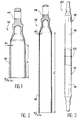
- a preform is shown 10 intended for the subsequent manufacture of a suspension bar. It is important to note that this application is only given as an example, the process according to the invention which can be used in all cases where we want to be able to manufacture a part metallic hollow of revolution having a thickness scalable, relatively small, and very long compared to this thickness. So the process according to the invention can also be used to manufacture including torsion bars, tanks, accumulators, gas generators, bottles high pressure, etc. of a metal such as steel, a light metal, or other.
- Preform 10 is prepared according to the techniques classics prior to flow-forming, in particular by forging then by partial or total machining. Other preparation techniques may, however beings used without departing from the scope of the invention.
- the preform 10 essentially comprises a tubular part 12, as well as a bottom 14 closing the tubular part 12 at one of its ends.
- the preparation of the preform 10 is such that the part tubular 12 and bottom 14 are made in one holding.
- the shape and dimensions of the bottom 14 of the preform 10 are identical to those at the end of the suspension bar you want to make. Of more generally, features such as the shape and dimensions of the bottom of the preform are the same as those of the part to be manufactured. Therefore, these characteristics basically depend the nature of the piece you want to make.
- the bottom 14 can therefore have shapes and dimensions very different, from one room to another, without depart from the scope of the invention.
- the tubular part 12 of the preform 10 contains specific characteristics, different from those of the tubular part of the workpiece, but which directly depend on the characteristics of this last part.
- the tubular part 12 of the preform 10 has a length L relatively short compared to that of the tubular part of the part to be manufactured, and a thickness regularly scalable from one end to the other, and greater than that of the part to be manufactured.
- the shorter character and thicker of the tubular part of the preform 10 relative to the tubular part of the workpiece is a usual feature when the flow turning technique is used.
- the regularly changing character of the thickness of this tubular part 12 of the preform 10 constitutes an original characteristic specific to the invention.
- the thickness of the tubular part 12 of the preform 10 increases regularly from a value el to a value e2, in moving away from the bottom 14 of the preform.
- El values and e2 of the thickness are determined with precision, depending on the thickness of the tubular part of the part to be manufactured, so that the thickness of each section elementary of the tubular part 12 is substantially equal to the thickness of an elementary section corresponding to the tubular part of the part to manufacture, multiplied by a constant coefficient.
- the diameter inside of the tubular part 12 of the preform 10 is identical to that of the tubular part of the part to be manufactured.
- this internal diameter is constant from one end to the other of the part tubular 12.
- the length L can be about 150 mm, the thicknesses el and e2 being then equal to about 4.5 mm and 7.5 mm, respectively.
- the preform 10 illustrated in FIG. 1 is then subjected to a flow-forming operation which allows to transform, in one or more passes, the blank 10 in one piece 16 as illustrated in the Figure 2.
- the part 16 thus obtained comprises the bottom 14, the shape and dimensions of which remain unchanged compared to those of the blank, and a tubular part 18 obtained by flow turning of the tubular part 12 of the draft.
- the tubular part 18 of the part 16 has a length L 'much greater than the length L of the tubular part 12 of the blank, and a thickness significantly reduced compared to that of this tubular part 12.
- the tubular part 18 of the part 16 has also a regularly changing thickness of a end to end.
- This regularly changing thickness of the tubular part 18 of the part 16 is obtained, during flow forming, by reducing the thickness of the tubular part 12 of the preform 10 according to a uniform reduction rate, from one end to the other of this tubular part.
- This uniform reduction rate is equal to the inverse of the coefficient which served initially to determine the thickness of each section elementary of the tubular part 12 of the preform, by multiplying by this coefficient the thickness of a corresponding elementary section of the part to be manufactured.
- the tubular part 18 of part 16 obtained after flow turning, from of the preform 10 may in particular have a length L 'of about 240 mm, a thickness e'1 of about 1.5 mm at its end adjoining the bottom 14 and a thickness e'2 of about 2.5 mm at its open end.
- the uniform reduction rate in this case is 0.33.
- two 16 identical parts can be used to make a suspension bar 20.
- the two pieces 16 are then butt welded along a weld line 22, by the open ends of their parts tubular 18.
- the manufactured part is a part subjected to a internal pressure, such as a fluid reservoir
- a fluid reservoir the scalability of the wall thickness improves noticeably resistant to swelling, while minimizing the weight of the structure.
Applications Claiming Priority (2)
| Application Number | Priority Date | Filing Date | Title |
|---|---|---|---|
| FR9613183 | 1996-10-29 | ||
| FR9613183A FR2755044B1 (fr) | 1996-10-29 | 1996-10-29 | Procede de fabrication d'une piece creuse de revolution, par fluotournage, et piece obtenue par ce procede |
Publications (2)
| Publication Number | Publication Date |
|---|---|
| EP0839593A1 true EP0839593A1 (de) | 1998-05-06 |
| EP0839593B1 EP0839593B1 (de) | 2003-05-21 |
Family
ID=9497136
Family Applications (1)
| Application Number | Title | Priority Date | Filing Date |
|---|---|---|---|
| EP97402538A Expired - Lifetime EP0839593B1 (de) | 1996-10-29 | 1997-10-27 | Verfahren zum Herstellen eines Hohlrevolutionskörpers durch Fliessdrehen |
Country Status (5)
| Country | Link |
|---|---|
| EP (1) | EP0839593B1 (de) |
| AT (1) | ATE240799T1 (de) |
| DE (1) | DE69722129T2 (de) |
| ES (1) | ES2197980T3 (de) |
| FR (1) | FR2755044B1 (de) |
Cited By (5)
| Publication number | Priority date | Publication date | Assignee | Title |
|---|---|---|---|---|
| FR2902358A1 (fr) * | 2006-06-20 | 2007-12-21 | Protac | Procede de fabrication d'un arbre de bielle mecanique |
| EP2241459A1 (de) * | 2008-02-05 | 2010-10-20 | Showa Denko K.K. | Verbindungsteil für ein fahrzeug |
| CN101151472B (zh) * | 2005-03-31 | 2011-03-23 | 法国空中客车公司 | 空心结构连杆以及这种连杆的制造方法 |
| FR2967736A1 (fr) * | 2010-11-22 | 2012-05-25 | Aircelle Sa | Procede de fabrication d'une bielle mecanique tubulaire, et bielle obtenue par un tel procede |
| WO2013017767A1 (fr) | 2011-08-01 | 2013-02-07 | Aircelle | Bielle mécanique tubulaire |
Families Citing this family (2)
| Publication number | Priority date | Publication date | Assignee | Title |
|---|---|---|---|---|
| DE102010029944A1 (de) * | 2010-06-10 | 2011-12-15 | Linde + Wiemann Gmbh Kg | Torsionsrohr für eine Verbundlenkerachse |
| FR3114365B1 (fr) * | 2020-09-23 | 2022-09-09 | Safran Aircraft Engines | Bielle creuse |
Citations (7)
| Publication number | Priority date | Publication date | Assignee | Title |
|---|---|---|---|---|
| US1966713A (en) * | 1928-10-22 | 1934-07-17 | Flint Charles Frederik Vilhelm | Process for the manufacture of metal containers |
| US3055327A (en) * | 1955-09-23 | 1962-09-25 | Lodge & Shipley Co | Metal working |
| US3685475A (en) * | 1969-09-17 | 1972-08-22 | Neill K Banks Jr | Process for producing cup-shaped thin-walled metal wares |
| FR2559078A1 (fr) * | 1984-02-02 | 1985-08-09 | Vallourec | Procede de realisation d'une collerette annulaire sur le fond d'un recipient de revolution |
| DE3440630A1 (de) * | 1984-11-07 | 1986-05-07 | Messerschmitt-Bölkow-Blohm GmbH, 8012 Ottobrunn | Verfahren zur herstellung eines quetschkopfgranaten-gehaeuses |
| FR2632551A1 (fr) * | 1988-06-14 | 1989-12-15 | Aerospatiale | Mandrin expansible et outillage pour la fabrication d'une piece creuse de revolution par fluotournage ou fluorepoussage |
| EP0410884A1 (de) * | 1989-07-26 | 1991-01-30 | AEROSPATIALE Société Nationale Industrielle | Dünnwandige metallische Hochdruckflaschen durch eine Aufwicklung auf Kohlenstoffaserbasis verstärkt und Verfahren zur Herstellung |
-
1996
- 1996-10-29 FR FR9613183A patent/FR2755044B1/fr not_active Expired - Fee Related
-
1997
- 1997-10-27 DE DE69722129T patent/DE69722129T2/de not_active Expired - Lifetime
- 1997-10-27 AT AT97402538T patent/ATE240799T1/de active
- 1997-10-27 EP EP97402538A patent/EP0839593B1/de not_active Expired - Lifetime
- 1997-10-27 ES ES97402538T patent/ES2197980T3/es not_active Expired - Lifetime
Patent Citations (7)
| Publication number | Priority date | Publication date | Assignee | Title |
|---|---|---|---|---|
| US1966713A (en) * | 1928-10-22 | 1934-07-17 | Flint Charles Frederik Vilhelm | Process for the manufacture of metal containers |
| US3055327A (en) * | 1955-09-23 | 1962-09-25 | Lodge & Shipley Co | Metal working |
| US3685475A (en) * | 1969-09-17 | 1972-08-22 | Neill K Banks Jr | Process for producing cup-shaped thin-walled metal wares |
| FR2559078A1 (fr) * | 1984-02-02 | 1985-08-09 | Vallourec | Procede de realisation d'une collerette annulaire sur le fond d'un recipient de revolution |
| DE3440630A1 (de) * | 1984-11-07 | 1986-05-07 | Messerschmitt-Bölkow-Blohm GmbH, 8012 Ottobrunn | Verfahren zur herstellung eines quetschkopfgranaten-gehaeuses |
| FR2632551A1 (fr) * | 1988-06-14 | 1989-12-15 | Aerospatiale | Mandrin expansible et outillage pour la fabrication d'une piece creuse de revolution par fluotournage ou fluorepoussage |
| EP0410884A1 (de) * | 1989-07-26 | 1991-01-30 | AEROSPATIALE Société Nationale Industrielle | Dünnwandige metallische Hochdruckflaschen durch eine Aufwicklung auf Kohlenstoffaserbasis verstärkt und Verfahren zur Herstellung |
Cited By (12)
| Publication number | Priority date | Publication date | Assignee | Title |
|---|---|---|---|---|
| CN101151472B (zh) * | 2005-03-31 | 2011-03-23 | 法国空中客车公司 | 空心结构连杆以及这种连杆的制造方法 |
| FR2902358A1 (fr) * | 2006-06-20 | 2007-12-21 | Protac | Procede de fabrication d'un arbre de bielle mecanique |
| EP1870196A1 (de) * | 2006-06-20 | 2007-12-26 | Protac | Verfahren zur Herstellung eines Mittelrohres eines mechanischen Verbindungsarmes |
| EP2241459A1 (de) * | 2008-02-05 | 2010-10-20 | Showa Denko K.K. | Verbindungsteil für ein fahrzeug |
| EP2241459A4 (de) * | 2008-02-05 | 2011-03-09 | Showa Denko Kk | Verbindungsteil für ein fahrzeug |
| FR2967736A1 (fr) * | 2010-11-22 | 2012-05-25 | Aircelle Sa | Procede de fabrication d'une bielle mecanique tubulaire, et bielle obtenue par un tel procede |
| WO2012069724A1 (fr) * | 2010-11-22 | 2012-05-31 | Aircelle | Procédé de fabrication d'une bielle mécanique tubulaire, et bielle obtenue par un tel procédé |
| CN103221700A (zh) * | 2010-11-22 | 2013-07-24 | 埃尔塞乐公司 | 用于制造管状机械连杆的方法以及使用该方法获得的连杆 |
| US9051963B2 (en) | 2010-11-22 | 2015-06-09 | Aircelle | Method of manufacturing a tubular mechanical link rod and link rod obtained using such a method |
| CN103221700B (zh) * | 2010-11-22 | 2016-01-20 | 埃尔塞乐公司 | 用于制造管状机械连杆的方法以及使用该方法获得的连杆 |
| RU2576308C2 (ru) * | 2010-11-22 | 2016-02-27 | Эрсель | Способ изготовления трубчатого механического соединительного штока и соединительный шток, изготавливаемый таким способом |
| WO2013017767A1 (fr) | 2011-08-01 | 2013-02-07 | Aircelle | Bielle mécanique tubulaire |
Also Published As
| Publication number | Publication date |
|---|---|
| FR2755044A1 (fr) | 1998-04-30 |
| ATE240799T1 (de) | 2003-06-15 |
| DE69722129T2 (de) | 2004-02-19 |
| FR2755044B1 (fr) | 1999-01-08 |
| EP0839593B1 (de) | 2003-05-21 |
| DE69722129D1 (de) | 2003-06-26 |
| ES2197980T3 (es) | 2004-01-16 |
Similar Documents
| Publication | Publication Date | Title |
|---|---|---|
| FR2638114A1 (fr) | Arbre a cames et son procede de fabrication | |
| EP1870196B1 (de) | Verfahren zur Herstellung eines Mittelrohres eines mechanischen Verbindungsarmes | |
| FR2728816A1 (fr) | Procede pour former un element d'arbre et de fourchette monobloc a partir d'un flan de tubage ayant une section transversale generalement circulaire | |
| EP1121553A1 (de) | Gewindeverbindung für zwei metallrohre | |
| EP1864027B1 (de) | Hohlstrukturstange und herstellungsverfahren dafür | |
| FR2651452A1 (fr) | Procede de fabrication d'une soupape. | |
| FR2759483A1 (fr) | Procede de fabrication d'un tube-guide d'un assemblage de combustible d'un reacteur nucleaire, mandrin de formage d'un tube-guide et tube-guide obtenu | |
| EP0839593B1 (de) | Verfahren zum Herstellen eines Hohlrevolutionskörpers durch Fliessdrehen | |
| EP2981371A2 (de) | Verfahren zur herstellung eines rohrförmigen metallteils | |
| FR2731929A1 (fr) | Procede de fabrication d'une boite metallique de forme | |
| EP0648953A1 (de) | Verbesserungen an metallischen Torsionsstäben | |
| CA2302849A1 (fr) | Organe absorbeur de choc et procede de fabrication | |
| EP0099311A1 (de) | Lenkungszahnstange für Kraftfahrzeuge und Prozess zur Herstellung der Zahnstange | |
| EP1355791A1 (de) | Radfelge aus stahlblech mit optimiertem profil | |
| EP1454776B1 (de) | Verbundlenkerachse und Verfahren zur Herstellung eines Querträgers | |
| FR2547896A1 (fr) | Procede de fabrication d'une virole pour recipient de stockage de fluide cryogenique et virole ainsi obtenue | |
| CH622857A5 (de) | ||
| EP1299251A1 (de) | Fahrzeugrad zusammengesetzt unter dem rand der felge | |
| FR2731928A1 (fr) | Procede de fabrication d'une boite metallique de forme | |
| EP1461178B1 (de) | Verfahren zum aufbringen eines schutzüberzugs auf der innenwand eines rohrs, rohr und insbesondere durch das verfahren erhaltenes waffenrohr | |
| EP0895883B1 (de) | Verfahren zur Herstellung eines Fahrzeugstabilisatorstabs | |
| WO2012153182A1 (fr) | Assemblage d'un tube et d'une tôle | |
| FR2791288A1 (fr) | Procede de soudage de tuyaux de raccordement aux extremites opposees d'un bras de suspension de stabilisateur creux pour vehicule | |
| FR2698303A1 (fr) | Procédé de frettage d'au moins une pièce métallique ayant un alésage annulaire autour d'un tube métallique, ensemble obtenu et utilisation du procédé. | |
| EP0864388A1 (de) | Verfahren zum Herstellen einer Kurbelwelle, insbesondere für eine Brennkraftmaschine |
Legal Events
| Date | Code | Title | Description |
|---|---|---|---|
| PUAI | Public reference made under article 153(3) epc to a published international application that has entered the european phase |
Free format text: ORIGINAL CODE: 0009012 |
|
| AK | Designated contracting states |
Kind code of ref document: A1 Designated state(s): AT BE CH DE ES GB IT LI NL SE |
|
| AX | Request for extension of the european patent |
Free format text: AL;LT;LV;RO;SI |
|
| 17P | Request for examination filed |
Effective date: 19981012 |
|
| AKX | Designation fees paid |
Free format text: AT BE CH DE DK ES FI FR GB LI |
|
| RBV | Designated contracting states (corrected) |
Designated state(s): AT BE CH DE DK ES FI FR GB LI |
|
| RBV | Designated contracting states (corrected) |
Designated state(s): AT BE CH DE ES GB IT LI NL SE |
|
| 17Q | First examination report despatched |
Effective date: 20020502 |
|
| RAP1 | Party data changed (applicant data changed or rights of an application transferred) |
Owner name: EUROPEAN AERONAUTIC DEFENCE AND SPACE COMPANY - EA |
|
| RTI1 | Title (correction) |
Free format text: METHOD OF MAKING A HOLLOW REVOLUTION PART BY FLUOTURNING |
|
| GRAH | Despatch of communication of intention to grant a patent |
Free format text: ORIGINAL CODE: EPIDOS IGRA |
|
| GRAH | Despatch of communication of intention to grant a patent |
Free format text: ORIGINAL CODE: EPIDOS IGRA |
|
| GRAA | (expected) grant |
Free format text: ORIGINAL CODE: 0009210 |
|
| AK | Designated contracting states |
Designated state(s): AT BE CH DE ES GB IT LI NL SE |
|
| REG | Reference to a national code |
Ref country code: GB Ref legal event code: FG4D Free format text: NOT ENGLISH |
|
| REG | Reference to a national code |
Ref country code: CH Ref legal event code: EP |
|
| REF | Corresponds to: |
Ref document number: 69722129 Country of ref document: DE Date of ref document: 20030626 Kind code of ref document: P |
|
| REG | Reference to a national code |
Ref country code: SE Ref legal event code: TRGR |
|
| GBT | Gb: translation of ep patent filed (gb section 77(6)(a)/1977) | ||
| REG | Reference to a national code |
Ref country code: ES Ref legal event code: FG2A Ref document number: 2197980 Country of ref document: ES Kind code of ref document: T3 |
|
| PLBE | No opposition filed within time limit |
Free format text: ORIGINAL CODE: 0009261 |
|
| STAA | Information on the status of an ep patent application or granted ep patent |
Free format text: STATUS: NO OPPOSITION FILED WITHIN TIME LIMIT |
|
| 26N | No opposition filed |
Effective date: 20040224 |
|
| PGFP | Annual fee paid to national office [announced via postgrant information from national office to epo] |
Ref country code: AT Payment date: 20101014 Year of fee payment: 14 |
|
| PGFP | Annual fee paid to national office [announced via postgrant information from national office to epo] |
Ref country code: DE Payment date: 20101022 Year of fee payment: 14 |
|
| PGFP | Annual fee paid to national office [announced via postgrant information from national office to epo] |
Ref country code: GB Payment date: 20101021 Year of fee payment: 14 Ref country code: IT Payment date: 20101026 Year of fee payment: 14 |
|
| PGFP | Annual fee paid to national office [announced via postgrant information from national office to epo] |
Ref country code: SE Payment date: 20111021 Year of fee payment: 15 Ref country code: BE Payment date: 20111013 Year of fee payment: 15 Ref country code: CH Payment date: 20111024 Year of fee payment: 15 Ref country code: ES Payment date: 20111021 Year of fee payment: 15 Ref country code: NL Payment date: 20111025 Year of fee payment: 15 |
|
| BERE | Be: lapsed |
Owner name: EUROPEAN AERONAUTIC DEFENCE AND SPACE CY - *EADS F Effective date: 20121031 |
|
| REG | Reference to a national code |
Ref country code: NL Ref legal event code: V1 Effective date: 20130501 |
|
| REG | Reference to a national code |
Ref country code: CH Ref legal event code: PL |
|
| REG | Reference to a national code |
Ref country code: AT Ref legal event code: MM01 Ref document number: 240799 Country of ref document: AT Kind code of ref document: T Effective date: 20121027 |
|
| GBPC | Gb: european patent ceased through non-payment of renewal fee |
Effective date: 20121027 |
|
| PG25 | Lapsed in a contracting state [announced via postgrant information from national office to epo] |
Ref country code: CH Free format text: LAPSE BECAUSE OF NON-PAYMENT OF DUE FEES Effective date: 20121031 Ref country code: GB Free format text: LAPSE BECAUSE OF NON-PAYMENT OF DUE FEES Effective date: 20121027 Ref country code: LI Free format text: LAPSE BECAUSE OF NON-PAYMENT OF DUE FEES Effective date: 20121031 Ref country code: SE Free format text: LAPSE BECAUSE OF NON-PAYMENT OF DUE FEES Effective date: 20121028 Ref country code: DE Free format text: LAPSE BECAUSE OF NON-PAYMENT OF DUE FEES Effective date: 20130501 Ref country code: AT Free format text: LAPSE BECAUSE OF NON-PAYMENT OF DUE FEES Effective date: 20121027 Ref country code: BE Free format text: LAPSE BECAUSE OF NON-PAYMENT OF DUE FEES Effective date: 20121031 |
|
| REG | Reference to a national code |
Ref country code: DE Ref legal event code: R119 Ref document number: 69722129 Country of ref document: DE Effective date: 20130501 |
|
| PG25 | Lapsed in a contracting state [announced via postgrant information from national office to epo] |
Ref country code: NL Free format text: LAPSE BECAUSE OF NON-PAYMENT OF DUE FEES Effective date: 20130501 Ref country code: IT Free format text: LAPSE BECAUSE OF NON-PAYMENT OF DUE FEES Effective date: 20121027 |
|
| REG | Reference to a national code |
Ref country code: ES Ref legal event code: FD2A Effective date: 20140116 |
|
| PG25 | Lapsed in a contracting state [announced via postgrant information from national office to epo] |
Ref country code: ES Free format text: LAPSE BECAUSE OF NON-PAYMENT OF DUE FEES Effective date: 20121028 |