EP0839482A2 - Präsentationssystem - Google Patents
Präsentationssystem Download PDFInfo
- Publication number
- EP0839482A2 EP0839482A2 EP97650040A EP97650040A EP0839482A2 EP 0839482 A2 EP0839482 A2 EP 0839482A2 EP 97650040 A EP97650040 A EP 97650040A EP 97650040 A EP97650040 A EP 97650040A EP 0839482 A2 EP0839482 A2 EP 0839482A2
- Authority
- EP
- European Patent Office
- Prior art keywords
- bin
- display
- side walls
- bins
- cabinet
- Prior art date
- Legal status (The legal status is an assumption and is not a legal conclusion. Google has not performed a legal analysis and makes no representation as to the accuracy of the status listed.)
- Withdrawn
Links
- 238000009423 ventilation Methods 0.000 claims abstract description 15
- 238000001816 cooling Methods 0.000 claims abstract description 9
- 239000004033 plastic Substances 0.000 claims abstract description 6
- 229920003023 plastic Polymers 0.000 claims abstract description 6
- 239000000463 material Substances 0.000 claims description 12
- 238000010276 construction Methods 0.000 claims description 10
- 230000001737 promoting effect Effects 0.000 abstract 1
- 229920000139 polyethylene terephthalate Polymers 0.000 description 10
- 239000005020 polyethylene terephthalate Substances 0.000 description 10
- 238000004140 cleaning Methods 0.000 description 5
- 230000002411 adverse Effects 0.000 description 2
- 230000015572 biosynthetic process Effects 0.000 description 2
- 238000005520 cutting process Methods 0.000 description 2
- 238000005755 formation reaction Methods 0.000 description 2
- 238000003860 storage Methods 0.000 description 2
- 238000004026 adhesive bonding Methods 0.000 description 1
- 150000001875 compounds Chemical class 0.000 description 1
- 235000013611 frozen food Nutrition 0.000 description 1
- 229920001519 homopolymer Polymers 0.000 description 1
- 238000004519 manufacturing process Methods 0.000 description 1
- 238000000034 method Methods 0.000 description 1
- 238000012856 packing Methods 0.000 description 1
- -1 polyethylene terephthalate Polymers 0.000 description 1
- 239000012780 transparent material Substances 0.000 description 1
- 230000007306 turnover Effects 0.000 description 1
- 238000003466 welding Methods 0.000 description 1
Images


Classifications
-
- A—HUMAN NECESSITIES
- A47—FURNITURE; DOMESTIC ARTICLES OR APPLIANCES; COFFEE MILLS; SPICE MILLS; SUCTION CLEANERS IN GENERAL
- A47F—SPECIAL FURNITURE, FITTINGS, OR ACCESSORIES FOR SHOPS, STOREHOUSES, BARS, RESTAURANTS OR THE LIKE; PAYING COUNTERS
- A47F3/00—Show cases or show cabinets
- A47F3/04—Show cases or show cabinets air-conditioned, refrigerated
- A47F3/0482—Details common to both closed and open types
- A47F3/0486—Details common to both closed and open types for charging, displaying or discharging the articles
-
- A—HUMAN NECESSITIES
- A47—FURNITURE; DOMESTIC ARTICLES OR APPLIANCES; COFFEE MILLS; SPICE MILLS; SUCTION CLEANERS IN GENERAL
- A47F—SPECIAL FURNITURE, FITTINGS, OR ACCESSORIES FOR SHOPS, STOREHOUSES, BARS, RESTAURANTS OR THE LIKE; PAYING COUNTERS
- A47F3/00—Show cases or show cabinets
- A47F3/14—Display trays or containers
Definitions
- This invention relates to a display system and to a display bin for use in the display system.
- the invention is particulary concerned with the display of goods for sale in shops and the like. More particularly, the invention is primarily concerned with the display of chilled goods for sale in freezer cabinets.
- freezer cabinet includes refrigerated cabinets for storing chilled or frozen food products.
- the present invention is directed towards overcoming these problems.
- a display system for a display cabinet comprising a plurality of independent display bins for mounting in the display cabinet to sub-divide the display cabinet into a number of smaller display units or compartments.
- the use of the independent display bins has a number of advantages.
- a set of display bins can be mounted within the cabinet, each for storing and displaying selected goods. For restocking, a bin is simply removed and replaced with a charged bin and any remaining old stock in the old bin can simply be tipped into the new bin. Thus, restocking can be carried out quickly and advantageously the old stock will always be uppermost in the bins.
- the display system has means for defining cooling air circulation passages around the bins when a set of juxtaposed bins are mounted within the display cabinet.
- a display bin for use in the system has a number of ventilation openings in the side walls for ventilating the bin during use.
- the ventilation openings comprise a number of spaced-apart slots in opposite side walls of the bin. This encourages air flow through the bin in use for optimum cooling with minimal frost build up.
- ventilation openings may be provided in all the side walls.
- the slots may comprise elongate slots arranged in either a vertical or horizontal orientation on the side walls.
- Various other ventilation slot configurations are possible.
- one or more drainage holes is provided in a base of the bin.
- a support leg or legs are provided on the base to raise the base from a support surface on which the bin is mounted.
- This construction advantageously prevents moisture collecting in the bin which might adversely affect goods within the bin or lead to frost build-up which is undesirable.
- the drainage holes also allow air circulation through the bin.
- one or more ribs or projections are provided on side walls of the bin.
- the ribs extend around the side walls intermediate the ends of the side walls.
- the ribs strengthen the side walls.
- the ribs essentially ensure air passageways are formed between the bins for good circulation of cooling air around and through the bins which again promotes good cooling and minimises frost formation.
- the ribs may comprise a broken line of projections extending outwardly from the side walls. Any other suitable arrangement of projections may be provided to keep the bins spaced-apart from each other and from side walls of the cabinet in which they are mounted in use.
- the spacing of a rib which extends around the side walls above the base may be selected so that the depth of the bin may be reduced by cutting around the side walls at the rib leaving a rim at a top of the bin.
- a standard sized bin may be produced for use in a range of different display cabinets, the depth of the bin simply being adjusted as necessary for the particular display cabinet in which the bin is to be mounted.
- the bin may be of two-part construction comprising a pair of interengagable bin halves with means for securing the bin halves together to form the display bin.
- Each bin half comprises portion of the base and the associated side wall portions.
- the two bin halves may be secured together by any suitable means, for example using fasteners such as rivets, stitching, welding or gluing.
- This construction of display bin is advantageous from a manufacturing point of view in that it is generally simpler and cheaper to mould two halves than a complete bin, particularly with larger sized bins. Further, for transport a plurality of bin halves can be nested together for more efficient packing during transport.
- an internal divider may be provided for a display bin to separate the interior of the bin into a number of smaller compartments.
- the bin may be provided with tapered side walls to allow nesting of a number of the bins together to facilitate storage and transport of bins.
- the base and the upper rim of the bins are interengagable for stacking bins.
- the display bin is constructed of a translucent material. Most preferably the bin is of transparent material to assist in displaying goods contained within the bin. The material may be coloured or tinted if desired.
- the display bin is constructed of a plastics material. Any suitable plastics material may be used, however most preferably the plastics material is PET (polyethylene terephthalate).
- PET polyethylene terephthalate
- the term PET is to be understood to include the following: crystallizable and amorphous PET homopolymers, crystallizable and amorphous PET oopolymers, crystallizable and amorphous PET compounds, crystallizable and amorphous recycled PET and other variants of amorphous and crystallizable PET.
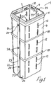
- a display bin according to the invention indicated generally by the reference numeral 1.
- a number of the display bins 1 are used to form a display system according to the invention comprising a number of the display bins 1 arranged within a freezer cabinet 2 (Fig. 6) subdividing the freezer cabinet 2 into a number of smaller display compartments each containing products 3 for sale.
- Each bin 1 comprises a rectangular base 5 with upstanding side walls on the base, the side walls comprising a front wall 6, a rear wall 7, interconnected by sides 8, 9.
- An access opening 10 for filling and removing products 3 from the bin 1 is defined by a rim 11 extending around an upper end of the side walls 6, 7, 8, 9.
- a number of ventilation openings 12 are provided by spaced-apart slots in the front wall 6 and rear wall 7. Although not illustrated, additional ventilation openings 12 may be provided in the sides 8, 9 also if desired. It will be noted that the ventilation openings 12 extend between the base 5 and the rim 11 to provide good air circulation throughout the bin 1.
- a number of drainage holes 14 are provided in the base 5. Also, support legs 15 project downwardly from the base 5, to raise the base 5 from a support surface 16 (Fig. 2) on which the bin 1 is mounted.
- the drainage holes 14 prevent build up of moisture in the bin 1 which might adversely affect goods in the bin 1 particularly those goods at the bottom of the bin 1, and also assist in air circulation through the bin 1.
- a plurality of ribs 18 extend around the side walls 6, 7, 8, 9 intermediate the base 5 and the rim 11.
- the ribs 18 are generally horizontal however it will be appreciated that various other rib formations or projections are possible.
- the ribs 18, and indeed the rim 11 keep the side walls of adjacent bins 1 apart when mounted in the cabinet 2 shown in Fig. 6, thus effectively forming cooling air circulation passageways between and around the bins 1 for good air circulation around and through the bins 1. This promotes optimum cooling of the products within the bins 1 and minimises frost build-up.
- An advantage of the generally horizontal arrangement of the ribs 18 as shown in the drawings is that the ribs 18 can be spaced above the base 5 at selected intervals. This provides the possibility of cutting around the side walls 6, 7, 8, 9 at a rib 18 to reduce the depth of the bin 1 if desired for fitting the bin 1 into different sized display cabinets.
- the bin is of two-part construction comprising a pair of interengagable bin halves 20, 21 with overlapping and interengagable flanges 22, 23 respectively.
- the two bin halves 20, 21 are interconnected by a number of spaced-apart rivets 24 which interlock the flanges 22, 23.
- Various other methods for securing the bin halves 20, 21 together are possible.
- each bin half 20, 21 comprises roughly one half of the base 5, one of the front wall 6 and rear wall 7, and roughly one half of each of the sides 8, 9. It will be noted that the bin halves 20, 21 can be nested together for storage which is convenient for transport.
- the bin 1 is constructed of a substantially transparent PET material, although other materials may be used if desired.
- a number of the bins 1 are mounted in a freezer cabinet 2 as shown in Fig. 6.
- Products 3 for sale are then stored in each of the bins 1 which display the products 3 for sale in an attractive manner.
- some positions within a display cabinet 2 are better than others for selling goods.
- the goods 3 in the bins 1 can be readily easily moved around the freezer cabinet 2 to display different goods 3 in the optimum selling position at different times.
- cooling of the products is optimised and the build up of frost within the cabinet is minimised. Any frost build-up on the side walls of the freezer cabinet 2 is readily, easily and quickly removed by taking out the bins 1 along the freezer cabinet side wall to provide immediate access to the side wall for cleaning.
- a bin 1 can simply be removed and replaced with a fresh bin 1 containing the fresh stock. Any few remaining goods 3 in the old bin can be simply be tipped into the new bin so that the old stock will be used first. Thus advantageously there is no build-up of old stock at the bottom of the freezer cabinet 2 which can lead to wastage.
- Fig. 7 shows a display bin 30 according to another embodiment of the invention. Parts similar to those described previously are assigned the same reference numerals.
- the display bin 30 is of one piece construction. Ventilation openings in the front wall 6 and rear wall 7 are provided by a number of spaced-apart elongate slots 32, each slot 32 arranged in a generally horizontal orientation on the bin side walls 6, 7.
- Fig. 8 shows another display bin 40. Parts similar to those described previously are assigned the same reference numerals.
- each rib 18 is formed by a broken line of projections 42 extending around the side walls 6, 7, 8, 9.
- ventilation openings 43 are provided in all side walls 6, 7, 8, 9.
- the display bin according to the invention may be made in the two-part construction or it may be of one piece construction.
- Various different materials may be used for construction the bin, however plastics material is preferred and in particular PET material.
- Various different arrangements of the ventilation holes and drainage holes in the bin may be provided and in some cases the drainage holes and/or the ventilation holes may be omitted if desired.
- bins may be provided without support legs on the base. It may be desirable to fit rails or other raised supports along a bottom of the freezer cabinet instead to support the bins above the bottom of the freezer cabinet facilitating drainage from the bins.
Landscapes
- Physics & Mathematics (AREA)
- Thermal Sciences (AREA)
- Freezers Or Refrigerated Showcases (AREA)
- Cold Air Circulating Systems And Constructional Details In Refrigerators (AREA)
- Removal Of Water From Condensation And Defrosting (AREA)
Applications Claiming Priority (2)
| Application Number | Priority Date | Filing Date | Title |
|---|---|---|---|
| IE960712 | 1996-10-07 | ||
| IE960712 | 1996-10-07 |
Publications (2)
| Publication Number | Publication Date |
|---|---|
| EP0839482A2 true EP0839482A2 (de) | 1998-05-06 |
| EP0839482A3 EP0839482A3 (de) | 1999-07-21 |
Family
ID=11041277
Family Applications (1)
| Application Number | Title | Priority Date | Filing Date |
|---|---|---|---|
| EP97650040A Withdrawn EP0839482A3 (de) | 1996-10-07 | 1997-10-07 | Präsentationssystem |
Country Status (2)
| Country | Link |
|---|---|
| EP (1) | EP0839482A3 (de) |
| IE (2) | IES20000209A2 (de) |
Cited By (2)
| Publication number | Priority date | Publication date | Assignee | Title |
|---|---|---|---|---|
| WO2000070282A1 (en) * | 1999-05-12 | 2000-11-23 | Unilever Plc | A compartmentalisation bin |
| WO2014082973A1 (en) | 2012-11-30 | 2014-06-05 | Unilever Plc | Storage and display system for a freezer |
Family Cites Families (9)
| Publication number | Priority date | Publication date | Assignee | Title |
|---|---|---|---|---|
| US1701019A (en) * | 1927-03-24 | 1929-02-05 | Leslie T Summers | Meat cooling and dispensing case |
| FR2465447A1 (fr) * | 1979-09-26 | 1981-03-27 | Bourjois Sa | Presentoir modulaire notamment pour produits cosmetiques |
| CH658333A5 (de) * | 1981-12-22 | 1986-10-31 | Wiederaufarbeitung Von Kernbre | Behaelter fuer die langzeitlagerung von radioaktiven stoffen, insbesondere abgebrannte kernreaktorbrennelemente. |
| FR2596026B1 (fr) * | 1986-03-18 | 1988-12-02 | Oddoux Claude | Emballage pour fromage frais |
| DE3910735A1 (de) * | 1989-04-03 | 1990-10-04 | Berolina Kunststoff | Teilbarer flaschenkasten |
| JPH03200584A (ja) * | 1989-12-28 | 1991-09-02 | Taiyo Kagaku Kogyo Kk | 生鮮食品用容器 |
| GB2257351A (en) * | 1991-05-21 | 1993-01-13 | * Haagen-Dazs Uk Limited | Display apparatus |
| IT230329Y1 (it) * | 1993-07-01 | 1999-06-02 | Sviluppo Settori Impiego Srl | Cassetta pieghevole per ortofrutta |
| JPH0891463A (ja) * | 1994-09-30 | 1996-04-09 | Mitsubishi Chem Basf Co Ltd | 魚 箱 |
-
1997
- 1997-10-07 EP EP97650040A patent/EP0839482A3/de not_active Withdrawn
- 1997-10-07 IE IE20000209A patent/IES20000209A2/xx not_active IP Right Cessation
- 1997-10-07 IE IE970727A patent/IE970727A1/en not_active IP Right Cessation
Cited By (2)
| Publication number | Priority date | Publication date | Assignee | Title |
|---|---|---|---|---|
| WO2000070282A1 (en) * | 1999-05-12 | 2000-11-23 | Unilever Plc | A compartmentalisation bin |
| WO2014082973A1 (en) | 2012-11-30 | 2014-06-05 | Unilever Plc | Storage and display system for a freezer |
Also Published As
| Publication number | Publication date |
|---|---|
| IE970727A1 (en) | 1998-04-08 |
| IES20000209A2 (en) | 2000-08-09 |
| EP0839482A3 (de) | 1999-07-21 |
Similar Documents
| Publication | Publication Date | Title |
|---|---|---|
| CN100572201C (zh) | 多隔间容器和盖子组件 | |
| US6565169B1 (en) | Double crisper drawer for a refrigerator | |
| US6745905B2 (en) | Ventilated tray for refrigerator beverage packages | |
| US4176747A (en) | Stackable crates | |
| US6766931B2 (en) | Grocery-store shopping cart facilitating diverse-condition cartage | |
| US4561705A (en) | Compartmented transport and storage container | |
| US20020088244A1 (en) | Point of sale product chiller | |
| EP2060500A1 (de) | Transport- und Display-Verpackungsanordnung | |
| EP2745062B1 (de) | Ausgabebehälter für temperaturempfindliche waren | |
| US6237772B1 (en) | Assembly of interconnected containers and containers for use therein | |
| US4615443A (en) | Beverage bottle package display system | |
| US4510770A (en) | Chest for storing, cooling and dispensing comestibles | |
| JPH11511050A (ja) | 引き出し付き冷却カウンター | |
| EP0839482A2 (de) | Präsentationssystem | |
| US20240109686A1 (en) | Modular channel panel | |
| JP2004506862A (ja) | 冷蔵庫用保存トレイ | |
| US2000944A (en) | Refrigerator article receptacle | |
| WO2000070282A1 (en) | A compartmentalisation bin | |
| EP0919164B1 (de) | Präsentationssystem | |
| US6220465B1 (en) | Freezer organizer system | |
| DE102010038377B4 (de) | Kühlgutbehälter | |
| US20220281641A1 (en) | Channeled divider panel and method thereof | |
| US20070052331A1 (en) | Interchangeable storage system and associated method of use | |
| JPH07239179A (ja) | 冷蔵庫 | |
| JP2609958B2 (ja) | ショーケース用ラック |
Legal Events
| Date | Code | Title | Description |
|---|---|---|---|
| PUAI | Public reference made under article 153(3) epc to a published international application that has entered the european phase |
Free format text: ORIGINAL CODE: 0009012 |
|
| AK | Designated contracting states |
Kind code of ref document: A2 Designated state(s): AT BE CH DE DK ES FI FR GB GR IE IT LI LU MC NL PT SE |
|
| PUAL | Search report despatched |
Free format text: ORIGINAL CODE: 0009013 |
|
| AK | Designated contracting states |
Kind code of ref document: A3 Designated state(s): AT BE CH DE DK ES FI FR GB GR IE IT LI LU MC NL PT SE |
|
| 17P | Request for examination filed |
Effective date: 20000117 |
|
| AKX | Designation fees paid |
Free format text: AT BE CH DE DK ES FI FR GB GR IE IT LI LU MC NL PT SE |
|
| 17Q | First examination report despatched |
Effective date: 20020328 |
|
| GRAP | Despatch of communication of intention to grant a patent |
Free format text: ORIGINAL CODE: EPIDOSNIGR1 |
|
| GRAS | Grant fee paid |
Free format text: ORIGINAL CODE: EPIDOSNIGR3 |
|
| STAA | Information on the status of an ep patent application or granted ep patent |
Free format text: STATUS: THE APPLICATION IS DEEMED TO BE WITHDRAWN |
|
| 18D | Application deemed to be withdrawn |
Effective date: 20050503 |