EP0838908A2 - Näherungsdetektor eines Funktelefons - Google Patents
Näherungsdetektor eines Funktelefons Download PDFInfo
- Publication number
- EP0838908A2 EP0838908A2 EP97308483A EP97308483A EP0838908A2 EP 0838908 A2 EP0838908 A2 EP 0838908A2 EP 97308483 A EP97308483 A EP 97308483A EP 97308483 A EP97308483 A EP 97308483A EP 0838908 A2 EP0838908 A2 EP 0838908A2
- Authority
- EP
- European Patent Office
- Prior art keywords
- proximity
- radiotelephone
- telephone
- unit
- detector
- Prior art date
- Legal status (The legal status is an assumption and is not a legal conclusion. Google has not performed a legal analysis and makes no representation as to the accuracy of the status listed.)
- Granted
Links
Images


Classifications
-
- H—ELECTRICITY
- H04—ELECTRIC COMMUNICATION TECHNIQUE
- H04M—TELEPHONIC COMMUNICATION
- H04M1/00—Substation equipment, e.g. for use by subscribers
- H04M1/72—Mobile telephones; Cordless telephones, i.e. devices for establishing wireless links to base stations without route selection
- H04M1/724—User interfaces specially adapted for cordless or mobile telephones
-
- H—ELECTRICITY
- H04—ELECTRIC COMMUNICATION TECHNIQUE
- H04B—TRANSMISSION
- H04B1/00—Details of transmission systems, not covered by a single one of groups H04B3/00 - H04B13/00; Details of transmission systems not characterised by the medium used for transmission
- H04B1/38—Transceivers, i.e. devices in which transmitter and receiver form a structural unit and in which at least one part is used for functions of transmitting and receiving
- H04B1/3827—Portable transceivers
- H04B1/3833—Hand-held transceivers
- H04B1/3838—Arrangements for reducing RF exposure to the user, e.g. by changing the shape of the transceiver while in use
-
- H—ELECTRICITY
- H04—ELECTRIC COMMUNICATION TECHNIQUE
- H04M—TELEPHONIC COMMUNICATION
- H04M1/00—Substation equipment, e.g. for use by subscribers
- H04M1/02—Constructional features of telephone sets
- H04M1/04—Supports for telephone transmitters or receivers
-
- H—ELECTRICITY
- H04—ELECTRIC COMMUNICATION TECHNIQUE
- H04W—WIRELESS COMMUNICATION NETWORKS
- H04W52/00—Power management, e.g. TPC [Transmission Power Control], power saving or power classes
- H04W52/02—Power saving arrangements
- H04W52/0209—Power saving arrangements in terminal devices
- H04W52/0251—Power saving arrangements in terminal devices using monitoring of local events, e.g. events related to user activity
-
- Y—GENERAL TAGGING OF NEW TECHNOLOGICAL DEVELOPMENTS; GENERAL TAGGING OF CROSS-SECTIONAL TECHNOLOGIES SPANNING OVER SEVERAL SECTIONS OF THE IPC; TECHNICAL SUBJECTS COVERED BY FORMER USPC CROSS-REFERENCE ART COLLECTIONS [XRACs] AND DIGESTS
- Y02—TECHNOLOGIES OR APPLICATIONS FOR MITIGATION OR ADAPTATION AGAINST CLIMATE CHANGE
- Y02D—CLIMATE CHANGE MITIGATION TECHNOLOGIES IN INFORMATION AND COMMUNICATION TECHNOLOGIES [ICT], I.E. INFORMATION AND COMMUNICATION TECHNOLOGIES AIMING AT THE REDUCTION OF THEIR OWN ENERGY USE
- Y02D30/00—Reducing energy consumption in communication networks
- Y02D30/70—Reducing energy consumption in communication networks in wireless communication networks
Definitions
- the present invention relates to a radiotelephone proximity detector.
- Portable radiotelephones by virtue of their mobility are easily misplaced or stolen.
- the present invention aims generally to tackle these problems. More specifically when a radiotelephone is misplaced or stolen, it is vulnerable to misuse by an unauthorised person particularly if it is misplaced or stolen when the security lock is not activated. An unauthorised person is then able to place calls which are charged to the owner of the radiotelephone and also access confidential information which may be stored in the radiotelephone's memory.
- the present invention provides a radiotelephone proximity detector, comprising a first proximity unit associated with a radiotelephone and a second proximity unit associated with a user, wherein the second proximity unit includes a transmitter for transmitting a proximity signal, and the first proximity unit includes a receiver for receiving the proximity signal and an analysis unit for estimating the proximity of the first and second proximity units on the basis of the received proximity signal, the first proximity unit being operable when the estimated proximity of the first and second proximity units exceeds a threshold to cause the radiotelephone to change into an operating mode in which its normal use is prevented.
- the first proximity unit estimates the proximity of the first and second proximity units by comparing the received signal strength of a proximity signal transmitted by the second proximity unit with a threshold. If this received signal strength falls below the threshold, then the first proximity unit estimates that the second proximity unit is too far away from the first proximity unit and causes the radiotelephone to change into an operating mode in which its normal use is prevented.
- the security lock may be activated such that the radiotelephone may require a correct personal identification or so-called PIN number is entered before any further use can be made of the phone.
- the call placing capability of the radiotelephone may be inhibited but the capability to receive a call may be available. Additionally, the capability to access user-definable data, such as menu structures and phone number/name lists, may also be inhibited.
- the proximity of the first and second proximity units is estimated by the time taken for the proximity signals to travel between the first and second proximity units.
- the first proximity unit is located within the casing of the radiotelephone and is powered by the battery of the radiotelephone.
- the transmitter of the second proximity unit is preferably dedicated to the task of monitoring the first and second proximity units.
- the main transceiver of the radiotelephone which transmits and receives signals to and from the cellular network can also perform the role of the receiver of the second proximity unit.
- the second proximity unit is associated with the user by being integrated with means which are ordinarily worn or carried by the user, for example, a belt clip assembly, a hearing aid, a brief case or a case for carrying the radiotelephone.
- the communication link is preferably established using radio wave transmission, but other techniques such as ultrasonic wave transmission can also be used.
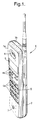
- the telephone apparatus shown in Figure 1 is a cellular mobile telephone having an A or front cover 3a and a B or rear cover 3b powered by a rechargeable battery pack 2.
- the telephone 1 includes a transceiver 9 for transmitting and receiving signals to and from the cellular network and all the other features conventionally found in a cellular telephone, as shown schematically in Figure 2. Since these aspects of the telephone are not directly relevant to the instant invention no further details will be given here, except to say that a microprocessor 4 (see Figure 2) is employed to control all the basic functions of the telephone 1 and to control the keypad, display functions and a tone generator 12. Additionally, a memory 14 is provided for storing third party subscriber telephone records.
- the user-interface of telephone 1 comprises a display, e.g.
- the display is coupled to and regulated by the microprocessor 4.
- the keypad 6 essentially comprises two main sets of keys, namely alphanumeric keys 6a associated with alphanumeric data especially for dialling telephone numbers, but also for entering alphanumeric data into the telephone number store 14; and a set of function keys 6b for enabling various predetermined functions or operations.
- the telephone also includes a microphone 7, a loudspeaker 8, and a proximity unit 16 which will be described in greater detail later.
- the mobile telephone is equipped with a belt clip assembly 20 which enables a user to attach the telephone 1 to his belt for convenient transportation when the telephone is not in use.
- the belt clip assembly 20 is in its mechanical aspects largely known in the art. Full details of its mechanical construction can be found in EP-A1-683587, but for the sake of completeness the following brief description is included.
- the belt clip assembly 20 comprises a clip member 22 as shown in Figure 5.
- the clip member 22 removably snap-fits onto the rear of the telephone casing.
- the clip member 22 includes a planar member 24 having bent ends which serve as arms 25 to removably grasp in a snap-fit manner the telephone casing as shown in Figure 3.
- a first fastening element 26 upstands from the planar member 24.
- the belt clip assembly 20 further comprises a body portion 28 which attaches to a belt 30 of a user.
- the body portion 28 comprises a back member 32 from which rearwardly projects a j-shaped member 34 and a protrusion 36.
- the j-shaped member 34 and the protrusion 36 define a channel 38 as shown in Figure 3 within which the belt 30 can be slid and retained.
- Guide flanges 40 project forwardly from the back member 32 and define a region 41 into which the first fastening element 26 of the clip member 22 can be slid.
- a second fastening element 42 projects forwardly into the region 41 and can co-operate with the first fastening element 26 to secure the clip member 22 and hence the telephone in place.
- the belt clip assembly 20 further comprises a proximity unit 46 mounted to the rear of the back member 32.
- the telephone proximity unit 16 and the belt clip assembly proximity unit 46 are shown in Figure 6.
- the belt clip assembly proximity unit 46 is powered by a low power supply 50 including a replaceable battery.
- the proximity unit 46 also comprises a controller 52 which controls the operation of a transceiver 54.
- the controller 52 can be implemented as dedicated combinational logic or as a microprocessor.
- the transceiver 54 comprises a transmitter 56 and a receiver 58 for transmitting and receiving a lower power ultra high frequency (UHF) signals to and from the telephone proximity unit 16, respectively.
- UHF ultra high frequency
- the transceiver 54 under control of the controller 52, can be switched into a reduced power mode in which the transmitter 56 is non-operational.
- the controller 52 also controls a loudspeaker 57, the output volume of which is controllable by the user via a potentiometer 59.
- a slideable control member of the potentiometer 59 is denoted in Figure 3 by reference numeral 59a.
- the controller 52 is also responsive to the state of a depressable key 60.
- the telephone proximity unit 16 is powered by the battery 2 of the telephone.
- the proximity unit 16 also comprises a controller 72 which controls the operation of a transceiver 74.
- the controller 72 can be implemented as dedicated combinational logic or as a microprocessor.
- the transceiver 74 comprises a transmitter 76 and a receiver 78 for transmitting and receiving lower power ultra high frequency (UHF) signals to and from the proximity unit 46, respectively.
- UHF ultra high frequency
- the transceiver 74 under the control of the controller 72, can be switched into a reduced power mode in which the transmitter 76 is non-operational.
- the controller 72 is controlled by the microprocessor 4 of the telephone 1.
- the belt clip proximity unit 46 further comprises detection circuitry 61 having a detecting contact 62.
- the detecting contact 62 is located, as can be seen in Figure 4, in the second fastening element 42.
- the telephone proximity unit 16 further comprises detection circuitry 81 having a detecting contact 82.
- the detecting contact 82 projects through the rear casing or cover 3b so as to be located, as can be seen in Figure 3, in the first fastening element 26.
- the transmitter 56 is operable to transmit a signal S1 comprising a carrier signal at a frequency F1 having identification coding C1, indicating the belt clip proximity unit 46 as the origin of the signal, modulated into it.
- the receiver 78 is operable to receive and demodulate the identification coding from the signal S1 and communicates this and also the power or strength of the received signal to the controller 72.
- the transmitter 76 is operable to transmit a signal S2 comprising a carrier signal at frequency F2 having identification coding C2, indicating the telephone proximity unit 16 as the origin of the signal, modulated into it.
- the receiver 58 is operable to receive and demodulate the identification coding from the signal S2 and communicates this and also the power or strength of the received signal to the controller 52.
- the belt clip proximity unit 46 and the telephone proximity unit 16 are a 'matched pair' in that the belt clip proximity unit 46 is pre-programmed to recognise the identification coding C2 of the telephone proximity unit 16 and vice versa.
- the proximity units 16, 46 switch on and operate as shown in the flow diagram of Figure 7.
- the telephone proximity units 16 acts as master and the belt clip proximity unit 46 acts as slave.
- its transmitter 76 transmits master proximity signal S2 at step 102. After this transmission, the transmitter is switched into reduced power mode at step 104.
- its receiver 78 waits to receive the slave acknowledgement proximity signal S1 from the 'matched' belt clip proximity unit 46. If no signal is received within a predetermined interval, say T, or within this interval a signal is received but the identification coding does not match or equal C1, step 108 is executed by which an alarm is sounded for a brief interval.
- step 108 is again executed.
- Figure 8(a) shows this situation with the boundary B1, indicating the region where the received signal strength of S1 equals the first threshold.
- the region within the boundary B1 is referred to as the telephone control field TCF.
- the telephone proximity unit 16 sounds the alarm at step 108 as a result of having failed to receive an acceptable acknowledgement to the proximity signal S2 transmitted in step 102.
- the alarm is sounded at the main loudspeaker 8 of the telephone by the microprocessor 4 via the tone generator 12 under the instruction of the controller 72.
- the out-of-range alarm sound is selected to be very distinct from any of the ringing tones with which the telephone may be ordinarily provided.
- the controller 72 of the radiotelephone proximity unit 16 sends instructions to the microprocessor 4 which switches the telephone from its normal mode into a mode in which it waits to have a PIN number entered and all other functions of the telephone, such as the capability to receive or place a call, are unavailable to the user.
- the controller 72 waits to receive instructions from the microprocessor 4 which indicate that the correct PIN number has been entered. Once the correct PIN number has been entered the alarm can be re-enabled via a menu option on the telephone to operate from step 112.
- the telephone proximity unit 16 can be reset into sleep mode by returning it to the home position in which it is mounted on the belt clip assembly 20.
- the telephone proximity unit 16 presumes that the belt clip proximity unit 46 is within range, i.e. within the telephone control field TCF as shown in Figure 8(b), and a delay is executed at step 110.
- the transmitter 76 is switched back into full power mode at step 112 and proceeds step 102 to repeat the above steps.
- step 124 the transmitter 56 is placed into reduced power mode at step 122.
- step 124 its receiver 58 waits to receive the master proximity signal S2 from the 'matched' telephone proximity unit. If no signal is received within a predetermined interval, say again T, or within this interval a signal is received but the identification coding does not match or equal C2, step 126 is performed by which an alarm is sounded for a brief interval. Similarly, should the correct signal S2 bearing the correct identification coding be received but the signal is magnitude less than a second threshold because the telephone proximity unit 16 is too far away, then step 126 is executed.
- Figure 9(a) shows this situation with the boundary B2 indicating the region where the signal strength of S2 equals the second threshold.
- the region within the boundary B2 is referred to as the belt clip control field BCCF.
- the belt clip proximity unit 46 as a result of having failed to properly receive the master proximity signal S2, sounds an alarm for a brief interval (step 126) via the loudspeaker 57 accordingly and enters the sleep mode at step 127.
- the operation of the belt clip proximity unit 46 can be resumed at step 122 by pressing the switch 60.
- the belt clip proximity unit 46 presumes that the telephone proximity unit 16 is within range, i.e. within the belt clip control field BCCF as shown in Figure 9(b), and the transmitter 56 is switched into full power mode at step 128.
- the transmitter 56 transmits the slave acknowledgement signal S1 and proceeds to step 122 to repeat the above steps.
- the proximity units 16, 46 are returned to the home position, this is detected by the detection circuitries 61, 81 and the proximity units 16, 46 return to the sleep mode.
- the proximity units 16, 46 can, at steps 106, 124, defer taking action in response to having failed to receive a valid proximity signal or a proximity signal of acceptable signal strength for a predetermined number of executions of the respective steps. This will assist in preventing false alarms caused by spurious and transient events in the environment.
- the telephone proximity unit 16 can monitor the trend in the received signal strength and this trend can be used to govern the action which is taken, should that be necessary (i.e. after the predetermined number of executions of step 106).
- step 106 determines that the telephone and belt clip proximity units 16, 46 are moving apart very rapidly, then the telephone can be completely disabled as described above. On the other hand, if the telephone and belt clip proximity units 16, 46 are not moving apart rapidly or are stationary, then only an alarm need be sounded.
- the size of the telephone control field TCF is determined by the transmitting power of the transmitter 56 of the belt clip assembly proximity unit 46 and the first threshold.
- the size of belt clip control field BCCF is determined by the power of the transmitter 76 of the telephone proximity unit 16 and the second threshold.
- the size of the control fields TCF and BCCF are selected such that when the user makes use of the telephone 1 in the normal way, the telephone 1 remains within the control fields.
- a typical suitable size for the control fields TCF and BCCF is 2-3 metres.
- the controller 52 is also responsive to the remaining charge available from the power supply 50 and, when the remaining charge is below a predetermined threshold, the controller 50 sounds a brief alarm, from time to time, via the loudspeaker 57 to indicate this.
- the alarm which is signalled in these circumstances is distinct from the out-of-range alarm mentioned above.
- the telephone proximity unit 16 need not act as the master, but can perform the role of the slave.
- either one of the proximity units can act as a 'passive relay' for the proximity signal transmitted by the other proximity unit.
- the passive relay can comprise a simple resonance circuit and an antenna, and is operable to reflect the proximity signal, modified by the characteristics of the resonance circuit, back to the other proximity unit.
- FIG. 10 Another preferred embodiment of the invention, in which only a one-way communication link is established between the proximity units of the belt clip and the telephone, is shown in Figure 10. Similar parts have been given the reference numerals.
- both proximity units 16, 46 are in the sleep mode.
- the proximity units 16, 46 are switched on and operate as shown in the flow diagram of Figure 11.
- step 202 waits to receive a proximity signal S1 from the matched belt clip proximity unit 46. If a signal is received within a predetermined interval, say T, having a received signal strength greater than a threshold and bearing an identification coding which matches C1, then step 202 is re-executed immediately. This situation corresponds to Figure 8(b) in which the belt clip proximity unit 46 is within the boundary B1 of the telephone control field TCF.
- the controller 72 presumes that the situation in Figure 8(a) exists and sounds an out-of-range alarm for a brief interval at step 204.
- the telephone proximity unit enters a search mode.
- the controller 72 at step 206 sends instructions to the microprocessor 4 which switches the telephone 1 from its normal mode into a mode in which its calling placing capability is inhibited but all other functions of the telephone 1 remain available to the user.
- the receiver 78 again waits to receive a proximity signal S1 from the matched belt clip proximity unit 46. If a signal is received within a predetermined interval, say T, having a received signal strength greater than a threshold and bearing an identification coding which matches C1, then the situation in Figure 8(b) is again presumed to exist and so step 210 is executed by which the controller 72 sends instructions to the microprocessor 4 which switches the telephone 1 back into its normal mode.
- Step 202 is then repeated.
- step 208 is immediately re-executed.
- step 212 is executed by which the controller 72 sends instructions to the microprocessor 4 which cause the loudspeaker 8 of the telephone 1 to emit a brief locating alarm having a pitch and/or volume proportional to the received signal strength of S1. The characteristics of the locating alarm thus assist the user in homing in on the telephone 1.
- Step 208 is then repeated.
- the locating alarm of step 212 is selected to be very distinct from the out-of-range alarm of step 204.
- the belt clip proximity unit 46 is switched on, its transmitter 56 is placed into full power mode at step 220.
- the transmitter 56 transmits the proximity signal S1.
- the transmitter 56 is placed into reduced power mode.
- the belt clip proximity unit 46 returns to step 220.
- the switch 60 can be used to toggle the belt clip proximity unit 46 between the operation shown in Figure 11 and sleep mode.
- the proximity units 16, 46 are returned to the home position, this is detected by the detection circuitries 61, 81 to cause the proximity units 16, 46 to return to the sleep mode.
- the first preferred embodiment ( Figure 6) can be modified to include the search mode provided in the telephone proximity unit of the second preferred embodiment ( Figure 10).
- the search mode can also be provided in the belt clip proximity unit.
- this audio alarm can be accompanied or replaced by other forms of alarm.
- Other forms of alarm include a visual alarm displayed on the display 5.
- the visual alarm comprises an indication, based on text or an icon/symbol, that the out-of-range condition exists, and/or the name of the authorised user of the telephone 1.
- the display of the name of the authorised user can be useful in ensuring that a similar telephone belonging to a third party is not mistakenly picked up.
- Another alarm takes the form of the telephone automatically sending a message to a predetermined number.
Applications Claiming Priority (2)
| Application Number | Priority Date | Filing Date | Title |
|---|---|---|---|
| GB9622081 | 1996-10-23 | ||
| GB9622081A GB2318672B (en) | 1996-10-23 | 1996-10-23 | Radiotelephone proximity detector |
Publications (3)
| Publication Number | Publication Date |
|---|---|
| EP0838908A2 true EP0838908A2 (de) | 1998-04-29 |
| EP0838908A3 EP0838908A3 (de) | 2000-02-23 |
| EP0838908B1 EP0838908B1 (de) | 2005-05-04 |
Family
ID=10801855
Family Applications (1)
| Application Number | Title | Priority Date | Filing Date |
|---|---|---|---|
| EP97308483A Expired - Lifetime EP0838908B1 (de) | 1996-10-23 | 1997-10-23 | Näherungsdetektor eines Funktelefons |
Country Status (4)
| Country | Link |
|---|---|
| US (1) | US6154665A (de) |
| EP (1) | EP0838908B1 (de) |
| DE (1) | DE69733183T2 (de) |
| GB (1) | GB2318672B (de) |
Cited By (3)
| Publication number | Priority date | Publication date | Assignee | Title |
|---|---|---|---|---|
| DE10037034A1 (de) * | 2000-07-27 | 2002-02-14 | Ama Tech Ag | Berührungslose Objektsicherung |
| WO2002048979A1 (de) * | 2000-12-14 | 2002-06-20 | Siemens Aktiengesellschaft | System zum überwachen des verlusts eines mobilteils |
| EP1607906A1 (de) * | 2003-03-25 | 2005-12-21 | Toyoki Sasakura | Authentifizierungskarte und kabelloses authentifizierungssystem zur gegenseitigen authentifizierung bei verwenden der authentifizierungskarte |
Families Citing this family (24)
| Publication number | Priority date | Publication date | Assignee | Title |
|---|---|---|---|---|
| US6269257B1 (en) * | 1999-01-21 | 2001-07-31 | Agere Systems Guardian Corp. | Adaptive paging signal in cordless telephone |
| US6920479B2 (en) * | 1999-06-16 | 2005-07-19 | Im Networks, Inc. | Internet radio receiver with linear tuning interface |
| GB2363504A (en) | 2000-06-16 | 2001-12-19 | Nokia Mobile Phones Ltd | A mobile phone including a device for preventing loss or theft |
| US20020120747A1 (en) * | 2001-02-23 | 2002-08-29 | Frerichs David J. | System and method for maintaining constant buffering time in internet streaming media delivery |
| US6853840B2 (en) * | 2001-03-02 | 2005-02-08 | Csi Wireless Llc | System and method for enabling and disabling devices based on RSSI analysis |
| US7159194B2 (en) * | 2001-11-30 | 2007-01-02 | Palm, Inc. | Orientation dependent functionality of an electronic device |
| EP1537546B1 (de) * | 2002-07-30 | 2006-09-27 | Nokia Corporation | Tragbares gerät zur verbindung mit der person |
| US6836212B2 (en) * | 2002-10-10 | 2004-12-28 | Motorola, Inc. | Method and apparatus for reducing the likelihood of losing a portable electronic device |
| US6831567B2 (en) * | 2002-10-16 | 2004-12-14 | Sheng Hsin Liao | Clamping device having loss-guard function |
| US20040203895A1 (en) * | 2002-12-16 | 2004-10-14 | Senaka Balasuriya | Locking of communication device based on proximity |
| JP2005039649A (ja) * | 2003-07-17 | 2005-02-10 | Hitachi Ltd | 基地局装置及び無線通信システム |
| US20050090267A1 (en) * | 2003-10-24 | 2005-04-28 | Kotzin Michael D. | Method and apparatus for enabling a device by proximity |
| US7400878B2 (en) * | 2004-02-26 | 2008-07-15 | Research In Motion Limited | Computing device with environment aware features |
| US7333776B1 (en) * | 2004-03-25 | 2008-02-19 | Joseph York | Phone alert |
| US20050287981A1 (en) * | 2004-05-14 | 2005-12-29 | Hill Gregory R | Mobile phone personal alert device (PAD) |
| US20060022822A1 (en) * | 2004-07-30 | 2006-02-02 | Wong Daniel H | Holster for a portable electronic device |
| US7327255B2 (en) * | 2005-07-07 | 2008-02-05 | Research In Motion Limited | Carrying case for a handheld device and methods thereof |
| US8295894B2 (en) * | 2005-07-29 | 2012-10-23 | Research In Motion Limited | Portable wireless communications device including pickpocket notification and related methods |
| US7664463B2 (en) * | 2005-08-17 | 2010-02-16 | Mourad Ben Ayed | Portable loss prevention system |
| JP4595886B2 (ja) * | 2006-05-24 | 2010-12-08 | 日本電気株式会社 | 機器不正使用防止システム、および機器 |
| US8140012B1 (en) * | 2007-10-25 | 2012-03-20 | At&T Mobility Ii Llc | Bluetooth security profile |
| US8892036B1 (en) | 2007-10-25 | 2014-11-18 | At&T Mobility Ii Llc | Providing an indication of a wireless accessory status |
| GB0906057D0 (en) * | 2009-04-07 | 2009-05-20 | Cambridge Silicon Radio Ltd | Device security |
| US10540139B1 (en) | 2019-04-06 | 2020-01-21 | Clayton Janes | Distance-applied level and effects emulation for improved lip synchronized performance |
Citations (4)
| Publication number | Priority date | Publication date | Assignee | Title |
|---|---|---|---|---|
| GB2248331A (en) * | 1990-09-26 | 1992-04-01 | Harry Stuart Arfield | Surveillance alarm system |
| EP0581416A1 (de) * | 1992-07-29 | 1994-02-02 | Ren-Guey Yang | Alarm zur Erinnerung an ein verlegtes tragbares Zelltelefon |
| WO1995002874A1 (en) * | 1993-07-15 | 1995-01-26 | Girolamo Buonavoglia | Electronic device for continuous, or discontinuous, connection between persons and objects |
| JPH0787559A (ja) * | 1993-06-25 | 1995-03-31 | Nec Corp | 携帯電話端末の盗難防止方法 |
Family Cites Families (19)
| Publication number | Priority date | Publication date | Assignee | Title |
|---|---|---|---|---|
| DE3643004A1 (de) * | 1986-12-17 | 1988-06-30 | Philips Patentverwaltung | Verfahren und schaltungsanordnung zum verbindungsaufbau und ueberwachung bei einem schnurlosen telefonapparat |
| DE69034101T2 (de) * | 1989-06-07 | 2005-06-09 | Broadcom Corp., Irvine | Handgehaltenes datenerfassungssystem mit auswechselbaren modulen |
| US5298883A (en) * | 1992-01-17 | 1994-03-29 | Pilney Richard G | Proximity alert system |
| US5287553A (en) * | 1992-08-13 | 1994-02-15 | Motorola, Inc. | Method for detecting the absence of a portable radiotelephone from a mobile radiotelephone system |
| CN1048368C (zh) * | 1993-05-17 | 2000-01-12 | 杨仁贵 | 移动电话防遗失警示器 |
| US5396218A (en) * | 1993-07-23 | 1995-03-07 | Olah; George | Portable security system using communicating cards |
| JP3110217B2 (ja) * | 1993-08-26 | 2000-11-20 | 株式会社東芝 | 移動無線通信装置 |
| US5638423A (en) * | 1994-04-12 | 1997-06-10 | Motorola, Inc. | Method of detecting use of a stolen communication unit |
| FI96553B (fi) * | 1994-05-18 | 1996-03-29 | Nokia Mobile Phones Ltd | Matkaviestimen kiinnityslaite |
| US5557259A (en) * | 1995-04-10 | 1996-09-17 | Musa; John S. | Proximity alert and direction indicator |
| US5583488A (en) * | 1995-04-28 | 1996-12-10 | Sala; Nicola R. | Proximity alarm system |
| US5771446A (en) * | 1995-06-23 | 1998-06-23 | Audiovox Corporation | Anti-fraud cellular security system |
| US5714932A (en) * | 1996-02-27 | 1998-02-03 | Radtronics, Inc. | Radio frequency security system with direction and distance locator |
| US5722071A (en) * | 1996-03-27 | 1998-02-24 | Sony Corporation | Portable receiver including transducer for notifying user of messages received in a remote mobile communications device |
| US5760690A (en) * | 1996-05-02 | 1998-06-02 | Digital Equipment Corporation | Portable computer with integrated alarm system |
| GB2318673A (en) * | 1996-10-23 | 1998-04-29 | Nokia Mobile Phones Ltd | Radiotelephone proximity detector |
| US5757271A (en) * | 1996-11-12 | 1998-05-26 | International Business Machines Corporation | Portable computer and method of providing security for an electronic device |
| US5892447A (en) * | 1996-12-06 | 1999-04-06 | Wilkinson; Milton E. | Portable cellular alert system |
| US5796338A (en) * | 1997-02-03 | 1998-08-18 | Aris Mardirossian, Inc. | System for preventing loss of cellular phone or the like |
-
1996
- 1996-10-23 GB GB9622081A patent/GB2318672B/en not_active Expired - Fee Related
-
1997
- 1997-10-22 US US08/955,916 patent/US6154665A/en not_active Expired - Fee Related
- 1997-10-23 DE DE69733183T patent/DE69733183T2/de not_active Expired - Fee Related
- 1997-10-23 EP EP97308483A patent/EP0838908B1/de not_active Expired - Lifetime
Patent Citations (4)
| Publication number | Priority date | Publication date | Assignee | Title |
|---|---|---|---|---|
| GB2248331A (en) * | 1990-09-26 | 1992-04-01 | Harry Stuart Arfield | Surveillance alarm system |
| EP0581416A1 (de) * | 1992-07-29 | 1994-02-02 | Ren-Guey Yang | Alarm zur Erinnerung an ein verlegtes tragbares Zelltelefon |
| JPH0787559A (ja) * | 1993-06-25 | 1995-03-31 | Nec Corp | 携帯電話端末の盗難防止方法 |
| WO1995002874A1 (en) * | 1993-07-15 | 1995-01-26 | Girolamo Buonavoglia | Electronic device for continuous, or discontinuous, connection between persons and objects |
Non-Patent Citations (1)
| Title |
|---|
| PATENT ABSTRACTS OF JAPAN vol. 1995, no. 06, 31 July 1995 (1995-07-31) & JP 07 087559 A (NEC CORP), 31 March 1995 (1995-03-31) * |
Cited By (5)
| Publication number | Priority date | Publication date | Assignee | Title |
|---|---|---|---|---|
| DE10037034A1 (de) * | 2000-07-27 | 2002-02-14 | Ama Tech Ag | Berührungslose Objektsicherung |
| WO2002048979A1 (de) * | 2000-12-14 | 2002-06-20 | Siemens Aktiengesellschaft | System zum überwachen des verlusts eines mobilteils |
| EP1607906A1 (de) * | 2003-03-25 | 2005-12-21 | Toyoki Sasakura | Authentifizierungskarte und kabelloses authentifizierungssystem zur gegenseitigen authentifizierung bei verwenden der authentifizierungskarte |
| EP1607906A4 (de) * | 2003-03-25 | 2006-04-12 | Toyoki Sasakura | Authentifizierungskarte und kabelloses authentifizierungssystem zur gegenseitigen authentifizierung bei verwenden der authentifizierungskarte |
| US7555286B2 (en) | 2003-03-25 | 2009-06-30 | Super Wave Corporation | Authentication card and wireless authentication system performing mutual authentication by means of the authentication card |
Also Published As
| Publication number | Publication date |
|---|---|
| GB2318672A (en) | 1998-04-29 |
| EP0838908B1 (de) | 2005-05-04 |
| EP0838908A3 (de) | 2000-02-23 |
| GB9622081D0 (en) | 1996-12-18 |
| DE69733183T2 (de) | 2006-02-16 |
| US6154665A (en) | 2000-11-28 |
| DE69733183D1 (de) | 2005-06-09 |
| GB2318672B (en) | 2001-03-21 |
Similar Documents
| Publication | Publication Date | Title |
|---|---|---|
| EP0838908B1 (de) | Näherungsdetektor eines Funktelefons | |
| US5943628A (en) | Radiotelephone proximity detector | |
| GB2318671A (en) | Radiotelephone proximity detector | |
| US5796338A (en) | System for preventing loss of cellular phone or the like | |
| US9078152B2 (en) | Programmable communicator | |
| JP4249011B2 (ja) | データセキュリティ装置 | |
| KR100305305B1 (ko) | 폐쇄식통신장치및이의동작방법 | |
| US6931236B2 (en) | Phone monitoring appliance | |
| CN1312954C (zh) | 移动通信终端 | |
| JP3541719B2 (ja) | 携帯端末システム | |
| JPH0998480A (ja) | 携帯通信装置 | |
| JPH11289381A (ja) | 携帯通信端末のセキュリティシステム | |
| GB2433000A (en) | Mobile phone accessory device | |
| US20060252468A1 (en) | Extended-life locator feature for cordless handsets | |
| JPH07162956A (ja) | コードレス電話機 | |
| JPH07322320A (ja) | 盗難防止装置及びこの盗難防止装置を無線接続子機とした無線電話装置 | |
| JP2000295341A (ja) | 携帯電話機 |
Legal Events
| Date | Code | Title | Description |
|---|---|---|---|
| PUAI | Public reference made under article 153(3) epc to a published international application that has entered the european phase |
Free format text: ORIGINAL CODE: 0009012 |
|
| AK | Designated contracting states |
Kind code of ref document: A2 Designated state(s): DE FR GB SE |
|
| PUAL | Search report despatched |
Free format text: ORIGINAL CODE: 0009013 |
|
| AK | Designated contracting states |
Kind code of ref document: A3 Designated state(s): AT BE CH DE DK ES FI FR GB GR IE IT LI LU MC NL PT SE |
|
| RIC1 | Information provided on ipc code assigned before grant |
Free format text: 7H 04B 1/38 A, 7G 01S 13/04 B, 7G 08B 21/00 B, 7H 04Q 7/32 B, 7G 08B 13/14 B |
|
| 17P | Request for examination filed |
Effective date: 20000823 |
|
| AKX | Designation fees paid |
Free format text: DE FR GB SE |
|
| RAP1 | Party data changed (applicant data changed or rights of an application transferred) |
Owner name: NOKIA CORPORATION |
|
| 17Q | First examination report despatched |
Effective date: 20031022 |
|
| GRAP | Despatch of communication of intention to grant a patent |
Free format text: ORIGINAL CODE: EPIDOSNIGR1 |
|
| GRAS | Grant fee paid |
Free format text: ORIGINAL CODE: EPIDOSNIGR3 |
|
| RBV | Designated contracting states (corrected) |
Designated state(s): DE FR SE |
|
| GRAA | (expected) grant |
Free format text: ORIGINAL CODE: 0009210 |
|
| AK | Designated contracting states |
Kind code of ref document: B1 Designated state(s): DE FR SE |
|
| REF | Corresponds to: |
Ref document number: 69733183 Country of ref document: DE Date of ref document: 20050609 Kind code of ref document: P |
|
| REG | Reference to a national code |
Ref country code: SE Ref legal event code: TRGR |
|
| PGFP | Annual fee paid to national office [announced via postgrant information from national office to epo] |
Ref country code: FR Payment date: 20051010 Year of fee payment: 9 |
|
| PGFP | Annual fee paid to national office [announced via postgrant information from national office to epo] |
Ref country code: DE Payment date: 20051020 Year of fee payment: 9 |
|
| PLBE | No opposition filed within time limit |
Free format text: ORIGINAL CODE: 0009261 |
|
| STAA | Information on the status of an ep patent application or granted ep patent |
Free format text: STATUS: NO OPPOSITION FILED WITHIN TIME LIMIT |
|
| ET | Fr: translation filed | ||
| 26N | No opposition filed |
Effective date: 20060207 |
|
| PG25 | Lapsed in a contracting state [announced via postgrant information from national office to epo] |
Ref country code: DE Free format text: LAPSE BECAUSE OF NON-PAYMENT OF DUE FEES Effective date: 20070501 |
|
| REG | Reference to a national code |
Ref country code: FR Ref legal event code: ST Effective date: 20070629 |
|
| PG25 | Lapsed in a contracting state [announced via postgrant information from national office to epo] |
Ref country code: FR Free format text: LAPSE BECAUSE OF NON-PAYMENT OF DUE FEES Effective date: 20061031 |
|
| PGFP | Annual fee paid to national office [announced via postgrant information from national office to epo] |
Ref country code: SE Payment date: 20101012 Year of fee payment: 14 |
|
| REG | Reference to a national code |
Ref country code: SE Ref legal event code: EUG |
|
| PG25 | Lapsed in a contracting state [announced via postgrant information from national office to epo] |
Ref country code: SE Free format text: LAPSE BECAUSE OF NON-PAYMENT OF DUE FEES Effective date: 20111024 |