EP0838739B1 - System zur Prüfung eines Heizungs-, Lüftungs- und Klimaanlagenetzes - Google Patents
System zur Prüfung eines Heizungs-, Lüftungs- und Klimaanlagenetzes Download PDFInfo
- Publication number
- EP0838739B1 EP0838739B1 EP97307958A EP97307958A EP0838739B1 EP 0838739 B1 EP0838739 B1 EP 0838739B1 EP 97307958 A EP97307958 A EP 97307958A EP 97307958 A EP97307958 A EP 97307958A EP 0838739 B1 EP0838739 B1 EP 0838739B1
- Authority
- EP
- European Patent Office
- Prior art keywords
- message
- hvac
- control device
- processor
- display
- Prior art date
- Legal status (The legal status is an assumption and is not a legal conclusion. Google has not performed a legal analysis and makes no representation as to the accuracy of the status listed.)
- Expired - Lifetime
Links
Images

Classifications
-
- G—PHYSICS
- G05—CONTROLLING; REGULATING
- G05B—CONTROL OR REGULATING SYSTEMS IN GENERAL; FUNCTIONAL ELEMENTS OF SUCH SYSTEMS; MONITORING OR TESTING ARRANGEMENTS FOR SUCH SYSTEMS OR ELEMENTS
- G05B19/00—Program-control systems
- G05B19/02—Program-control systems electric
- G05B19/04—Program control other than numerical control, i.e. in sequence controllers or logic controllers
- G05B19/042—Program control other than numerical control, i.e. in sequence controllers or logic controllers using digital processors
- G05B19/0423—Input/output
-
- F—MECHANICAL ENGINEERING; LIGHTING; HEATING; WEAPONS; BLASTING
- F24—HEATING; RANGES; VENTILATING
- F24F—AIR-CONDITIONING; AIR-HUMIDIFICATION; VENTILATION; USE OF AIR CURRENTS FOR SCREENING
- F24F11/00—Control or safety arrangements
- F24F11/89—Arrangement or mounting of control or safety devices
-
- G—PHYSICS
- G05—CONTROLLING; REGULATING
- G05D—SYSTEMS FOR CONTROLLING OR REGULATING NON-ELECTRIC VARIABLES
- G05D23/00—Control of temperature
- G05D23/19—Control of temperature characterised by the use of electric means
- G05D23/1902—Control of temperature characterised by the use of electric means characterised by the use of a variable reference value
- G05D23/1905—Control of temperature characterised by the use of electric means characterised by the use of a variable reference value associated with tele control
Definitions
- This invention relates to verifying the operability of one or more heating, ventilating, and air conditioning devices (HVAC devices) within a communication network.
- HVAC devices heating, ventilating, and air conditioning devices
- this invention relates to verifying that such HVAC devices have been properly installed or repaired in such a network.
- the installation or repair of one or more HVAC devices within a communication network usually includes conducting one or more tests of the installed or repaired devices to ascertain whether the devices are capable of receiving and responding to network communications.
- This testing procedure can be time consuming when a number of devices are to be individually tested.
- the testing procedure can be furthermore complicated when each device has its own unique test.
- Testing procedures following installation or repair of HVAC devices in a communications network may also often require individually addressing the devices that are to be checked for proper communication operation. It is possible under such a testing procedure to successfully communicate with a particularly addressed device that is in fact not one of the devices that was either installed or repaired. This can occur when the address used in the test procedure is not in fact the network address of the installed or repaired device.
- an HVAC communication network with the ability to identify all HVAC devices that are to operate in a particular zone of a building or a series of buildings.
- the locations of all such HVAC devices are known to the person or persons wishing to verify the operability of these HVAC devices.
- a message is sent to all such devices requiring each device to begin displaying a visible signal.
- the signal is preferably the flashing of a series of light emitting diodes on a panel of each such HVAC device.
- the flashing LEDs are easily visible to a person wishing to check such a visible display in the location where the HVAC device has been installed.
- the person performing the visual check may terminate the message being sent to all such devices after performing the visual check.
- the message is automatically terminated after a predetermined period of time in the event that it is not terminated by the person or person performing the visual check.
- appropriate messages may be sent to more than one zone.
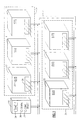
- a network control device 10 is connected to HVAC devices 12, 14, 16, 18, 20 and 22 via a communication bus 24.
- the communication bus 24 is preferably a two wire bus requiring an appropriate two wire connection to the bus from each HVAC device. It is to be appreciated that one or more of the HVAC devices may not be properly connected to the two wires of the communication bus 24. This could occur if the two wires of a particular two wire connection are transposed before being connected to the two wires of the communication bus 24.
- the HVAC device 12 will be located in a particular part of a building so as to provide conditioned air through a ventilated opening 26 to that particular building location.
- the HVAC devices 14 through 22 will provide conditioned air through respective ventilated openings in their particular building locations.
- These building locations are preferably grouped into different zones of controlled heating and/or cooling.
- HVAC devices 12, 14 and 16 are preferably located in a particular zone of heating or cooling labeled 28.
- the locations of HVAC devices 18, 20 and 22 are similarly grouped into another zone of heating and/or cooling denoted as zone 30.
- the physical locations of each HVAC device within its respective zone is available to a person wishing to check these particular HVAC devices.
- Each HVAC device is seen to include a panel of light emitting diodes (LEDs) such as the LED panel 32 for HVAC device 12.
- LEDs light emitting diodes
- Each of these LED panels is of a sufficient size and brilliance to be easily noted by one visually checking the panels of these devices in the locations wherein the HVAC devices have been installed.
- Zone control information for each HVAC control device connected to the communication bus 24 is normally provided by the network control device 10.
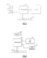
- the network control device 10 is seen to include a display 34 as well as a config button 36 and a zone select button 38.
- a person operating the network control device 10 can cause a configuration routine to be executed upon depression of the config button 36.
- the configuration routine will be performed for the particular zone displayed on the display panel 34. The particular zone is selected by depressing the zone select button 38.
- a processor 40 within the network control device is operative to receive or transmit information on the communication bus 24.
- the processor is also responsive to a config button circuit 42 and a zone select button circuit 44.
- the processor 40 is also operative to send particular messages to the display panel 34 for viewing by a person wishing to note the status of the network control device.
- the HVAC device 12 is seen to include a processor 46 having a memory 48 associated therewith.
- the processor 46 is operative to receive messages over the communication bus 24 and store the messages in a memory 48 for further analysis.
- the processor 46 is also connected to the LED control panel 32 as well as to an HVAC control circuit 50 which normally controls the local operation of the heating, ventilating and air conditioning functions performed by the HVAC device 12.
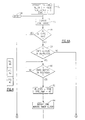
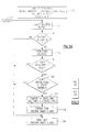
- This software begins with a step 52 wherein certain software variables are first initialized any time the processor 40 is initially powered up.
- a software variable IN_CNFG is set equal to false whereas a software variable NUM_ZONES is set equal to two and a software variable ZONE is set equal to one.
- the IN_CNFG variable is an indication as to whether or not the processor 40 is in a configuration mode or not.
- the NUM_ZONES variable is indicative of the number of zones present on the communication network of Figure 1. As has been previously noted, there are two zones illustrated in Figure 1.
- the ZONE variable is used as an identifier of one particular zone in Figure 1. For instance, the zone value of one indicates the zone 28 whereas a zone value of two identifies zone 30 in Figure 1.
- the processor 40 Upon initializing the above variables, the processor 40 proceeds to a step 54 and authorizes the display of the present value of the ZONE variable on display 34. This provides an indication to anyone viewing the display 34 as to which of the zones on the communication bus is currently available for the possible execution of the configuration routine of Figures 4A through 4D.
- the processor 40 proceeds from step 54 to a step 56 and inquires as to whether the IN_CNFG variable is equal to true. Since this variable will have initially been set equal to false, the processor will proceed to a step 58 and inquire as to whether the config button 36 is depressed. This will be accomplished by checking the status of the config button circuit 42 in Figure 2.
- the processor 40 will proceed to a step 60 and inquire as to whether the config button 36 has thereafter been released. It is to be noted that the processor will continue to inquire as to whether the config button 36 has been released by continuing to loop back through the no path until the config button circuit 42 indicates such a release of the config button. At this time, the processor 40 will proceed to a step 62 and set the IN_CNFG variable equal to true. The processor will also set a variable TEST_TIME equal to 60. The IN_CNFG variable being set equal to true will be an indication that the network control device has been asked to proceed to a configuration mode. The TEST_TIME variable of 60 will be used hereinafter to set up a particular time in which a verification test is to be performed during the configuration mode.
- the processor 40 now proceeds to initiate a one minute timer clock in a step 64.
- the one minute timer clock will preferably be a clock routine which counts up to one minute.
- the clock routine value can be read at any point in time by the processor 40 executing the program of Figures 4A through 4C.
- the processor next proceeds in a step 66 to set certain variables equal to particular values in preparation for sending a message to each HVAC device on the communication bus 24.
- the first variable MSG_ TYPE is set equal to a particular verify code. This code will have particular significance to the HVAC devices receiving the message.
- the processor 40 will also set CNFG_TIME equal to zero.
- variable CHECK_CNFG will be set equal to true whereas the variable DESTN_ADDR will be set equal to the present value of the ZONE variable, which is one.
- the processor 40 will proceed to step 68 and prepare a "verify" message for transmittal to the HVAC devices 12 through 22.
- this message will include the values of the variables discussed in step 66. It is to be appreciated that these values will preferably appear in various fields of information in the particular message.
- the first field of information may be an encoded byte set aside for identifying the type of message, which would be the binary coding that would be interpreted by the receiving device as an indication of a verify message.
- CNFG_TIME CHECK_CNFG
- DESTN_ADDR DESTN_ADDR
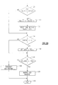
- the processor 40 proceeds after having sent the verify message in step 70 to a step 72 to inquire as to whether the config button 36 is again depressed. Assuming that the config button 36 has not been depressed, the processor will proceed to a step 74 and read the one minute timer clock previously initiated in step 64. The processor inquires whether one minute has elapsed on the minute timer clock 76. In the event that one minute has elapsed, the processor proceeds in a step 78 to reset the one minute timer clock before setting the variable TEST_TIME equal to test time minus one. Since test time was initially set equal to sixty in step 62, the test time will be decremented to fifty-nine following expiration of the first one minute.
- step 76 it is to be noted that in the event that the one minute timer clock has not expired the processor will proceed along the no path out of step 76 to a step 82, which will also be encountered immediately by the processor proceeding out of step 80.
- step 82 the processor inquires whether test time is equal to zero. In the event that the value of the TEST_TIME variable is not yet zero, the processor will proceed to step 84 and inquire as to whether the zone select button 38 has been depressed. In the event that the zone select button 38 has been depressed, the processor will proceed to a step 86 and inquire as to whether the zone select button 38 has been released. The processor will merely loop around step 86 until such action is noted.
- the zone select button 38 will normally have been depressed and thereafter released when a person operating the zone select button wishes to change the zone to be configured.
- the processor will proceed to step 88 and increment the value of the ZONE variable by one.
- the processor will also set the TEST_TIME variable equal to sixty.
- the processor next proceeds to reset the one minute timer clock so as to allow the timer clock to again begin to clock out one minute of time.
- the processor proceeds from step 90 to a step 92 and inquires as to whether the value of the zone variable is greater than NUM_ZONES. It will be remembered that NUM_ZONES is equal to two. In the event that the value of ZONE is two, the processor will proceed along the no path to an exit step 94. Referring again to step 92, in the event that the value ZONE is greater than two, the processor will proceed to a step 96 and reset the value of zone to one before exiting in exit step 94.
- the processor will proceed to execute a number of other functions for which it has been programmed before again returning to the entry point of the software program of Figures 4A through 4C denoted as step 100.
- the processor will display the present value of the ZONE variable in step 54.
- the present value of the ZONE variable will be two when the ZONE variable has been so incremented in a step 88 following a noted depression and release of the zone select button 38 in steps 84 and 86.
- very little real time will have elapsed between exiting the software of Figures 4A through 4C and the next execution of the software. There will hence be no perceptible delay in the display of the zone currently being subject to the configuration process.
- step 56 The processor will again check for whether the IN_CNFG variable is equal to true in step 56. This value should still be true as a result of having been previously set equal to true in step 62 when the config button 36 was first noted as being depressed and released. The processor will hence exit from step 56 along the yes path to step 66. Referring to step 66, the processor will now define values for the denoted variables MSG_TYPE, CNFG_TIME, CHECK_CNFG and DESTN_ADDR. It is to be noted that in this particular case the DESTN_ADDR will be equal to a zone value of two rather than a zone value of one.
- the processor proceeds in step 68 to prepare a verify message including the aforementioned variables and to send such a verify message over the communication bus 24 in step 70.
- this particular verify message will be noted for further processing in the HVAC devices 18 through 22, which comprise zone two.
- the processor proceeds again to step 72 and inquires as to whether the config button 36 has been depressed. It is to be appreciated that this button will not usually be depressed for several minutes since the person originally depressing the button will want to visually check the HVAC devices receiving and processing the verify message. This will mean that the processor will be proceeding through steps 74, 76, 78 and 80 to decrement the value of test time each time the one minute timer clock has elapsed. As long as the test time has not been decremented to zero, the processor will proceed to inquire as to whether the zone select button has been depressed. The zone select button 38 will normally not be so depressed prompting the processor to proceed along the no path out of step 38 to the exit step 94.
- test time may be decremented to zero prompting the processor to exit from step 82 via the yes path to a step 102 wherein IN_CNFG will be set equal to false before proceeding to exit step 94.
- the config button 36 may be depressed at some point in time before the test time is equal to zero. This will be detected in a step 72 prompting the processor to proceed to a step 104 to inquire whether the config button 36 has been released. When the config button is released, the processor will proceed to step 102 and again set IN_CNFG equal to false.
- the IN_CNFG variable will be set equal to false either as a result of the test time having expired or the processor noting that the config button 36 has been depressed and released. Following the occurrence of either event, the processor will in the next execution of the software of Figures 4A through 4C note in step 56 that the IN_CNFG variable is false. This will prompt the processor to inquire whether the config button 36 has been depressed in step 58. In the event that the config button 36 has not been depressed, the processor will proceed out of step 58 to step 102 and again set the IN_CNFG variable false before exiting in step 94. The processor will thereafter continuously execute steps 58, 100, 54, 56, 102 and 94 until such time as the config button 36 is depressed. This will suspend any further transmittal of verification messages to the respective zones until the config button 36 is again depressed.
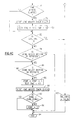
- the software executable by the processor within each HVAC device connected to the communication bus 24 begins with an initialization step 110 wherein a device address is defined.
- the device address will preferably be a particular zone value.
- the HVAC devices 12, 14 and 16 will each have a device address of one whereas the HVAC devices 18, 20 and 22 will each have a zone address of two.
- the appropriate device address will have been previously stored in the particular memory associated with the processor of each HVAC device.
- memory 48 will contain the assigned value of one since the particular HVAC device 12 is in zone one.
- the memory 48 within the HVAC device 12 will also have stored a value for a variable DO_CNFG equal to false.
- the memory 48 will have a stored value for a TIMEOUT variable that is equal to eleven.
- the processor will proceed to a step 112 and check a message buffer. It is to be appreciated that the processor 46 will in normal operation read any message on the communication bus 24 and store the same in a message buffer within memory 48. The processor will subsequently check the message buffer in step 112 while executing the process of Figure 5. The processor will proceed from step 112 to a step 114 and inquire whether a message has been detected in the message buffer. In the event that a message has been detected, the processor will proceed along the yes path to a step 116 and download the message. The process will next inquire in a step 118 as to whether the MSG_TYPE field within the downloaded message has a binary coding indicating a verify message.
- the processor proceeds to a step 120 and inquires whether the field set aside in the message for DESTN_ADDR equals the particular device address assigned to the particular HVAC device. In the event that the DESTN_ADDR is for instance a one, the processor 46 within the HVAC device 12 would proceed along the yes path to a step 122. Referring to step 122, a TIMEOUT variable is set equal to the value of the CNFG_TIME field of the downloaded message. It will be remembered that this value is zero in the message sent by the network control device 10. The processor next will also set the CO_CNFG variable equal to the value of the field in the downloaded message set aside for CHECK_CNFG.
- the processor 46 proceeds from step 122 to a step 124 and initiates a one second timer clock.
- the processor proceeds to a step 126 and reads the one second timer clock and inquires as to whether one second has elapsed in step 128. In the event that one second has elapsed, the processor 46 proceeds to a step 130 and increments the value of the TIMEOUT variable by one. It will be remembered that the TIMEOUT variable is set equal to zero in step 122 when a verify message has been received. This will prompt the TIMEOUT variable to initially be set equal to one in step 130.
- the processor next proceeds to a step 132 and resets the one second timer clock before proceeding to step 134 to inquire as to whether the TIMEOUT value is greater than ten. Referring to step 128, in the event that the one second timer clock has not elapsed, the processor will also proceed to step 134. If the TIMEOUT variable is equal to ten or less, the processor will proceed along the no path out of step 134 to a step 136 and inquire whether the DO_CNFG variable is true. Since the DO_CNFG variable will have been set equal to true in step 122, the processor will proceed along the yes path to a step 138. Referring to step 138, the processor is operative to initiate an LED routine.
- This routine will preferably send signals each one-half second to the respective LED panel associated with the processor executing the process of Figures 5A and 5B.
- the routine will cause the LED panel 32 to blink or flash every one-half second. This blinking or flashing of the LED panel in response to the LED routine initiated in step 138 will continue until such time as terminated.
- the processor will proceed from initiating the LED routine in step 138 to an exit step 140.
- the processor executing the particular software program of Figures 5A and 5B will execute various other programs normally performed by the processor for the particular HVAC device. This would, for instance, include the checking and monitoring of the HVAC control circuit for the device.
- the processor will proceed to the entry step 142 in Figure 5A and again check the message buffer for any new messages. Assuming that no new message has been received, the processor will proceed to step 126 and read the one second timer clock. In the event that one second has elapsed, the processor will proceed to increment the value of the TIMEOUT variable in step 130 and reset the one second timer clock once again in step 132. The processor will proceed to inquire as to whether the TIMEOUT variable is greater than ten in step 134. In the event that the TIMEOUT variable is ten or less, the processor will proceed to set the DO_CNFG variable equal to true in step 136 before again initiating the LED routine 138 and exiting in step 140. It is to be appreciated that this step of again initiating the LED routine will have no effect on an LED routine that is already activated.
- steps 112 through 128 will at some time result in the TIMEOUT variable being incremented to a value greater than ten.
- the processor will note in step 134 that the TIMEOUT variable is greater than ten thus prompting the processor to set the DO_CNFG variable equal to false in step 142.
- the processor now proceeds through step 136 and exits along the no path to a step 144, which terminates the LED routine. This will cause the processor 46 to, for instance, terminate any further flashing or blinking of the LED panel 32.
- the processor proceeds to the exit step 140 following termination of the LED routine.
- the LED routine initiated in step 138 will be terminated at the expiration of a ten second TIMEOUT period unless the particular processor in the HVAC device has received another verification message from the network control device 10.
- a verification message will normally be sent to each HVAC device as a result of the processor proceeding through step 56 to steps 66, 68 and 70 when the processor 40 is in a configuration mode.
- the network control device 10 is operative to send appropriate verification messages to a prescribed zone of HVAC devices connected to the communication bus 24.
- the resulting verification message will be sent on a timely basis to each such HVAC control device so as to allow the HVAC control device to continuously trigger the flashing or blinking of an LED display until such time as a different zone has been selected or a decision has been made to exit the configuration process.
- the transmittal of a verification message will also cease in the event that the next zone button 38 has not been depressed within one hour. This will result in the LED display of an HVAC device possibly flashing continuously for a maximum of one hour. This will allow a person wishing to check the individual HVAC devices at their respective locations up to one hour to confirm appropriately flashing LED panels.
- Any HVAC devices in a zone that are not flashing will be thereafter physically checked to ascertain why their LED panels are not flashing.
- This physical check will include, for instance, a checking of the two wire connections to the communication bus 24 to ascertain whether any of these connections have been transposed.
Landscapes
- Engineering & Computer Science (AREA)
- Physics & Mathematics (AREA)
- General Physics & Mathematics (AREA)
- Automation & Control Theory (AREA)
- Chemical & Material Sciences (AREA)
- Combustion & Propulsion (AREA)
- Mechanical Engineering (AREA)
- General Engineering & Computer Science (AREA)
- Air Conditioning Control Device (AREA)
- Selective Calling Equipment (AREA)
- Small-Scale Networks (AREA)
Claims (19)
- Verfahren zum Verifizieren der Betriebsfähigkeit von mindestens einer HVAC-Vorrichtung in einem Kommunikationsnetzwerk (24), wobei das Verfahren folgende Schritte aufweist:Senden einer Nachricht von einer Netzwerkkontrollvorrichtung (10) an die HVAC-Vorrichtung (12, 14, 16, 18, 20, 22), wobei die Nachricht eine Information zum Auffordern der HVAC-Vorrichtung, eine sichtbare Anzeige (32) an der HVAC-Vorrichtung zu starten, falls die Nachricht von der HVAC-Vorrichtung erfolgreich verarbeitet wird, aufweist;Empfangen der Nachricht von der Netzwerkkontrollvorrichtung (10) an der HVAC-Vorrichtung und danach Verarbeiten der Information zum Auffordern der HVAC-Vorrichtung, eine sichtbare Anzeige zu starten; undautomatisches Starten einer sichtbaren Anzeige auf der HVAC-Vorrichtung, wenn die Nachricht empfangen wird und durch die HVAC-Vorrichtung verarbeitet wird, wobei die sichtbare Anzeige einfach durch eine Person wahrgenommen werden kann, die wünscht, den physikalischen Ort zu prüfen, an dem die HVAC-Vorrichtung installiert wurde.
- Verfahren nach Anspruch 1, wobei der Schritt des Sendens einer Nachricht von der Netzwerkkontrollvorrichtung Folgendes aufweist:Vermerken in der Netzwerkkontrollvorrichtung, wann eine Wahl getroffen wurde, die Nachricht zu senden; undwiederholtes Übertragen der Nachricht an die HVAC-Vorrichtung, bis zu einem derartigen Zeitpunkt, zu dem eine Wahl getroffen wurde, die Übertragung der Nachricht zu beenden.
- Verfahren nach Anspruch 2, wobei der Schritt des Vermerkens, wann eine Wahl getroffen wurde, die Nachricht zu senden, folgenden Schritt aufweist:Vermerken des Zustands einer Schaltung in der Netzwerkkontrollvorrichtung, welche anzeigt, ob ein Schalter an der Netzwerkkontrollvorrichtung gedrückt wurde oder losgelassen wurde.
- Verfahren nach Anspruch 2, wobei der Schritt des wiederholten Übertragens der Nachricht an die HVAC-Vorrichtung, bis zu einem derartigen Zeitpunkt, zu dem eine Wahl getroffen wurde, die Nachricht zu beenden, folgende Schritte aufweist:Vermerken des Zustands einer Schaltung in der Netzwerkkontrollvorrichtung, welche anzeigt, ob ein Schalter auf der Netzwerkkontrollvorrichtung gedrückt wurde oder losgelassen wurde;Beenden der wiederholten Übertragung der Nachricht, wenn der Zustand der Schaltung anzeigt, dass der Schalter gedrückt wurde oder losgelassen wurde.
- Verfahren nach Anspruch 4, das ferner folgenden Schritt aufweist:Beenden der wiederholten Übertragung der Nachricht an die HVAC-Vorrichtung nachdem eine vorbestimmte Zeitspanne abgelaufen ist, die sich an den Übertragungsbeginn der Nachricht von der Netzwerkkontrollvorrichtung ausschließt.
- Verfahren nach Anspruch 2, wobei der Schritt des Startens einer sichtbaren Anzeige auf der HVAC-Vorrichtung Folgendes aufweist:automatisches Starten einer sichtbaren Anzeige, das dem Verarbeiten der Nachricht von der Netzwerkkontrollvorrichtung folgt; undSetzen einer vorbestimmten Zeitdauer für eine sichtbare Anzeige, während welcher die sichtbare Anzeige ohne Empfang einer weiteren übertragenen Nachricht von der Netzwerkkontrollvorrichtung weiter auftritt, wobei die vorbestimmte Zeitdauer für eine sichtbare Anzeige länger ist als die maximale Zeitspanne, welche zwischen einer wiederholten Übertragung der Nachricht von der Netzwerkkontrollvorrichtung ablaufen kann.
- Verfahren nach Anspruch 1, wobei der Schritt des automatischen Startens einer sichtbaren Anzeige auf der HVAC-Vorrichtung Folgendes aufweist:automatisches Starten einer sichtbaren Anzeige, das dem Verarbeiten der Nachricht von der Netzwerkkontrollvörrichtung folgt; undSetzen einer vorbestimmten Zeitdauer für eine sichtbare Anzeige, während welcher die sichtbare Anzeige ohne Empfang einer weiteren Nachricht von der Netzwerkkontrollvorrichtung weiter auftritt.
- Verfahren nach Anspruch 6 oder 7, wobei der Schritt des Startens einer sichtbaren Anzeige folgenden Schritt aufweist:intermittiertes Anstoßen des Aufleuchtens eine Feldes von Leuchtdioden auf der HVAC-Vorrichtung, um so ein sichtbares Blinken des Feldes von Leuchtdioden zu erzeugen.
- Verfahren nach Anspruch 1, wobei die von der Netzwerkkontrollvorrichtung gesendete Nachricht eine bestimmte Kennung bezüglich des Typs der gesendeten Nachricht aufweist und wobei der Schritt des Empfangens der Nachricht von der Netzwerkkontrollvorrichtung an der HVAC-Vorrichtung und des Verarbeitens der Information danach zum Auffordern der HVAC-Vorrichtung eine sichtbare Anzeige zu starten, folgende Schritte aufweist:wobei eine sichtbare Anzeige nur gestartet wird, wenn die empfangene Nachricht die bestimmte Kennung bezüglich des Nachrichtentyps enthält.Empfangen der Nachricht an der HVAC-Kontrollvorrichtung; undÜberprüfen der empfangenen Nachricht nach der bestimmten Kennung bezüglich des Nachrichtentyps;
- System zum Verifizieren der Betriebsfähigkeit einer Mehrzahl von HVAC-Vorrichtungen (12, 14, 16, 18, 20, 22), die mit mindestens einer Kontrollvorrichtung (10) mittels eines Kommunikationsnetzwerks (24) in Kommunikation stehen; wobei das System aufweist:- einen Prozessor (40) in der Kontrollvorrichtung (10), welcher eine Nachricht über das Netzwerk (24) an jede aus der Mehrzahl von HVAC-Vorrichtungen sendet, wobei die Nachricht eine Information aufweist, die eine HVAC-Vorrichtung auffordert, eine sichtbare Anzeige (32) zu starten, falls die Nachricht von dieser HVAC-Vorrichtung erfolgreich verarbeitet wird; undeine Mehrzahl von HVAC-Vorrichtungs-Prozessoren (46) zum Verarbeiten der Nachricht, die von der Steuervorrichtung (10) empfangen wurde, wobei jeder der HVAC-Vorrichtungs-Prozessoren eine Einrichtung (32) zum automatischen Starten einer sichtbaren Anzeige auf einem Anzeigefeld (32), das dem HVAC-Vorrichtungs-Prozessor zugeordnet ist, in Reaktion auf ein Lesen der Information in der Nachricht aufweist.
- System nach Anspruch 10, wobei der Prozessor in der Steuervorrichtung aufweist:eine Einrichtung zum Vermerken, wann eine Wahl getroffen wurde, die Nachricht zu senden; undeine Einrichtung zum wiederholten Übertragen der Nachricht an die HVAC-Vorrichtung, bis zu einem derartigen Zeitpunkt, an dem eine Wahl getroffen wurde, die Übertragung der Nachricht zu beenden.
- System nach Anspruch 11, wobei die Einrichtung zum Vermerken, wann eine Wahl getroffen wurde, die Nachricht zu senden, aufweist:eine Einrichtung zum Vermerken des Zustands einer Schaltung in der Kontrollvorrichtung, welche anzeigt, ob ein Schalter an der Steuervorrichtung gedrückt wurde oder losgelassen wurde.
- System nach Anspruch 12, wobei die Einrichtung zur wiederholten Übertragung der Nachricht an die HVAC-Vorrichtung, bis zu einem derartigen Zeitpunkt, zu dem eine Wahl getroffen wurde, die Nachrichtenübertragung zu beenden, aufweist:eine Einrichtung zum Vermerken des Zustands einer Schaltung in der Kontrollvorrichtung, welche anzeigt, ob ein Schalter an der kontrollvorrichtung gedrückt wurde oder losgelassen wurde; undeine Einrichtung zum Beenden der wiederholten Übertragung der Nachricht, wenn der Zustand der Schaltung anzeigt, dass der Schalter gedrückt wurde oder losgelassen wurde.
- System nach Anspruch 13, wobei der Prozessor in der Kontrollvorrichtung ferner aufweist:eine Einrichtung zum Beenden der wiederholten Übertragung der Nachricht an die HVAC-Vorrichtungen, nachdem eine vorbestimmte Zeitspanne abgelaufen ist, die sich an den Übertragungsbeginn der Nachricht an die HVAC-Vorrichtungen anschließt.
- System nach Anspruch 11, wobei jeder HVAC-Vorrichtungs-prozessor ferner aufweist:eine Vorrichtung zum Setzen einer vorbestimmten Zeitspanne, während welcher die sichtbare Anzeige auf dem Anzeigefeld andauernd auftritt, die dem HVAC-Vorrichtungs-Prozessor zugeordnet ist, ohne dass die HVAC-Vorrichtung irgendwelche weitere wiederholt übertragene Nachrichten von der Steuervorrichtung empfangen hat.
- System nach Anspruch 15, wobei die Anzeigefelder, die jedem aus der Mehrzahl von HVAC-Vorrichtungs-Prozessoren zugeordnet sind, ein Feld aus Leuchtdioden sind, und die Einrichtung zum Beginnen einer sichtbaren Anzeige auf den Anzeigefeldern aufweist:eine Einrichtung zum intermittierten Anstoßen des Aufleuchtens des Feldes aus Leuchtdioden, um ein sichtbares Blinken des Feldes aus Leuchtdioden, zu erzeugen.
- System nach Anspruch 10, wobei jeder HVAC-Vorrichtungs-Prozessor ferner aufweist:eine Einrichtung zum Setzen einer vorbestimmten Zeitspanne, während welcher die sichtbare Anzeige auf dem Anzeigefeld, das dem entsprechenden HVAC-Vorrichtungs-Prozessor zugeordnet ist, andauernd auftritt; undeine Einrichtung zum Beenden der sichtbaren Anzeige auf dem Anzeigefeld, falls eine weitere Nachricht von der Kontrollvorrichtung nicht empfangen wurde, bevor die vorbestimmte Zeitspanne abläuft.
- System nach Anspruch 17, wobei die Anzeigefelder, die jedem aus der Mehrzahl von HVAC-Vorrichtungs-Prozessoren zugeordnet sind, ein Feld aus Leuchtdioden sind, und die Einrichtung zum automatischen Beginnen einer sichtbaren Anzeige auf den Anzeigefeldern aufweist:eine Einrichtung zum intermittierten Anstoßen des sichtbaren Blinkens auf dem Feld aus Leuchtdioden.
- System nach Anspruch 10, wobei die durch den Prozessor in der Kontrollvorrichtung gesendete Nachricht eine Kennung des bestimmten Typs von gesendeter Nachricht aufweist und wobei jede der Einrichtungen zum automatischen Starten von sichtbaren Anzeigen auf Anzeigetafeln, die jedem aus der Mehrzahl von HVAC-Vorrichtungs-Prozessoren zugeordnet sind, aufweist:eine Einrichtung zum Vermerken, ob eine von der Kontrollvorrichtung empfangene Nachricht die Kennung des bestimmten Nachrichtentyps enthält; undeine Einrichtung zum Starten einer sichtbaren Anzeige auf dem Anzeigefeld, das dem HVAC-Vorrichtungs-Prozessor zugeordnet ist, wenn die empfangene Nachricht die Kennung des bestimmten Nachrichtentyps enthält.
Priority Applications (1)
| Application Number | Priority Date | Filing Date | Title |
|---|---|---|---|
| SI9730558T SI0838739T1 (en) | 1996-10-25 | 1997-10-08 | HVAC network verification system |
Applications Claiming Priority (2)
| Application Number | Priority Date | Filing Date | Title |
|---|---|---|---|
| US08/738,157 US6535138B1 (en) | 1996-10-25 | 1996-10-25 | HVAC network verification system |
| US738157 | 1996-10-25 |
Publications (2)
| Publication Number | Publication Date |
|---|---|
| EP0838739A1 EP0838739A1 (de) | 1998-04-29 |
| EP0838739B1 true EP0838739B1 (de) | 2003-04-23 |
Family
ID=24966805
Family Applications (1)
| Application Number | Title | Priority Date | Filing Date |
|---|---|---|---|
| EP97307958A Expired - Lifetime EP0838739B1 (de) | 1996-10-25 | 1997-10-08 | System zur Prüfung eines Heizungs-, Lüftungs- und Klimaanlagenetzes |
Country Status (18)
| Country | Link |
|---|---|
| US (1) | US6535138B1 (de) |
| EP (1) | EP0838739B1 (de) |
| AR (1) | AR008507A1 (de) |
| AT (1) | ATE238575T1 (de) |
| BG (1) | BG101988A (de) |
| BR (1) | BR9705130A (de) |
| CZ (1) | CZ294320B6 (de) |
| DE (1) | DE69721181T2 (de) |
| DK (1) | DK0838739T3 (de) |
| ES (1) | ES2192654T3 (de) |
| HR (1) | HRP970568A2 (de) |
| HU (1) | HUP9701705A3 (de) |
| NO (1) | NO319187B1 (de) |
| PL (1) | PL188445B1 (de) |
| PT (1) | PT838739E (de) |
| RO (1) | RO118231B1 (de) |
| RU (1) | RU2216782C2 (de) |
| SI (1) | SI0838739T1 (de) |
Cited By (1)
| Publication number | Priority date | Publication date | Assignee | Title |
|---|---|---|---|---|
| US6799101B2 (en) | 2002-12-05 | 2004-09-28 | Wabco Gmbh & Co. Ohg | Method for programming flash EEPROMS in microprocessor-equipped vehicle control electronics |
Families Citing this family (63)
| Publication number | Priority date | Publication date | Assignee | Title |
|---|---|---|---|---|
| US20040111500A1 (en) * | 2002-12-10 | 2004-06-10 | York International Corporation | System and method for commissioning a unit into a networked control system |
| US6955302B2 (en) * | 2003-11-13 | 2005-10-18 | York International Corporation | Remote monitoring diagnostics |
| US7212887B2 (en) * | 2004-01-20 | 2007-05-01 | Carrier Corporation | Service and diagnostic tool for HVAC systems |
| US7308384B2 (en) * | 2004-01-20 | 2007-12-11 | Carrier Corporation | Ordered record of system-wide fault in an HVAC system |
| EP1659462B9 (de) * | 2004-11-19 | 2009-11-25 | ebm-papst Mulfingen GmbH & Co.KG | Verfahren zur Inbetriebnahme einer elektrischen Anlage |
| US7448435B2 (en) * | 2005-02-23 | 2008-11-11 | Emerson Electric Co. | System and method for controlling a multi-zone heating or cooling system |
| US20060198208A1 (en) * | 2005-03-07 | 2006-09-07 | Lantronix, Inc. | Publicasting systems and methods |
| US7400240B2 (en) * | 2005-08-16 | 2008-07-15 | Honeywell International, Inc. | Systems and methods of deterministic annunciation |
| US7451606B2 (en) * | 2006-01-06 | 2008-11-18 | Johnson Controls Technology Company | HVAC system analysis tool |
| US20070221741A1 (en) * | 2006-03-27 | 2007-09-27 | Ranco Incorporated Of Delaware | Connector terminal system and wiring method for thermostat |
| DE102007055613B4 (de) * | 2007-11-20 | 2013-11-14 | Phoenix Contact Gmbh & Co. Kg | Automatisierungssystem zum Kennzeichnen eines Kanals innerhalb eines Busteilnehmers |
| US8295981B2 (en) | 2008-10-27 | 2012-10-23 | Lennox Industries Inc. | Device commissioning in a heating, ventilation and air conditioning network |
| US8655490B2 (en) | 2008-10-27 | 2014-02-18 | Lennox Industries, Inc. | System and method of use for a user interface dashboard of a heating, ventilation and air conditioning network |
| US8694164B2 (en) | 2008-10-27 | 2014-04-08 | Lennox Industries, Inc. | Interactive user guidance interface for a heating, ventilation and air conditioning system |
| US8543243B2 (en) | 2008-10-27 | 2013-09-24 | Lennox Industries, Inc. | System and method of use for a user interface dashboard of a heating, ventilation and air conditioning network |
| US8977794B2 (en) | 2008-10-27 | 2015-03-10 | Lennox Industries, Inc. | Communication protocol system and method for a distributed-architecture heating, ventilation and air conditioning network |
| US9377768B2 (en) | 2008-10-27 | 2016-06-28 | Lennox Industries Inc. | Memory recovery scheme and data structure in a heating, ventilation and air conditioning network |
| US8352080B2 (en) | 2008-10-27 | 2013-01-08 | Lennox Industries Inc. | Communication protocol system and method for a distributed-architecture heating, ventilation and air conditioning network |
| US9152155B2 (en) | 2008-10-27 | 2015-10-06 | Lennox Industries Inc. | Device abstraction system and method for a distributed-architecture heating, ventilation and air conditioning system |
| US8774210B2 (en) | 2008-10-27 | 2014-07-08 | Lennox Industries, Inc. | Communication protocol system and method for a distributed-architecture heating, ventilation and air conditioning network |
| US8855825B2 (en) | 2008-10-27 | 2014-10-07 | Lennox Industries Inc. | Device abstraction system and method for a distributed-architecture heating, ventilation and air conditioning system |
| US9261888B2 (en) | 2008-10-27 | 2016-02-16 | Lennox Industries Inc. | System and method of use for a user interface dashboard of a heating, ventilation and air conditioning network |
| US8725298B2 (en) | 2008-10-27 | 2014-05-13 | Lennox Industries, Inc. | Alarm and diagnostics system and method for a distributed architecture heating, ventilation and conditioning network |
| US9632490B2 (en) | 2008-10-27 | 2017-04-25 | Lennox Industries Inc. | System and method for zoning a distributed architecture heating, ventilation and air conditioning network |
| US8762666B2 (en) | 2008-10-27 | 2014-06-24 | Lennox Industries, Inc. | Backup and restoration of operation control data in a heating, ventilation and air conditioning network |
| US8452456B2 (en) | 2008-10-27 | 2013-05-28 | Lennox Industries Inc. | System and method of use for a user interface dashboard of a heating, ventilation and air conditioning network |
| US8661165B2 (en) | 2008-10-27 | 2014-02-25 | Lennox Industries, Inc. | Device abstraction system and method for a distributed architecture heating, ventilation and air conditioning system |
| US8433446B2 (en) | 2008-10-27 | 2013-04-30 | Lennox Industries, Inc. | Alarm and diagnostics system and method for a distributed-architecture heating, ventilation and air conditioning network |
| US8788100B2 (en) | 2008-10-27 | 2014-07-22 | Lennox Industries Inc. | System and method for zoning a distributed-architecture heating, ventilation and air conditioning network |
| US9651925B2 (en) * | 2008-10-27 | 2017-05-16 | Lennox Industries Inc. | System and method for zoning a distributed-architecture heating, ventilation and air conditioning network |
| US8892797B2 (en) | 2008-10-27 | 2014-11-18 | Lennox Industries Inc. | Communication protocol system and method for a distributed-architecture heating, ventilation and air conditioning network |
| US8560125B2 (en) | 2008-10-27 | 2013-10-15 | Lennox Industries | Communication protocol system and method for a distributed-architecture heating, ventilation and air conditioning network |
| US8437877B2 (en) | 2008-10-27 | 2013-05-07 | Lennox Industries Inc. | System recovery in a heating, ventilation and air conditioning network |
| US9432208B2 (en) | 2008-10-27 | 2016-08-30 | Lennox Industries Inc. | Device abstraction system and method for a distributed architecture heating, ventilation and air conditioning system |
| US8463442B2 (en) | 2008-10-27 | 2013-06-11 | Lennox Industries, Inc. | Alarm and diagnostics system and method for a distributed architecture heating, ventilation and air conditioning network |
| US8600559B2 (en) | 2008-10-27 | 2013-12-03 | Lennox Industries Inc. | Method of controlling equipment in a heating, ventilation and air conditioning network |
| US8442693B2 (en) | 2008-10-27 | 2013-05-14 | Lennox Industries, Inc. | System and method of use for a user interface dashboard of a heating, ventilation and air conditioning network |
| US8655491B2 (en) | 2008-10-27 | 2014-02-18 | Lennox Industries Inc. | Alarm and diagnostics system and method for a distributed architecture heating, ventilation and air conditioning network |
| US9678486B2 (en) | 2008-10-27 | 2017-06-13 | Lennox Industries Inc. | Device abstraction system and method for a distributed-architecture heating, ventilation and air conditioning system |
| US8239066B2 (en) | 2008-10-27 | 2012-08-07 | Lennox Industries Inc. | System and method of use for a user interface dashboard of a heating, ventilation and air conditioning network |
| US8798796B2 (en) | 2008-10-27 | 2014-08-05 | Lennox Industries Inc. | General control techniques in a heating, ventilation and air conditioning network |
| US8437878B2 (en) | 2008-10-27 | 2013-05-07 | Lennox Industries Inc. | Alarm and diagnostics system and method for a distributed architecture heating, ventilation and air conditioning network |
| US9325517B2 (en) | 2008-10-27 | 2016-04-26 | Lennox Industries Inc. | Device abstraction system and method for a distributed-architecture heating, ventilation and air conditioning system |
| US9268345B2 (en) | 2008-10-27 | 2016-02-23 | Lennox Industries Inc. | System and method of use for a user interface dashboard of a heating, ventilation and air conditioning network |
| US8874815B2 (en) | 2008-10-27 | 2014-10-28 | Lennox Industries, Inc. | Communication protocol system and method for a distributed architecture heating, ventilation and air conditioning network |
| US8615326B2 (en) | 2008-10-27 | 2013-12-24 | Lennox Industries Inc. | System and method of use for a user interface dashboard of a heating, ventilation and air conditioning network |
| US8802981B2 (en) | 2008-10-27 | 2014-08-12 | Lennox Industries Inc. | Flush wall mount thermostat and in-set mounting plate for a heating, ventilation and air conditioning system |
| US8548630B2 (en) | 2008-10-27 | 2013-10-01 | Lennox Industries, Inc. | Alarm and diagnostics system and method for a distributed-architecture heating, ventilation and air conditioning network |
| US8564400B2 (en) | 2008-10-27 | 2013-10-22 | Lennox Industries, Inc. | Communication protocol system and method for a distributed-architecture heating, ventilation and air conditioning network |
| US8994539B2 (en) | 2008-10-27 | 2015-03-31 | Lennox Industries, Inc. | Alarm and diagnostics system and method for a distributed-architecture heating, ventilation and air conditioning network |
| US8463443B2 (en) | 2008-10-27 | 2013-06-11 | Lennox Industries, Inc. | Memory recovery scheme and data structure in a heating, ventilation and air conditioning network |
| US8452906B2 (en) | 2008-10-27 | 2013-05-28 | Lennox Industries, Inc. | Communication protocol system and method for a distributed-architecture heating, ventilation and air conditioning network |
| US8600558B2 (en) | 2008-10-27 | 2013-12-03 | Lennox Industries Inc. | System recovery in a heating, ventilation and air conditioning network |
| US8744629B2 (en) | 2008-10-27 | 2014-06-03 | Lennox Industries Inc. | System and method of use for a user interface dashboard of a heating, ventilation and air conditioning network |
| US8352081B2 (en) | 2008-10-27 | 2013-01-08 | Lennox Industries Inc. | Communication protocol system and method for a distributed-architecture heating, ventilation and air conditioning network |
| US8255086B2 (en) | 2008-10-27 | 2012-08-28 | Lennox Industries Inc. | System recovery in a heating, ventilation and air conditioning network |
| USD648642S1 (en) | 2009-10-21 | 2011-11-15 | Lennox Industries Inc. | Thin cover plate for an electronic system controller |
| USD648641S1 (en) | 2009-10-21 | 2011-11-15 | Lennox Industries Inc. | Thin cover plate for an electronic system controller |
| US8260444B2 (en) | 2010-02-17 | 2012-09-04 | Lennox Industries Inc. | Auxiliary controller of a HVAC system |
| US20130190932A1 (en) * | 2012-01-20 | 2013-07-25 | Daniel C. Schuman | System and method for operation of an hvac system to adjust ambient air temperature |
| US9874366B2 (en) | 2014-07-30 | 2018-01-23 | Research Products Corporation | System and method for adjusting fractional on-time and cycle time to compensate for weather extremes and meet ventilation requirements |
| US10908627B2 (en) | 2016-05-25 | 2021-02-02 | Alper Uzmezler | Edge analytics control devices and methods |
| RU2698467C1 (ru) * | 2018-05-03 | 2019-08-27 | Федеральное государственное унитарное предприятие Центральный научно-исследовательский институт связи ФГУП ЦНИИС | Устройство диагностирования работоспособности УПС-ТФ |
Family Cites Families (15)
| Publication number | Priority date | Publication date | Assignee | Title |
|---|---|---|---|---|
| US4497031A (en) * | 1982-07-26 | 1985-01-29 | Johnson Service Company | Direct digital control apparatus for automated monitoring and control of building systems |
| JPS62102053A (ja) | 1985-10-30 | 1987-05-12 | Nippon Telegr & Teleph Corp <Ntt> | 空調装置用信号収集変換装置の入出力状態表示方式 |
| DE3609929C1 (de) * | 1986-03-24 | 1987-09-24 | Benke Instr & Elektro Ag | Prozessanalysator-System |
| US4931948A (en) * | 1987-02-12 | 1990-06-05 | Parker Electronics, Inc. | Method and system for controlling a single zone HVAC supplying multiple zones |
| US5309146A (en) * | 1988-05-03 | 1994-05-03 | Electronic Environmental Controls Inc. | Room occupancy indicator means and method |
| US5165465A (en) * | 1988-05-03 | 1992-11-24 | Electronic Environmental Controls Inc. | Room control system |
| JPH0217348A (ja) | 1988-07-06 | 1990-01-22 | Mitsubishi Electric Corp | 空気調和機の制御装置 |
| US5086385A (en) * | 1989-01-31 | 1992-02-04 | Custom Command Systems | Expandable home automation system |
| EP0513206B1 (de) * | 1990-01-30 | 1995-04-12 | Johnson Service Company | Vernetztes betriebsmittelverwaltungssystem |
| US5198809A (en) * | 1991-02-22 | 1993-03-30 | James L. Day Co. Inc. | Hard wired programmable controller especially for heating ventilating and air conditioning (HVAC systems) |
| US5291190A (en) * | 1991-03-28 | 1994-03-01 | Combustion Engineering, Inc. | Operator interface for plant component control system |
| US5233247A (en) * | 1991-07-16 | 1993-08-03 | The United States Of America As Represented By The Secretary Of The Navy | Precision drive and speed reduction device |
| DE69212997T2 (de) | 1992-06-19 | 1997-05-28 | Euro Cp Sarl | Verfahren zur Adressierung einer Betriebseinrichtung und zur Verbindung von zwei Betriebseinrichtungen; Betriebseinrichtung und Anlage dafür |
| US5555269A (en) | 1993-10-29 | 1996-09-10 | Carrier Corporation | Error detection for HVAC systems |
| JPH08205251A (ja) | 1995-01-24 | 1996-08-09 | Nissan Shatai Co Ltd | リモコン受信装置 |
-
1996
- 1996-10-25 US US08/738,157 patent/US6535138B1/en not_active Expired - Lifetime
-
1997
- 1997-10-08 DE DE69721181T patent/DE69721181T2/de not_active Expired - Fee Related
- 1997-10-08 EP EP97307958A patent/EP0838739B1/de not_active Expired - Lifetime
- 1997-10-08 ES ES97307958T patent/ES2192654T3/es not_active Expired - Lifetime
- 1997-10-08 DK DK97307958T patent/DK0838739T3/da active
- 1997-10-08 SI SI9730558T patent/SI0838739T1/xx unknown
- 1997-10-08 AT AT97307958T patent/ATE238575T1/de not_active IP Right Cessation
- 1997-10-08 PT PT97307958T patent/PT838739E/pt unknown
- 1997-10-09 NO NO19974658A patent/NO319187B1/no unknown
- 1997-10-22 BG BG101988A patent/BG101988A/xx unknown
- 1997-10-22 HU HU9701705A patent/HUP9701705A3/hu unknown
- 1997-10-23 BR BR9705130-6A patent/BR9705130A/pt not_active Application Discontinuation
- 1997-10-23 RO RO97-01977A patent/RO118231B1/ro unknown
- 1997-10-24 CZ CZ19973397A patent/CZ294320B6/cs not_active IP Right Cessation
- 1997-10-24 AR ARP970104935A patent/AR008507A1/es unknown
- 1997-10-24 PL PL97322812A patent/PL188445B1/pl not_active IP Right Cessation
- 1997-10-24 HR HR08/738,157A patent/HRP970568A2/hr not_active Application Discontinuation
- 1997-10-24 RU RU97117469/09A patent/RU2216782C2/ru not_active IP Right Cessation
Cited By (1)
| Publication number | Priority date | Publication date | Assignee | Title |
|---|---|---|---|---|
| US6799101B2 (en) | 2002-12-05 | 2004-09-28 | Wabco Gmbh & Co. Ohg | Method for programming flash EEPROMS in microprocessor-equipped vehicle control electronics |
Also Published As
| Publication number | Publication date |
|---|---|
| ATE238575T1 (de) | 2003-05-15 |
| DE69721181T2 (de) | 2004-04-08 |
| DK0838739T3 (da) | 2003-05-19 |
| RO118231B1 (ro) | 2003-03-28 |
| HUP9701705A3 (en) | 1999-04-28 |
| DE69721181D1 (de) | 2003-05-28 |
| CZ339797A3 (cs) | 1999-01-13 |
| SI0838739T1 (en) | 2003-12-31 |
| HU9701705D0 (en) | 1997-12-29 |
| PT838739E (pt) | 2003-09-30 |
| CZ294320B6 (cs) | 2004-11-10 |
| AR008507A1 (es) | 2000-01-19 |
| HUP9701705A2 (hu) | 1998-06-29 |
| NO319187B1 (no) | 2005-06-27 |
| NO974658L (no) | 1998-04-27 |
| BR9705130A (pt) | 2001-01-16 |
| PL322812A1 (en) | 1998-04-27 |
| RU2216782C2 (ru) | 2003-11-20 |
| ES2192654T3 (es) | 2003-10-16 |
| HRP970568A2 (en) | 1998-06-30 |
| BG101988A (en) | 1998-05-29 |
| US6535138B1 (en) | 2003-03-18 |
| NO974658D0 (no) | 1997-10-09 |
| PL188445B1 (pl) | 2005-02-28 |
| EP0838739A1 (de) | 1998-04-29 |
Similar Documents
| Publication | Publication Date | Title |
|---|---|---|
| EP0838739B1 (de) | System zur Prüfung eines Heizungs-, Lüftungs- und Klimaanlagenetzes | |
| US5495722A (en) | Remote control for diagnostics of an air conditioner | |
| JP4460303B2 (ja) | 双方向対象物をペアリングする方法 | |
| US8346964B2 (en) | Multi-processor communications system incorporating prioritized messaging | |
| JP5405430B2 (ja) | 双方向対象物の中からあるグループを形成するための方法 | |
| GB2319373A (en) | Allocating addresses to addressable devices | |
| CN101981901B (zh) | 借助冲突检查的总线地址自动分配 | |
| US20020024435A1 (en) | Fire alarm system | |
| US20100302045A1 (en) | Interface for a fire alarm system | |
| CA1299657C (en) | Graphic annunciator | |
| CA1277040C (en) | Microprocessor controlled signal discrimination circuitry | |
| JP2000018684A (ja) | 空気調和機および空気調和機における運転制御方法 | |
| US10206269B2 (en) | System for commissioning elements in an installation | |
| US5008840A (en) | Multi-zone microprocessor fire control apparatus | |
| US5943315A (en) | Multiplex transmission system and abnormality processing controlling method and apparatus used therefor | |
| AU1950000A (en) | Improvements relating to emergency lighting units and installations | |
| JP2994773B2 (ja) | 空気調和機のアドレス設定方法 | |
| US20040111500A1 (en) | System and method for commissioning a unit into a networked control system | |
| JP3019111B2 (ja) | 火災報知器検査装置 | |
| JP7688995B2 (ja) | 煙センサ及び煙監視システム | |
| JPH0279596A (ja) | 送信装置の識別装置 | |
| KR100401153B1 (ko) | 데이터 통신 시스템에서 계층화된 프로토콜의 성능 검증 방법 | |
| JPH1089750A (ja) | 空調管理システム | |
| JPH03217749A (ja) | 空気調和機の動作制御装置 | |
| JP3515037B2 (ja) | セントラルヒーティングシステムの故障診断装置及び故障診断方法 |
Legal Events
| Date | Code | Title | Description |
|---|---|---|---|
| PUAI | Public reference made under article 153(3) epc to a published international application that has entered the european phase |
Free format text: ORIGINAL CODE: 0009012 |
|
| AK | Designated contracting states |
Kind code of ref document: A1 Designated state(s): AT BE CH DE DK ES FI FR GB GR IT LI LU NL PT SE |
|
| AX | Request for extension of the european patent |
Free format text: SI PAYMENT 971024 |
|
| 17P | Request for examination filed |
Effective date: 19981008 |
|
| AKX | Designation fees paid |
Free format text: AT BE CH DE DK ES FI FR GB GR IT LI LU NL PT SE |
|
| AXX | Extension fees paid |
Free format text: SI PAYMENT 971024 |
|
| RBV | Designated contracting states (corrected) |
Designated state(s): AT BE CH DE DK ES FI FR GB GR IT LI LU NL PT SE |
|
| 17Q | First examination report despatched |
Effective date: 19990407 |
|
| GRAG | Despatch of communication of intention to grant |
Free format text: ORIGINAL CODE: EPIDOS AGRA |
|
| GRAH | Despatch of communication of intention to grant a patent |
Free format text: ORIGINAL CODE: EPIDOS IGRA |
|
| GRAH | Despatch of communication of intention to grant a patent |
Free format text: ORIGINAL CODE: EPIDOS IGRA |
|
| GRAA | (expected) grant |
Free format text: ORIGINAL CODE: 0009210 |
|
| AK | Designated contracting states |
Designated state(s): AT BE CH DE DK ES FI FR GB GR IT LI LU NL PT SE |
|
| AX | Request for extension of the european patent |
Extension state: SI |
|
| REG | Reference to a national code |
Ref country code: GB Ref legal event code: FG4D |
|
| REG | Reference to a national code |
Ref country code: SE Ref legal event code: TRGR |
|
| REG | Reference to a national code |
Ref country code: CH Ref legal event code: EP |
|
| REG | Reference to a national code |
Ref country code: CH Ref legal event code: NV Representative=s name: BRAUN & PARTNER PATENT-, MARKEN-, RECHTSANWAELTE |
|
| REG | Reference to a national code |
Ref country code: DK Ref legal event code: T3 |
|
| REF | Corresponds to: |
Ref document number: 69721181 Country of ref document: DE Date of ref document: 20030528 Kind code of ref document: P |
|
| REG | Reference to a national code |
Ref country code: GR Ref legal event code: EP Ref document number: 20030402668 Country of ref document: GR |
|
| REG | Reference to a national code |
Ref country code: PT Ref legal event code: SC4A Free format text: AVAILABILITY OF NATIONAL TRANSLATION Effective date: 20030721 |
|
| REG | Reference to a national code |
Ref country code: ES Ref legal event code: FG2A Ref document number: 2192654 Country of ref document: ES Kind code of ref document: T3 |
|
| ET | Fr: translation filed | ||
| PLBE | No opposition filed within time limit |
Free format text: ORIGINAL CODE: 0009261 |
|
| STAA | Information on the status of an ep patent application or granted ep patent |
Free format text: STATUS: NO OPPOSITION FILED WITHIN TIME LIMIT |
|
| 26N | No opposition filed |
Effective date: 20040126 |
|
| REG | Reference to a national code |
Ref country code: SI Ref legal event code: IF |
|
| REG | Reference to a national code |
Ref country code: SI Ref legal event code: KO00 Effective date: 20050722 |
|
| PGFP | Annual fee paid to national office [announced via postgrant information from national office to epo] |
Ref country code: DE Payment date: 20051130 Year of fee payment: 9 |
|
| PGFP | Annual fee paid to national office [announced via postgrant information from national office to epo] |
Ref country code: SE Payment date: 20051202 Year of fee payment: 9 |
|
| PGFP | Annual fee paid to national office [announced via postgrant information from national office to epo] |
Ref country code: GB Payment date: 20051209 Year of fee payment: 9 |
|
| PGFP | Annual fee paid to national office [announced via postgrant information from national office to epo] |
Ref country code: DK Payment date: 20051212 Year of fee payment: 9 |
|
| PGFP | Annual fee paid to national office [announced via postgrant information from national office to epo] |
Ref country code: FI Payment date: 20051219 Year of fee payment: 9 |
|
| PGFP | Annual fee paid to national office [announced via postgrant information from national office to epo] |
Ref country code: PT Payment date: 20051227 Year of fee payment: 9 |
|
| PGFP | Annual fee paid to national office [announced via postgrant information from national office to epo] |
Ref country code: LU Payment date: 20060510 Year of fee payment: 9 |
|
| PG25 | Lapsed in a contracting state [announced via postgrant information from national office to epo] |
Ref country code: FI Free format text: LAPSE BECAUSE OF NON-PAYMENT OF DUE FEES Effective date: 20061008 |
|
| PG25 | Lapsed in a contracting state [announced via postgrant information from national office to epo] |
Ref country code: SE Free format text: LAPSE BECAUSE OF NON-PAYMENT OF DUE FEES Effective date: 20061009 |
|
| PG25 | Lapsed in a contracting state [announced via postgrant information from national office to epo] |
Ref country code: LU Free format text: LAPSE BECAUSE OF NON-PAYMENT OF DUE FEES Effective date: 20061031 Ref country code: DK Free format text: LAPSE BECAUSE OF NON-PAYMENT OF DUE FEES Effective date: 20061031 |
|
| PG25 | Lapsed in a contracting state [announced via postgrant information from national office to epo] |
Ref country code: PT Free format text: LAPSE BECAUSE OF NON-PAYMENT OF DUE FEES Effective date: 20070409 |
|
| REG | Reference to a national code |
Ref country code: PT Ref legal event code: MM4A Free format text: LAPSE DUE TO NON-PAYMENT OF FEES Effective date: 20070409 |
|
| PG25 | Lapsed in a contracting state [announced via postgrant information from national office to epo] |
Ref country code: DE Free format text: LAPSE BECAUSE OF NON-PAYMENT OF DUE FEES Effective date: 20070501 |
|
| EUG | Se: european patent has lapsed | ||
| GBPC | Gb: european patent ceased through non-payment of renewal fee |
Effective date: 20061008 |
|
| PG25 | Lapsed in a contracting state [announced via postgrant information from national office to epo] |
Ref country code: GB Free format text: LAPSE BECAUSE OF NON-PAYMENT OF DUE FEES Effective date: 20061008 |
|
| PGFP | Annual fee paid to national office [announced via postgrant information from national office to epo] |
Ref country code: NL Payment date: 20070920 Year of fee payment: 11 |
|
| PGFP | Annual fee paid to national office [announced via postgrant information from national office to epo] |
Ref country code: AT Payment date: 20070918 Year of fee payment: 11 |
|
| PGFP | Annual fee paid to national office [announced via postgrant information from national office to epo] |
Ref country code: BE Payment date: 20071102 Year of fee payment: 11 |
|
| PGFP | Annual fee paid to national office [announced via postgrant information from national office to epo] |
Ref country code: CH Payment date: 20081028 Year of fee payment: 12 |
|
| BERE | Be: lapsed |
Owner name: *CARRIER CORP. Effective date: 20081031 |
|
| NLV4 | Nl: lapsed or anulled due to non-payment of the annual fee |
Effective date: 20090501 |
|
| PG25 | Lapsed in a contracting state [announced via postgrant information from national office to epo] |
Ref country code: NL Free format text: LAPSE BECAUSE OF NON-PAYMENT OF DUE FEES Effective date: 20090501 |
|
| PG25 | Lapsed in a contracting state [announced via postgrant information from national office to epo] |
Ref country code: AT Free format text: LAPSE BECAUSE OF NON-PAYMENT OF DUE FEES Effective date: 20081008 |
|
| PG25 | Lapsed in a contracting state [announced via postgrant information from national office to epo] |
Ref country code: BE Free format text: LAPSE BECAUSE OF NON-PAYMENT OF DUE FEES Effective date: 20081031 |
|
| REG | Reference to a national code |
Ref country code: CH Ref legal event code: PL |
|
| PG25 | Lapsed in a contracting state [announced via postgrant information from national office to epo] |
Ref country code: LI Free format text: LAPSE BECAUSE OF NON-PAYMENT OF DUE FEES Effective date: 20091031 Ref country code: CH Free format text: LAPSE BECAUSE OF NON-PAYMENT OF DUE FEES Effective date: 20091031 |
|
| PGFP | Annual fee paid to national office [announced via postgrant information from national office to epo] |
Ref country code: GR Payment date: 20110914 Year of fee payment: 15 |
|
| PGFP | Annual fee paid to national office [announced via postgrant information from national office to epo] |
Ref country code: IT Payment date: 20121011 Year of fee payment: 16 |
|
| REG | Reference to a national code |
Ref country code: GR Ref legal event code: ML Ref document number: 20030402668 Country of ref document: GR Effective date: 20130508 |
|
| PG25 | Lapsed in a contracting state [announced via postgrant information from national office to epo] |
Ref country code: GR Free format text: LAPSE BECAUSE OF NON-PAYMENT OF DUE FEES Effective date: 20130508 |
|
| PG25 | Lapsed in a contracting state [announced via postgrant information from national office to epo] |
Ref country code: IT Free format text: LAPSE BECAUSE OF NON-PAYMENT OF DUE FEES Effective date: 20131008 |
|
| PGFP | Annual fee paid to national office [announced via postgrant information from national office to epo] |
Ref country code: ES Payment date: 20140911 Year of fee payment: 18 |
|
| PGFP | Annual fee paid to national office [announced via postgrant information from national office to epo] |
Ref country code: FR Payment date: 20141008 Year of fee payment: 18 |
|
| REG | Reference to a national code |
Ref country code: FR Ref legal event code: ST Effective date: 20160630 |
|
| PG25 | Lapsed in a contracting state [announced via postgrant information from national office to epo] |
Ref country code: FR Free format text: LAPSE BECAUSE OF NON-PAYMENT OF DUE FEES Effective date: 20151102 |
|
| REG | Reference to a national code |
Ref country code: ES Ref legal event code: FD2A Effective date: 20161125 |
|
| PG25 | Lapsed in a contracting state [announced via postgrant information from national office to epo] |
Ref country code: ES Free format text: LAPSE BECAUSE OF NON-PAYMENT OF DUE FEES Effective date: 20151009 |