EP0838626A2 - Halter für rohrförmige Komponenten - Google Patents
Halter für rohrförmige Komponenten Download PDFInfo
- Publication number
- EP0838626A2 EP0838626A2 EP97308202A EP97308202A EP0838626A2 EP 0838626 A2 EP0838626 A2 EP 0838626A2 EP 97308202 A EP97308202 A EP 97308202A EP 97308202 A EP97308202 A EP 97308202A EP 0838626 A2 EP0838626 A2 EP 0838626A2
- Authority
- EP
- European Patent Office
- Prior art keywords
- holder
- holder according
- receiving member
- walls
- wall
- Prior art date
- Legal status (The legal status is an assumption and is not a legal conclusion. Google has not performed a legal analysis and makes no representation as to the accuracy of the status listed.)
- Granted
Links
Images

Classifications
-
- F—MECHANICAL ENGINEERING; LIGHTING; HEATING; WEAPONS; BLASTING
- F16—ENGINEERING ELEMENTS AND UNITS; GENERAL MEASURES FOR PRODUCING AND MAINTAINING EFFECTIVE FUNCTIONING OF MACHINES OR INSTALLATIONS; THERMAL INSULATION IN GENERAL
- F16L—PIPES; JOINTS OR FITTINGS FOR PIPES; SUPPORTS FOR PIPES, CABLES OR PROTECTIVE TUBING; MEANS FOR THERMAL INSULATION IN GENERAL
- F16L3/00—Supports for pipes, cables or protective tubing, e.g. hangers, holders, clamps, cleats, clips, brackets
- F16L3/22—Supports for pipes, cables or protective tubing, e.g. hangers, holders, clamps, cleats, clips, brackets specially adapted for supporting a number of parallel pipes at intervals
- F16L3/223—Supports for pipes, cables or protective tubing, e.g. hangers, holders, clamps, cleats, clips, brackets specially adapted for supporting a number of parallel pipes at intervals each support having one transverse base for supporting the pipes
-
- F—MECHANICAL ENGINEERING; LIGHTING; HEATING; WEAPONS; BLASTING
- F16—ENGINEERING ELEMENTS AND UNITS; GENERAL MEASURES FOR PRODUCING AND MAINTAINING EFFECTIVE FUNCTIONING OF MACHINES OR INSTALLATIONS; THERMAL INSULATION IN GENERAL
- F16L—PIPES; JOINTS OR FITTINGS FOR PIPES; SUPPORTS FOR PIPES, CABLES OR PROTECTIVE TUBING; MEANS FOR THERMAL INSULATION IN GENERAL
- F16L3/00—Supports for pipes, cables or protective tubing, e.g. hangers, holders, clamps, cleats, clips, brackets
- F16L3/08—Supports for pipes, cables or protective tubing, e.g. hangers, holders, clamps, cleats, clips, brackets substantially surrounding the pipe, cable or protective tubing
- F16L3/12—Supports for pipes, cables or protective tubing, e.g. hangers, holders, clamps, cleats, clips, brackets substantially surrounding the pipe, cable or protective tubing comprising a member substantially surrounding the pipe, cable or protective tubing
-
- F—MECHANICAL ENGINEERING; LIGHTING; HEATING; WEAPONS; BLASTING
- F16—ENGINEERING ELEMENTS AND UNITS; GENERAL MEASURES FOR PRODUCING AND MAINTAINING EFFECTIVE FUNCTIONING OF MACHINES OR INSTALLATIONS; THERMAL INSULATION IN GENERAL
- F16L—PIPES; JOINTS OR FITTINGS FOR PIPES; SUPPORTS FOR PIPES, CABLES OR PROTECTIVE TUBING; MEANS FOR THERMAL INSULATION IN GENERAL
- F16L3/00—Supports for pipes, cables or protective tubing, e.g. hangers, holders, clamps, cleats, clips, brackets
- F16L3/22—Supports for pipes, cables or protective tubing, e.g. hangers, holders, clamps, cleats, clips, brackets specially adapted for supporting a number of parallel pipes at intervals
- F16L3/223—Supports for pipes, cables or protective tubing, e.g. hangers, holders, clamps, cleats, clips, brackets specially adapted for supporting a number of parallel pipes at intervals each support having one transverse base for supporting the pipes
- F16L3/2235—Supports for pipes, cables or protective tubing, e.g. hangers, holders, clamps, cleats, clips, brackets specially adapted for supporting a number of parallel pipes at intervals each support having one transverse base for supporting the pipes each pipe being supported by a common element fastened to the base
-
- F—MECHANICAL ENGINEERING; LIGHTING; HEATING; WEAPONS; BLASTING
- F16—ENGINEERING ELEMENTS AND UNITS; GENERAL MEASURES FOR PRODUCING AND MAINTAINING EFFECTIVE FUNCTIONING OF MACHINES OR INSTALLATIONS; THERMAL INSULATION IN GENERAL
- F16L—PIPES; JOINTS OR FITTINGS FOR PIPES; SUPPORTS FOR PIPES, CABLES OR PROTECTIVE TUBING; MEANS FOR THERMAL INSULATION IN GENERAL
- F16L55/00—Devices or appurtenances for use in, or in connection with, pipes or pipe systems
- F16L55/02—Energy absorbers; Noise absorbers
- F16L55/033—Noise absorbers
- F16L55/035—Noise absorbers in the form of specially adapted hangers or supports
Definitions
- the present invention relates to a holder for tubular components.
- a design of holder for tubular components is known from DE 37 08 864 C2.
- Such a holder is used for fastening a tubular component on a carrier.
- the tubular component can be, for example, a fuel or brake line, which is laid in a vehicle.
- a problem with such holders is that these vibrations, in particular noises, are transmitted from the tubular component to a carrier on which the holder is fixed, or vice versa.
- the holder have a inlay of a material which is more flexible than the plastics material of the holder. The inlay is formed in the region of a socket into which the tubular component is introduced.
- the inlay is connected via at least one connecting element by the two-component injection process to a surface of a receiving member of the holder.
- the inlay is in direct contact with the tubular component.
- DE 37 08 864 C2 also describes a holder in which the entire socket is formed by a material which is more flexible than the plastics material of the receiving member. A cover is required with this design of holder as the holding force applied to a tubular component by the inlay is too low to ensure that the tubular component is held by the holder. In particular, there is a risk that the tubular component will jump from the holder socket if the holder and/or the tubular component do not adopt their predetermined position owing to inaccuracies in production.
- EP 0 483 636 B1 describes a further design of a holder.
- the holder comprises at least one bearing region arranged next to a holding region for receiving at least one tubular component.
- the holder is made up of three parts. It has a first part of a rigid material forming the bearing region. A second part of flexible damping material is inserted in the first part. A third part which is inserted via a continuous orifice in the second part is provided for fixing the holder on a structure. The third part consists of a rigid material.
- the second part which consists of flexible damping material, serves to dampen vibrations so the vibrations are not transmitted to the structure. This second part simultaneously forms a mechanical connection between the first part forming the bearing region and the third part comprising the holding region.
- a holder for tubular components comprising a receiving member is known from DE 40 39 822.
- a structure which at least partially limits a socket for the tubular component can be introduced into the receiving member.
- the receiving member is formed from a rigid material.
- the structure is of a resilient material. It comprises two half shells having, in its centre, half-ring-shaped shells which are adapted to a tubular component in their centre and are connected to the half shells via outwardly extending spring legs kinked in the form of a V.
- the knee tips of the spring legs kinked in the form of a V are directed to alternate sides - as viewed in the axial direction.
- the present invention provides holder for tubular components with a receiving member with a vibration-damping structure which is formed on a wall of the receiving member and at least partially limits a socket, characterised in that the structure is substantially in the form of a honeycomb, the structure having walls which are arranged round a circumference and have at least one supporting element penetrating into the socket.
- the structure and the receiving member of the holder preferably consist of the same material which simplifies production relative to holders produced by a two-component injection process.
- the structure serves not only to dampen vibrations but also to absorb forces of a component on the holder.
- the supporting elements are preferably arranged such that their free ends lie over an imaginary contour corresponding to an external contour of a tubular component.
- the term tubular component should be interpreted in the broadest sense. It can have a substantially circular, elliptical or polygonal cross section. As there is merely spot or linear contact between the supporting elements and a tubular component which can be introduced into the holder, vibrations of the component are not transmitted or are only transmitted to a very limited extent onto the receiving member.
- the honeycomb structure of which the walls are preferably arranged relative to one another such that no continuous rigid wall is formed, as viewed in the radial direction, also contributes to the vibration-damping property of the holder.
- the structure have mutually spaced, substantially radially extending transverse walls, two adjacent transverse walls being connected by a wall.
- a design of the holder in which a supporting element is formed substantially centrally between two adjacent transverse walls is preferred. The forces transmitted from a component via a supporting element are transmitted substantially symmetrically to the structure so the structure and therefore the holder are desirably loaded.
- the supporting elements extend at least over a proportion of the length of the transverse walls as viewed in the axial direction.
- Several supporting elements can be formed in succession and with mutual spacing as viewed in the axial direction on a transverse wall.
- a design of the supporting elements in which the supporting elements extend substantially over the entire length of the axial dimension of the transverse walls is preferred for simplifying production of the holder.
- a particularly advantageous design of the holder is achieved if the walls and/or transverse walls of the structure are curved in design.
- a design in which the wall is concavely curved in the section between a transverse wall and a supporting element is preferred.
- the holder can also be used with tubular components having a relatively large cross section.
- the receiving member have at least one articulated shell comprising a structure.
- the shell is preferably articulated by means of a film hinge.
- the shell be lockable to the receiving member.
- the holder is preferably formed overall in one piece. It preferably consists of a plastics material. Further advantages and details of the holder according to the invention will be described with reference to the accompanying drawings, in which:
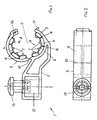
- FIG 1 shows a first embodiment of a holder.
- the holder 1 serves to receive tubular components. It has a receiving member 2.
- a vibration-damping structure 4 is formed on a wall 3 of the receiving member 2.
- the vibration-damping structure 4 limits a socket 5 which is suitable for receiving a tubular component.
- the structure 4 is substantially in the form of a honeycomb.
- the structure 4 has peripherally arranged walls 6 having supporting elements 7 penetrating into the socket 5.
- the structure 4 has mutually spaced, substantially radially extending transverse walls 8. Between two adjacent transverse walls 8 there is a respective wall 6.
- the transverse walls 8 and the walls 6 are connected to one another. As shown in the illustration in figure 1, each supporting element 7 is formed substantially centrally between two adjacent transverse walls 8.
- the supporting elements 7 are web-shaped in design and extend over the entire axial length of the transverse walls 8.
- the receiving member 2 has a shell 9 with the structure 4.
- the shell 9 is articulated on the receiving member 2 by means of a film hinge 10.
- a catch 11 is provided for locking the shell 9 to the receiving member 2.
- the catch 11 can be brought into engagement with a recess formed on the shell 9.
- the holder 1 has an orifice 12 into which a fastening element 3 can be introduced.
- the fastening element 13 can be connected, for example, to a stud which is welded on a structure, preferably a vehicle body.
- Figure 3 shows a second embodiment of a holder 1.
- the holder 1 has three holding regions for holding a tubular component.
- the outer right-hand holding region corresponds to the holder shown in figure 1 in the embodiment.
- the supporting elements 7 lie round the circumference of a common circle 14.
- the other holding regions of the holder according to figure 3 each have a wall 15 or 16 on which a respective structure 17 is formed.
- the structure 17 comprises substantially radially extending transverse walls 18.
- the transverse walls 18 are connected to one another via walls 19.
- Each wall 19 has a supporting element 7.
- the walls 19 are curved in design. In the portion 20 of the wall 19 located between a transverse wall 19 and a supporting element 7, the wall is substantially concavely curved.
- the substantially radially extending transverse walls 22, 23 which form a funnel are pressed apart. Owing to the honeycomb configuration of the structure, the structure is also peripherally elastic.
- the supporting elements 24, 25 forming the continuations of the transverse walls 22, 23 also act as blocking members, preventing a tubular component escaping from the socket 21.
Applications Claiming Priority (2)
| Application Number | Priority Date | Filing Date | Title |
|---|---|---|---|
| DE29618513U | 1996-10-23 | ||
| DE29618513U DE29618513U1 (de) | 1996-10-23 | 1996-10-23 | Halter für rohrförmige Bauteile |
Publications (3)
| Publication Number | Publication Date |
|---|---|
| EP0838626A2 true EP0838626A2 (de) | 1998-04-29 |
| EP0838626A3 EP0838626A3 (de) | 2000-01-19 |
| EP0838626B1 EP0838626B1 (de) | 2003-07-16 |
Family
ID=8031014
Family Applications (1)
| Application Number | Title | Priority Date | Filing Date |
|---|---|---|---|
| EP97308202A Expired - Lifetime EP0838626B1 (de) | 1996-10-23 | 1997-10-16 | Halter für rohrförmige Komponenten |
Country Status (3)
| Country | Link |
|---|---|
| EP (1) | EP0838626B1 (de) |
| DE (2) | DE29618513U1 (de) |
| ES (1) | ES2202559T3 (de) |
Cited By (9)
| Publication number | Priority date | Publication date | Assignee | Title |
|---|---|---|---|---|
| EP1320172A1 (de) * | 2001-12-17 | 2003-06-18 | Valeo Climatisation | Ring zur Halterung und Entkoppelung eines Elektromotors in seinem Halter und Zusammenbauverfahren |
| DE10306905A1 (de) * | 2003-02-18 | 2004-08-26 | Itw Automotive Products Gmbh & Co. Kg | Halteelement |
| EP1457684A1 (de) * | 2003-03-14 | 2004-09-15 | Faurecia Industries | Kühleranlage mit radialem Spannungsring für den Ventilatormotor, Kühlermodule für ein Frontteil, und derartiges Kraftfahrzeug |
| US7267307B2 (en) | 2003-02-18 | 2007-09-11 | Itw Automotive Products Gmbh & Co. Kg | Retaining member |
| FR2916861A1 (fr) * | 2007-06-04 | 2008-12-05 | Free Soc Par Actions Simplifie | Support pour cable a fibre optique. |
| CN103249980A (zh) * | 2010-10-15 | 2013-08-14 | 株式会社利富高 | 夹具 |
| CN108302255A (zh) * | 2018-01-30 | 2018-07-20 | 安徽江淮汽车集团股份有限公司 | 一种空调制冷管路固定卡扣 |
| DE102017102331A1 (de) | 2017-02-07 | 2018-08-09 | A. Raymond Et Cie Scs | Halteelement für eine Leitung |
| EP3534032A1 (de) | 2018-03-01 | 2019-09-04 | Newfrey LLC | Clip zur befestigung eines rohrförmigen bauteils an einem werkstück |
Families Citing this family (7)
| Publication number | Priority date | Publication date | Assignee | Title |
|---|---|---|---|---|
| DE202005008570U1 (de) | 2005-06-01 | 2005-09-08 | Trw Automotive Electronics & Components Gmbh & Co. Kg | Befestigungsvorrichtung für eine Leitung |
| DE102006026250A1 (de) * | 2006-06-06 | 2007-12-13 | BSH Bosch und Siemens Hausgeräte GmbH | Klammerelement zum Halten zumindest eines Gegenstands, insbesondere eines Kabels |
| KR20100009667A (ko) * | 2008-07-21 | 2010-01-29 | 일리노이즈 툴 워크스 인코포레이티드 | 튜브클립 |
| CN103574174A (zh) * | 2012-08-03 | 2014-02-12 | 上海电气风能有限公司 | 电缆保护零件 |
| DE102012216236A1 (de) | 2012-09-13 | 2014-03-13 | Robert Bosch Gmbh | Halter zur Befestigung eines rohrförmigen Bauteils an einer Anbaustruktur |
| DE202017101483U1 (de) * | 2017-03-14 | 2017-03-31 | Igus Gmbh | Zugentlastung und Endbefestigungsteil mit Zugentlastung |
| EP3925833B1 (de) * | 2020-06-19 | 2024-02-14 | Illinois Tool Works INC. | Befestigungsclip |
Citations (6)
| Publication number | Priority date | Publication date | Assignee | Title |
|---|---|---|---|---|
| US3606218A (en) * | 1969-03-21 | 1971-09-20 | Gen Dynamics Corp | Sound and vibration isolation support |
| EP0159958A1 (de) * | 1984-03-28 | 1985-10-30 | Hubert Combé | Rohrschellenisoliereinlage |
| FR2640349A1 (fr) * | 1988-12-09 | 1990-06-15 | Hb Tech Sa | Collier de fixation de tuyauteries |
| FR2643119A1 (fr) * | 1989-02-10 | 1990-08-17 | Renault | Dispositif de fixation d'un element tubulaire sur une paroi |
| DE3907067A1 (de) * | 1989-03-04 | 1990-09-13 | Karl Dipl Ing Sebert | Rohrhalterung |
| DE29515357U1 (de) * | 1995-09-26 | 1995-12-21 | Gerlach Zubehoertechnik Gmbh | Ein- oder zweiteilige Elastomer-Einlage für eine Rohrschelle, insbesondere eine Gleitrohrschelle |
-
1996
- 1996-10-23 DE DE29618513U patent/DE29618513U1/de not_active Expired - Lifetime
-
1997
- 1997-10-16 DE DE69723527T patent/DE69723527T2/de not_active Expired - Lifetime
- 1997-10-16 EP EP97308202A patent/EP0838626B1/de not_active Expired - Lifetime
- 1997-10-16 ES ES97308202T patent/ES2202559T3/es not_active Expired - Lifetime
Patent Citations (6)
| Publication number | Priority date | Publication date | Assignee | Title |
|---|---|---|---|---|
| US3606218A (en) * | 1969-03-21 | 1971-09-20 | Gen Dynamics Corp | Sound and vibration isolation support |
| EP0159958A1 (de) * | 1984-03-28 | 1985-10-30 | Hubert Combé | Rohrschellenisoliereinlage |
| FR2640349A1 (fr) * | 1988-12-09 | 1990-06-15 | Hb Tech Sa | Collier de fixation de tuyauteries |
| FR2643119A1 (fr) * | 1989-02-10 | 1990-08-17 | Renault | Dispositif de fixation d'un element tubulaire sur une paroi |
| DE3907067A1 (de) * | 1989-03-04 | 1990-09-13 | Karl Dipl Ing Sebert | Rohrhalterung |
| DE29515357U1 (de) * | 1995-09-26 | 1995-12-21 | Gerlach Zubehoertechnik Gmbh | Ein- oder zweiteilige Elastomer-Einlage für eine Rohrschelle, insbesondere eine Gleitrohrschelle |
Cited By (20)
| Publication number | Priority date | Publication date | Assignee | Title |
|---|---|---|---|---|
| FR2833775A1 (fr) * | 2001-12-17 | 2003-06-20 | Valeo Climatisation | Bague de maintien et de decouplage du moteur electrique dans son support et procede d'assemblage |
| EP1320172A1 (de) * | 2001-12-17 | 2003-06-18 | Valeo Climatisation | Ring zur Halterung und Entkoppelung eines Elektromotors in seinem Halter und Zusammenbauverfahren |
| US7658350B2 (en) | 2003-02-18 | 2010-02-09 | Itw Automotive Products Gmbh & Co Kg | Retaining member |
| DE10306905A1 (de) * | 2003-02-18 | 2004-08-26 | Itw Automotive Products Gmbh & Co. Kg | Halteelement |
| DE10306905C5 (de) * | 2003-02-18 | 2012-05-24 | Itw Automotive Products Gmbh & Co. Kg | Halteelement |
| DE10306905B4 (de) * | 2003-02-18 | 2005-01-27 | Itw Automotive Products Gmbh & Co. Kg | Halteelement |
| US7267307B2 (en) | 2003-02-18 | 2007-09-11 | Itw Automotive Products Gmbh & Co. Kg | Retaining member |
| US7771177B2 (en) | 2003-03-14 | 2010-08-10 | Faurecia Cooling Systems | Ventilation assembly having a collar for the radial clamping of the fan motor, corresponding cooling module for the front unit, and corresponding motor vehicle |
| FR2852283A1 (fr) * | 2003-03-14 | 2004-09-17 | Faurecia Ind | Ensemble de ventilation a collier de serrage radial du moteur de ventilateur, module de refroidissement de bloc avant et vehicule automobile correspondants |
| EP1457684A1 (de) * | 2003-03-14 | 2004-09-15 | Faurecia Industries | Kühleranlage mit radialem Spannungsring für den Ventilatormotor, Kühlermodule für ein Frontteil, und derartiges Kraftfahrzeug |
| WO2008152329A1 (fr) | 2007-06-04 | 2008-12-18 | Free | Support pour cable a fibre optique |
| FR2916861A1 (fr) * | 2007-06-04 | 2008-12-05 | Free Soc Par Actions Simplifie | Support pour cable a fibre optique. |
| CN103249980A (zh) * | 2010-10-15 | 2013-08-14 | 株式会社利富高 | 夹具 |
| US9181966B2 (en) | 2010-10-15 | 2015-11-10 | Nifco Inc. | Clamp |
| CN103249980B (zh) * | 2010-10-15 | 2015-11-25 | 株式会社利富高 | 夹具 |
| DE102017102331A1 (de) | 2017-02-07 | 2018-08-09 | A. Raymond Et Cie Scs | Halteelement für eine Leitung |
| WO2018145889A1 (en) | 2017-02-07 | 2018-08-16 | A. Raymond Et Cie Scs | Holding element for a duct |
| DE102017102331B4 (de) * | 2017-02-07 | 2020-08-13 | A. Raymond Et Cie Scs | Halteelement für eine Leitung |
| CN108302255A (zh) * | 2018-01-30 | 2018-07-20 | 安徽江淮汽车集团股份有限公司 | 一种空调制冷管路固定卡扣 |
| EP3534032A1 (de) | 2018-03-01 | 2019-09-04 | Newfrey LLC | Clip zur befestigung eines rohrförmigen bauteils an einem werkstück |
Also Published As
| Publication number | Publication date |
|---|---|
| EP0838626A3 (de) | 2000-01-19 |
| ES2202559T3 (es) | 2004-04-01 |
| DE69723527D1 (de) | 2003-08-21 |
| DE29618513U1 (de) | 1996-12-12 |
| DE69723527T2 (de) | 2004-06-03 |
| EP0838626B1 (de) | 2003-07-16 |
Similar Documents
| Publication | Publication Date | Title |
|---|---|---|
| EP0838626A2 (de) | Halter für rohrförmige Komponenten | |
| US5257768A (en) | Vibration-damping holding element for pipelines | |
| US8827214B2 (en) | Clamp | |
| US5947426A (en) | Plastic holding element with flexible connection between attachment and holding member | |
| KR100382978B1 (ko) | 볼유지부를구비한볼죠인트 | |
| EP1469249B1 (de) | Schwingungsisolierende Rohrschelle für langgestreckte Gegenstände | |
| JP4751006B2 (ja) | 車両ブレーキ系の液圧式ユニットを車両に弾性的に支承するための装置 | |
| ES2273101T5 (es) | Medio de retención | |
| EP1529997B1 (de) | Isolierender Leitungshalter aus mehreren Materialien | |
| EP2131084B1 (de) | Befestigungselement zum Befestigen ein Strukturelement an einem Bolzen | |
| US5170984A (en) | Holding element made of plastic | |
| US20120153095A1 (en) | Conductive floating pipe assembly clip | |
| EP1209398A2 (de) | Schnappanordnung zur lösbaren Befestigung eines Gegenstandes an mindestens einer Leitung | |
| US20050253025A1 (en) | Holding clip | |
| WO1998034045A1 (en) | Body mount assembly | |
| WO1996024511A3 (de) | Anordnung zur befestigung eines aus einem gehäuseboden und einem gehäusedeckel bestehenden airbag-gehäuse im lenkrad | |
| JP3946293B2 (ja) | 継手の支承シェルを取付け穴内に固定する用具 | |
| US4531786A (en) | Wheel cover for wheels of a passenger motor vehicle | |
| JPH09184580A (ja) | 少なくとも1本の管状部品を支持体に固定する保持部材 | |
| EP1260408A3 (de) | Zusatzgriffbefestigung für ein modulare Fahrzeugdachverkleidung | |
| EP0926419A3 (de) | Schlauchschelle | |
| ES2271853T3 (es) | Junta articulada. | |
| US4470639A (en) | Wheel cover for a passenger motor vehicle | |
| US4512614A (en) | Wheel cover with retainment system | |
| CA2231311C (en) | Integrated system for protecting and fastening pipes to a supporting structure, particularly of a vehicle |
Legal Events
| Date | Code | Title | Description |
|---|---|---|---|
| PUAI | Public reference made under article 153(3) epc to a published international application that has entered the european phase |
Free format text: ORIGINAL CODE: 0009012 |
|
| AK | Designated contracting states |
Kind code of ref document: A2 Designated state(s): AT BE CH DE DK LI |
|
| AX | Request for extension of the european patent |
Free format text: AL;LT;LV;RO;SI |
|
| PUAL | Search report despatched |
Free format text: ORIGINAL CODE: 0009013 |
|
| AK | Designated contracting states |
Kind code of ref document: A3 Designated state(s): AT BE CH DE DK ES FI FR GB GR IE IT LI LU MC NL PT SE |
|
| AX | Request for extension of the european patent |
Free format text: AL;LT;LV;RO;SI |
|
| RIC1 | Information provided on ipc code assigned before grant |
Free format text: 7F 16L 55/033 A, 7F 16L 3/10 B, 7F 16L 3/12 B, 7F 16L 3/223 B |
|
| AKX | Designation fees paid | ||
| RBV | Designated contracting states (corrected) |
Designated state(s): AT BE CH DE DK LI |
|
| 17P | Request for examination filed |
Effective date: 20000818 |
|
| RBV | Designated contracting states (corrected) |
Designated state(s): DE ES FR GB IT |
|
| REG | Reference to a national code |
Ref country code: DE Ref legal event code: 8566 |
|
| 17Q | First examination report despatched |
Effective date: 20020416 |
|
| RAP1 | Party data changed (applicant data changed or rights of an application transferred) |
Owner name: EMHART LLC |
|
| GRAH | Despatch of communication of intention to grant a patent |
Free format text: ORIGINAL CODE: EPIDOS IGRA |
|
| RAP1 | Party data changed (applicant data changed or rights of an application transferred) |
Owner name: NEWFREY LLC |
|
| GRAH | Despatch of communication of intention to grant a patent |
Free format text: ORIGINAL CODE: EPIDOS IGRA |
|
| GRAA | (expected) grant |
Free format text: ORIGINAL CODE: 0009210 |
|
| AK | Designated contracting states |
Designated state(s): DE ES FR GB IT |
|
| REG | Reference to a national code |
Ref country code: GB Ref legal event code: FG4D |
|
| REF | Corresponds to: |
Ref document number: 69723527 Country of ref document: DE Date of ref document: 20030821 Kind code of ref document: P |
|
| RAP2 | Party data changed (patent owner data changed or rights of a patent transferred) |
Owner name: NEWFREY LLC |
|
| REG | Reference to a national code |
Ref country code: ES Ref legal event code: FG2A Ref document number: 2202559 Country of ref document: ES Kind code of ref document: T3 |
|
| ET | Fr: translation filed | ||
| PLBE | No opposition filed within time limit |
Free format text: ORIGINAL CODE: 0009261 |
|
| STAA | Information on the status of an ep patent application or granted ep patent |
Free format text: STATUS: NO OPPOSITION FILED WITHIN TIME LIMIT |
|
| 26N | No opposition filed |
Effective date: 20040419 |
|
| PGFP | Annual fee paid to national office [announced via postgrant information from national office to epo] |
Ref country code: IT Payment date: 20131025 Year of fee payment: 17 Ref country code: ES Payment date: 20131028 Year of fee payment: 17 |
|
| PGFP | Annual fee paid to national office [announced via postgrant information from national office to epo] |
Ref country code: GB Payment date: 20141027 Year of fee payment: 18 Ref country code: DE Payment date: 20141029 Year of fee payment: 18 Ref country code: FR Payment date: 20141017 Year of fee payment: 18 |
|
| PG25 | Lapsed in a contracting state [announced via postgrant information from national office to epo] |
Ref country code: IT Free format text: LAPSE BECAUSE OF NON-PAYMENT OF DUE FEES Effective date: 20141016 |
|
| REG | Reference to a national code |
Ref country code: ES Ref legal event code: FD2A Effective date: 20151127 |
|
| PG25 | Lapsed in a contracting state [announced via postgrant information from national office to epo] |
Ref country code: ES Free format text: LAPSE BECAUSE OF NON-PAYMENT OF DUE FEES Effective date: 20141017 |
|
| REG | Reference to a national code |
Ref country code: DE Ref legal event code: R119 Ref document number: 69723527 Country of ref document: DE |
|
| GBPC | Gb: european patent ceased through non-payment of renewal fee |
Effective date: 20151016 |
|
| PG25 | Lapsed in a contracting state [announced via postgrant information from national office to epo] |
Ref country code: GB Free format text: LAPSE BECAUSE OF NON-PAYMENT OF DUE FEES Effective date: 20151016 Ref country code: DE Free format text: LAPSE BECAUSE OF NON-PAYMENT OF DUE FEES Effective date: 20160503 |
|
| REG | Reference to a national code |
Ref country code: FR Ref legal event code: ST Effective date: 20160630 |
|
| PG25 | Lapsed in a contracting state [announced via postgrant information from national office to epo] |
Ref country code: FR Free format text: LAPSE BECAUSE OF NON-PAYMENT OF DUE FEES Effective date: 20151102 |