EP0837812B2 - Stress compensation device for the cable-type control of a derailleur, particularly for a bicycle - Google Patents
Stress compensation device for the cable-type control of a derailleur, particularly for a bicycle Download PDFInfo
- Publication number
- EP0837812B2 EP0837812B2 EP96927721A EP96927721A EP0837812B2 EP 0837812 B2 EP0837812 B2 EP 0837812B2 EP 96927721 A EP96927721 A EP 96927721A EP 96927721 A EP96927721 A EP 96927721A EP 0837812 B2 EP0837812 B2 EP 0837812B2
- Authority
- EP
- European Patent Office
- Prior art keywords
- derailleur
- cable
- spring
- compensation
- secured
- Prior art date
- Legal status (The legal status is an assumption and is not a legal conclusion. Google has not performed a legal analysis and makes no representation as to the accuracy of the status listed.)
- Expired - Lifetime
Links
Images


Classifications
-
- B—PERFORMING OPERATIONS; TRANSPORTING
- B62—LAND VEHICLES FOR TRAVELLING OTHERWISE THAN ON RAILS
- B62M—RIDER PROPULSION OF WHEELED VEHICLES OR SLEDGES; POWERED PROPULSION OF SLEDGES OR SINGLE-TRACK CYCLES; TRANSMISSIONS SPECIALLY ADAPTED FOR SUCH VEHICLES
- B62M25/00—Actuators for gearing speed-change mechanisms specially adapted for cycles
- B62M25/02—Actuators for gearing speed-change mechanisms specially adapted for cycles with mechanical transmitting systems, e.g. cables, levers
-
- Y—GENERAL TAGGING OF NEW TECHNOLOGICAL DEVELOPMENTS; GENERAL TAGGING OF CROSS-SECTIONAL TECHNOLOGIES SPANNING OVER SEVERAL SECTIONS OF THE IPC; TECHNICAL SUBJECTS COVERED BY FORMER USPC CROSS-REFERENCE ART COLLECTIONS [XRACs] AND DIGESTS
- Y10—TECHNICAL SUBJECTS COVERED BY FORMER USPC
- Y10T—TECHNICAL SUBJECTS COVERED BY FORMER US CLASSIFICATION
- Y10T74/00—Machine element or mechanism
- Y10T74/20—Control lever and linkage systems
- Y10T74/20396—Hand operated
- Y10T74/20402—Flexible transmitter [e.g., Bowden cable]
Definitions
- the present invention relates to a device 1 for force compensation in a cable control with two derailleurs, in particular for a bicycle.
- the movable element is a deformable parallelogram which deviates from the hub carrying the gears under the spring return effect and which is approaching under the action traction of the cable when the user exerts a force on the control means.
- tray In the case of trays, it is different
- the smaller tray is on the side of the frame and the guide element also in the form of a deformable parallelogram is returned to the frame and the operating member is actuated by the user for move from the smallest to the largest plateau.
- the difference in diameter is much greater and the effort required is much greater.
- Such an arrangement passes the forces of compensation efforts and reactions, through a pulley and an axis and not directly on the parts to be relieved such as miniaturized parts
- the invention provides a force compensation device according to claim 1.
- the compensation spring is a small diameter spring, with a large number of turns and with a relatively low stiffness, which presents with contiguous turns in the compressed state, the effort to compress it or the returned force being substantially equal to the effort to compress or the force returned by the return spring of the derailleur.
- the device according to the invention comprises two independent springs, each acting on the corresponding cable, so as to obtain an effort compensation in all circumstances.
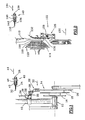
- FIG. 1 there is shown a portion of the frame 10 of a bicycle, in which is mounted a crankset 12 which drives trays 14, there being three in the example shown.
- These trays comprise a small plate 16, an intermediate plate 18 and a large plate 20, arranged so that the small plate is inside, that is to say close to the frame and the large outer plate, ie away from the frame .
- This arrangement is generally adopted because it is dictated by the combination with the gears whose arrangement is reversed as will be explained later, to ensure that the chain is well aligned during the greatest efforts, that is to say for the smaller development small plateau / large pinion, and for the largest development, large plateau / small pinion.
- a plate derailleur 22 comprising a movable arm 24, consisting of a deformable parallelogram 26, with a return spring 28 in the direction of the arrow 30, that is to say from the outside towards inside and a control cable 32 sliding in known manner in a sheath 34, one of the ends 36 of this cable is connected to the movable arm.
- control means shown very schematically at 40 in the form of a stop 42 of the sheath 34 and in the form of an arrow 44, representative of the displacement generated in the two senses, by a rotating handle.
- a spring is more particularly chosen with a large number of turns and a low stiffness so that the effort required for its compression is progressive and low while the resulting return force is substantially equivalent to that of the return spring 28 of the front derailleur 22.
- This return spring is preferably contiguous turns in the fully compressed state.
- the return spring 28 is shown as a compression spring, which facilitates understanding.
- the user can then continue the development changes by pulling cable to the position shown on the figure 3C .
- the assistance device makes it possible to let the return spring of each of the derailleurs act as it should and, on the other hand, facilitates the movements by distributing the forces, that is to say that it stores energy. and return it when it is needed to assist the user.
- This distribution is of particular interest because the two front and rear derailleur controls are twinned or more precisely controlled by the same handle with means for generating a differential movement between the two cables of the deraille.
- the compensation may allow a gentle control of the assembly, while the efforts to be exerted on the common control member may be important to the point of leading to a somewhat hard maneuver.
Abstract
Description
La présente invention a pour objet un Dispositif 1 de compensation d'effort dans une commande à câble à deux dérailleurs, notamment pour un vélo.The present invention relates to a device 1 for force compensation in a cable control with two derailleurs, in particular for a bicycle.
On connaît des ensembles de changement de vitesses du type comprenant :
- un moyen de commande tel qu'une manette, un levier ou encore une poignée tournante, fixée sur le cadre et à proximité du guidon, manoeuvrable par l'utilisateur,
- un câble de commande, et
- un dérailleur composé d'une platine fixée sur le cadre, d'un élément mobile de guidage de la chaîne, généralement du type parallélogramme, déplaçable latéralement et d'un ressort de rappel de cet élément mobile de guidage dans l'une des positions extrêmes.
- control means such as a joystick, a lever or a rotating handle, fixed on the frame and near the handlebar, which can be operated by the user,
- a control cable, and
- a derailleur composed of a plate fixed to the frame, a movable chain guide element, generally of the parallelogram type, laterally displaceable and a return spring of this movable guide element in one of the extreme positions .
Dans le cas d'un dérailleur arrière qui assure le changement de pignons, l'élément mobile est un parallélogramme déformable qui s'écarte du moyeu portant les pignons sous l'effet de rappel du ressort et qui s'en rapproche sous l'action de traction du câble lorsque l'utilisateur exerce un effort sur le moyen de commande.In the case of a rear derailleur which ensures the change of gears, the movable element is a deformable parallelogram which deviates from the hub carrying the gears under the spring return effect and which is approaching under the action traction of the cable when the user exerts a force on the control means.
On peut remarquer que dans le cas des pignons, le saut d'un pignon à l'autre pour la remontée du plus petit vers le plus grand reste d'une amplitude relativement faible car les pignons sont bien étagés, si bien que même difficile, l'effort reste encore raisonnable, bien qu'il faille bander le ressort de rappel pour qu'en retour il puisse libérer l'énergie emmagasinée.We can notice that in the case of gables, the jump from one pinion to the other for the ascent from the smallest to the largest remains of a relatively small amplitude because the gables are well staggered, so that even difficult, the effort is still reasonable, although it is necessary to bend the return spring so that in return it can release the energy stored.
Dans le cas des plateaux, il en est autrement Le plateau le plus petit est du côté du cadre et l'élément de guidage également sous forme de parallélogramme déformable est rappelé vers le cadre et l'organe de manoeuvre est actionné par l'utilisateur pour passer du plus petit au plus grand plateau. La différence de diamètre est là beaucoup plus importante et l'effort à fournir est beaucoup plus grand.In the case of trays, it is different The smaller tray is on the side of the frame and the guide element also in the form of a deformable parallelogram is returned to the frame and the operating member is actuated by the user for move from the smallest to the largest plateau. The difference in diameter is much greater and the effort required is much greater.
Qui plus est, on constate que lorsque l'utilisateur veut passer du plus grand plateau à un plateau inférieur, il faut tout d'abord faire monter la chaîne au delà du diamètre du grand plateau considéré au sommet des dents et non plus au fond de gorge, ce qui requiert un effort supplémentaire alors que, justement, on cherche à diminuer l'effort à fournir. Ceci conduit à prévoir un ressort de forte capacité élastique pour pouvoir vaincre ce point dur.What is more, we see that when the user wants to go from the largest plateau to a lower plateau, it is first necessary to raise the chain beyond the diameter of the large plateau considered at the top of the teeth and no longer at the bottom of throat, which requires additional effort when, precisely, we try to reduce the effort to provide. This leads to provide a spring of high elastic capacity to be able to overcome this hard point.
Dans le sens de la montée d'un plateau inférieur vers un plateau supérieur, l'utilisateur est obligé de vaincre d'un part ce point dur et d'autre part il lui faut comprimer le ressort, ce qui conduit à des efforts importants à exercer sur la manette, le levier ou la poignée tournante, ceci au détriment de la précision du geste, de l'attention en promenade ou de la concentration en compétition. On s'est même aperçu que cela devient rédhibitoire pour les enfants ou certaines personnes d'une force physique moyenne. Dans tous les cas, il est certain que l'utilisateur a tendance à ajouter un mouvement du corps pour compenser, ce qui le déséquilibre plus ou moins et lorsque l'on sait qu'un tel geste de manoeuvre des dérailleurs s'effectue plusieurs dizaines de fois, voire plusieurs centaines de fois au cours d'une sortie, on comprend l'intérêt qu'il pourrait y avoir à maîtriser l'effort de manoeuvre nécessaire.In the direction of the rise of a lower plate towards an upper plate, the user is obliged to overcome on the one hand this hard point and on the other hand it is necessary for him to compress the spring, which leads to important efforts to exercise on the lever, the lever or the revolving handle, this to the detriment of the precision of the gesture, the attention in walk or the concentration in competition. It has even been seen that it becomes prohibitive for children or certain people of average physical strength. In all cases, it is certain that the user has a tendency to add a movement of the body to compensate, which more or less unbalances it and when it is known that such a gesture of maneuvering the derailleurs takes several tens many times, even several hundred times during an outing, one understands the interest that there could be to control the necessary maneuvering force.
On connaît le
Un tel agencement fait transiter les efforts de compensation efforts et réactions, à travers une poulie et un axe et non directement sur les pièces à soulager telles que des pièces miniaturiséesSuch an arrangement passes the forces of compensation efforts and reactions, through a pulley and an axis and not directly on the parts to be relieved such as miniaturized parts
C'est le but de l'invention de proposer un dispositif de compensation d'effort dans une commande à câble de deux dérailleurs, notamment pour un vélo, qui favorise les actions pour l'utilisateur en équilibrant les actions tant pour la montée des vitesses que pour la descente, qui est d'un surcoût négligeable, qui est adaptable sur les systèmes existants, qui est quasiment sans conséquence sur le poids, qui est d'un encombrement réduit et qui est parfaitement intégrable tant du point de vue ergonomique qu'esthétique.It is the object of the invention to provide a force compensation device in a cable control of two derailleurs, in particular for a bicycle, which favors actions for the user by balancing the actions for both the rise of the speeds for the descent, which is negligible additional cost, which is adaptable to existing systems, which is almost without weight, which is of a small footprint and which is perfectly integrable both ergonomically as well as aesthetic.
A cet effet l'invention prevoi un dispositif de compensation d'effort selon la revendication 1.For this purpose the invention provides a force compensation device according to claim 1.
Selon une autre caractéristique preferable, le ressort de compensation est un ressort de faible diamètre, avec un grand nombre de spires et avec une raideur relativement faible, qui se présente avec des spires jointives à l'état comprimé, l'effort pour le comprimer ou l'effort restitué étant sensiblement égal à l'effort pour comprimer ou à l'effort restitué par le ressort de rappel du dérailleur.According to another preferable characteristic, the compensation spring is a small diameter spring, with a large number of turns and with a relatively low stiffness, which presents with contiguous turns in the compressed state, the effort to compress it or the returned force being substantially equal to the effort to compress or the force returned by the return spring of the derailleur.
Le dispositif selon l'invention comprend deux ressorts indépendants, chacun agissant sur le câble correspondant, en sorte d'obtenir une compensation des efforts en toutes circonstances.The device according to the invention comprises two independent springs, each acting on the corresponding cable, so as to obtain an effort compensation in all circumstances.
L'invention est récrite ci-après selon un mode de réalisation particulier, non limitatif, en regard des dessins annexés sur lesquels les figures représentent :
-
figure 1 , une vue simplifiée d'un dérailleur de plateaux, -
figure 2 , une vue simplifiée d'un dérailleur de pignons, -
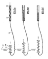
figures 3A à 3E , un synoptique des étapes de fonctionnement du dérailleur de plateaux avec le dispositif de compensation selon l'invention, et -
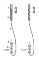
figures 4A à 4E , un synoptique des étapes de fonctionnement du dérailleur de pignons avec le dispositif de compensation selon l'invention.
-
figure 1 , a simplified view of a plate derailleur, -
figure 2 , a simplified view of a gears derailleur, -
FIGS. 3A to 3E , a block diagram of the steps of operation of the plate derailleur with the compensation device according to the invention, and -
FIGS. 4A to 4E , a block diagram of the steps of operation of the gear derailleur with the compensation device according to the invention.
Sur la
Ces plateaux comprennent un petit plateau 16, un plateau intermédiaire 18 et un grand plateau 20, disposés en sorte que le petit plateau soit intérieur, c'est à dire proche du cadre et le grand plateau extérieur, c'est à dire éloigné du cadre.These trays comprise a
Cette disposition est généralement adoptée car elle est dictée par la combinaison avec les pignons dont l'agencement est inversé comme cela sera expliqué ultérieurement, pour faire en sorte que la chaîne soit bien alignée lors des plus grands efforts, c'est à dire pour le plus petit développement petit plateau/grand pignon, et pour le plus grand développement, grand plateau/petit pignon.This arrangement is generally adopted because it is dictated by the combination with the gears whose arrangement is reversed as will be explained later, to ensure that the chain is well aligned during the greatest efforts, that is to say for the smaller development small plateau / large pinion, and for the largest development, large plateau / small pinion.
L'ensemble est complété par un dérailleur de plateaux 22, comprenant un bras mobile 24, constitué d'un parallélogramme déformable 26, avec un ressort 28 de rappel dans le sens de la flèche 30, c'est à dire de l'extérieur vers l'intérieur et d'un câble de commande 32 coulissant de façon connue dans une gaine 34, l'une des extrémités 36 de ce câble est reliée au bras mobile.The assembly is completed by a
L'autre extrémité 38 de ce câble est reliée à des moyens de commande représentés de façon très schématique en 40 sous la forme d'une butée 42 de la gaine 34 et sous la forme d'une flèche 44, représentative du déplacement généré dans les deux sens, par une poignée tournante.The
Un ressort est plus particulièrement choisi avec un nombre de spires important et une raideur faible pour que l'effort nécessaire à sa compression soit progressif et faible alors que l'effort de rappel résultant est sensiblement équivalent à celui du ressort de rappel 28 du dérailleur avant 22. Ce ressort de rappel est de préférence à spires jointives à l'état complètement comprimé.A spring is more particularly chosen with a large number of turns and a low stiffness so that the effort required for its compression is progressive and low while the resulting return force is substantially equivalent to that of the
Le fonctionnement de ces moyens de compensation est indiqué ci-après, en regard des
Lorsque l'utilisateur pédale avec un développement important et que la chaîne est donc sur le grand plateau 20,
Lorsque l'utilisateur souhaite diminue son développement, voir la
Lorsque l'utilisateur souhaite encore diminuer le développement, il descend la chaîne sur le petit plateau 16 en manoeuvrant à nouveau la poignée pour relâcher encore une longueur de câble donnée.When the user still wishes to reduce the development, he descends the chain on the
Le résultat se lit sur la
Ainsi lorsque l'utilisateur effectue le cycle inverse, voir
On remarque la symétrie d'agencement pour ce qui concerne le dérailleur arrière représenté sur la
Les éléments identiques portent les mêmes références augmentées de 100.The identical elements bear the same references increased by 100.
Le fonctionnement est identique en ce sens que lorsque la chaîne est sur le plus petit pignon 116, le ressort 128 du bras mobile 126 est détendu et le ressort de compensation 146 est comprimé. Par contre l'effet sur les développements est inversé puisque le passage du grand pignon sur le petit pignon augmente le développement contrairement aux plateaux.The operation is identical in that when the chain is on the
Lorsque l'utilisateur est au développement le plus important, c'est à dire avec le plus petit pignon, pour diminuer ce développement, il lui faut monter quelques pignons et pour cela il exerce une traction sur le câble pour comprimer le ressort de rappel 128 et simultanément l'énergie emmagasinée par le ressort de compensation 146 assiste l'utilisateur par une détente partielle dudit ressort. Ceci est représenté sur la
L'utilisateur peut ensuite poursuivre les modifications de développement en exerçant des tractions supplémentaires sur le câble jusqu'à la position représentée sur la
Les
Ainsi le dispositif d'assistance selon l'invention permet de laisser le ressort de rappel de chacun des dérailleurs agir comme il se doit et facilite par contre les mouvements en répartissant les efforts, c'est à dire qu'il emmagasine de l'énergie et la restitue au moment où elle est nécessaire pour assister l'utilisateur.
Cette répartition trouve un intérêt tout particulier parce que les deux commandes des dérailleurs avant et arrière sont jumelées ou plus exactement commandées par une même poignée avec des moyens pour générer un déplacement différentiel entre les deux câbles des dérailleurs. En effet, dans ce cas, la compensation peut permettre une commande douce de l'ensemble, alors que les efforts à exercer sur l'organe de commande commun pourraient s'avérer importants au point de conduire à une manoeuvre quelque peu dure.Thus, the assistance device according to the invention makes it possible to let the return spring of each of the derailleurs act as it should and, on the other hand, facilitates the movements by distributing the forces, that is to say that it stores energy. and return it when it is needed to assist the user.
This distribution is of particular interest because the two front and rear derailleur controls are twinned or more precisely controlled by the same handle with means for generating a differential movement between the two cables of the derailleurs. Indeed, in this case, the compensation may allow a gentle control of the assembly, while the efforts to be exerted on the common control member may be important to the point of leading to a somewhat hard maneuver.
On remarque également que dans le moyen de commande, il faut que le câble soit solidaire de l'organe d'actionnement pour obtenir un effet poussé ou tiré car le ressort de rappel du dérailleur n'assure pas une fraction forte du câble.Note also that in the control means, it is necessary that the cable is secured to the actuating member to obtain a pushed or pulled effect because the return spring of the derailleur does not ensure a strong fraction of the cable.
Claims (3)
- Force compensation device in a cable control for two derailleurs (22, 122) for a chain, notably fixed to the frame (10, 110) of a bicycle with several chainwheels (16, 18, 20) and cogs (116, 118, 120), respectively, including two cables (32, 132) each comprising a first end (36, 136) fixed to its respective derailleur and a second end (38, 138) secured to a means of a monocontrol manoeuvring rotary grip generating a translation movement (44, 144),each cable sliding in a sheath (34, 134) coming into abutment at a stop (42, 142),
wherein the means of the manoeuvring rotary grip is equipped with means for generating a differential movement between the two cables (44, 46) of the derailleurs (22, 122), and
wherein each derailleur is equipped with a spring (28, 128) being in the compressed state respectively when the chain is on the largest chainwheel or cog, respectively,
wherein said device comprises two independent compensation springs (46,146),each acting as opposing-effect elastic restoring elements and being in the extended state when the return spring of the corresponding derailleur is in the compressed state and in the compressed state when the return spring of the derailleur is in the extended state,
wherein each compensation spring (46, 146) is disposed between a fixed stop secured to the bicycle and a fixed stop secured to the second end (38, 138) of the respective cable (32, 132). - Device according to Claim 1, characterised in that each compensation spring (46, 146) is disposed coaxially with its respective cable (32, 132) and is interposed between a fixed stop (42, 142) secured to the frame (10,110) and the second end (38, 138) of this cable.
- Device according to Claim 2, characterised in that each compensation spring (46, 146) is a small-diameter spring, with a large number of turns and with a relatively low stiffness, which has contiguous turns in the compressed state, the force for compressing it or the restored force being substantially equal to the force for compressing or the force restored by the return spring of the derailleur.
Priority Applications (1)
| Application Number | Priority Date | Filing Date | Title |
|---|---|---|---|
| EP96927721A EP0837812B2 (en) | 1995-08-03 | 1996-08-01 | Stress compensation device for the cable-type control of a derailleur, particularly for a bicycle |
Applications Claiming Priority (6)
| Application Number | Priority Date | Filing Date | Title |
|---|---|---|---|
| EP95450012A EP0727348B2 (en) | 1995-02-15 | 1995-08-03 | Method of determining the transmission ratios for a bicycle chain shifter and shift device for implementing the ratios thus determined |
| EP95450012 | 1995-08-03 | ||
| FR9511579 | 1995-09-27 | ||
| FR9511579A FR2737463B1 (en) | 1995-08-03 | 1995-09-27 | STRESS COMPENSATION DEVICE FOR A WIRE DERAILLEUR DRIVE, PARTICULARLY FOR A BIKE |
| PCT/FR1996/001222 WO1997006048A1 (en) | 1995-08-03 | 1996-08-01 | Stress compensation device for the cable-type control of a derailleur, particularly for a bicycle |
| EP96927721A EP0837812B2 (en) | 1995-08-03 | 1996-08-01 | Stress compensation device for the cable-type control of a derailleur, particularly for a bicycle |
Publications (3)
| Publication Number | Publication Date |
|---|---|
| EP0837812A1 EP0837812A1 (en) | 1998-04-29 |
| EP0837812B1 EP0837812B1 (en) | 1999-11-17 |
| EP0837812B2 true EP0837812B2 (en) | 2009-03-25 |
Family
ID=26140618
Family Applications (1)
| Application Number | Title | Priority Date | Filing Date |
|---|---|---|---|
| EP96927721A Expired - Lifetime EP0837812B2 (en) | 1995-08-03 | 1996-08-01 | Stress compensation device for the cable-type control of a derailleur, particularly for a bicycle |
Country Status (10)
| Country | Link |
|---|---|
| US (1) | US6517456B1 (en) |
| EP (1) | EP0837812B2 (en) |
| JP (1) | JPH11510128A (en) |
| CN (1) | CN1077532C (en) |
| AT (1) | ATE186693T1 (en) |
| AU (1) | AU6743796A (en) |
| CA (1) | CA2253892A1 (en) |
| DE (1) | DE69605197T2 (en) |
| ES (1) | ES2142082T3 (en) |
| WO (1) | WO1997006048A1 (en) |
Families Citing this family (3)
| Publication number | Priority date | Publication date | Assignee | Title |
|---|---|---|---|---|
| US7007569B1 (en) * | 2003-03-03 | 2006-03-07 | The United States Of America As Represented By The Secretary Of The Navy | Telescoping and locking lever arm |
| NO326574B1 (en) * | 2007-03-13 | 2009-01-12 | Sapdesign As | Device by chair with adjustable angle between chair seat and back |
| TWI647146B (en) * | 2017-11-10 | 2019-01-11 | 台灣微轉股份有限公司 | Bicycle rear derailleur |
Citations (3)
| Publication number | Priority date | Publication date | Assignee | Title |
|---|---|---|---|---|
| DE689783C (en) † | 1938-01-11 | 1940-04-02 | Hans Ado Brandt | Wire drawing system |
| US4194408A (en) † | 1976-10-30 | 1980-03-25 | Eberhard Hedrich | Gear-shift control for bicycle transmission |
| WO1995003208A1 (en) † | 1993-07-23 | 1995-02-02 | Heinrich Elsen | Bicycle gearchange |
Family Cites Families (16)
| Publication number | Priority date | Publication date | Assignee | Title |
|---|---|---|---|---|
| FR796583A (en) | 1935-10-22 | 1936-04-10 | Spiral gear change derailleur adaptable to bicycles | |
| DE1605783A1 (en) * | 1966-12-23 | 1971-01-21 | Juy Lucien Charles Hippolyte | Actuating device, especially for speed change transmissions of bicycles, bicycles with auxiliary engine and motorcycles |
| US3535950A (en) * | 1967-11-13 | 1970-10-27 | Shimano Industrial Co | Exposed speed change mechanism for a bicycle |
| JPS5554628Y2 (en) * | 1977-02-14 | 1980-12-17 | ||
| US4267742A (en) * | 1978-11-22 | 1981-05-19 | Cabeza Maximino R | Single lever control mechanism for bicycle front and rear derailleurs |
| DE3200562A1 (en) * | 1982-01-12 | 1983-07-21 | Stephan 8700 Würzburg Lutze | Indexing means for the individual gears with respect to the front derailleur for bicycles |
| US4507101A (en) | 1982-04-07 | 1985-03-26 | Shimano Industrial Company Limited | Speed control device for a bicycle |
| DE3400432A1 (en) * | 1984-01-09 | 1985-07-18 | Fichtel & Sachs Ag, 8720 Schweinfurt | Derailleur device |
| US5134897A (en) * | 1989-10-20 | 1992-08-04 | Campagnolo S.R.L. | Twist-grip device for operating the gears of a bicycle |
| US5135441A (en) * | 1991-05-24 | 1992-08-04 | Mark Gelbien | Shifting apparatus for multispeed bicycles |
| JP2965878B2 (en) | 1994-11-25 | 1999-10-18 | 株式会社シマノ | Chain guide positioning mechanism for bicycle front transmission |
| DE69515826T2 (en) | 1994-12-20 | 2000-11-02 | Shimano Kk | Control device for a bicycle gear shift with a spring device |
| AU4383796A (en) | 1994-12-22 | 1996-07-10 | Jochen Wendler | Gear-changing mechanism for a bicycle |
| WO1996032316A1 (en) * | 1995-04-11 | 1996-10-17 | Garcia Prada Jose Manuel | Integrated device for the switching of developments in bicycles |
| DE19534438C1 (en) | 1995-09-16 | 1996-09-19 | Daimler Benz Ag | Automatic play compensation for handbrakes esp. of motor cars |
| US5613405A (en) | 1995-11-13 | 1997-03-25 | Teleflex Incorporated | Cable assembly with telescoping core terminal |
-
1996
- 1996-08-01 AT AT96927721T patent/ATE186693T1/en not_active IP Right Cessation
- 1996-08-01 CA CA002253892A patent/CA2253892A1/en not_active Abandoned
- 1996-08-01 CN CN96197011A patent/CN1077532C/en not_active Expired - Fee Related
- 1996-08-01 EP EP96927721A patent/EP0837812B2/en not_active Expired - Lifetime
- 1996-08-01 AU AU67437/96A patent/AU6743796A/en not_active Abandoned
- 1996-08-01 WO PCT/FR1996/001222 patent/WO1997006048A1/en active IP Right Grant
- 1996-08-01 ES ES96927721T patent/ES2142082T3/en not_active Expired - Lifetime
- 1996-08-01 JP JP9508166A patent/JPH11510128A/en active Pending
- 1996-08-01 DE DE69605197T patent/DE69605197T2/en not_active Expired - Fee Related
-
2000
- 2000-09-14 US US09/662,334 patent/US6517456B1/en not_active Expired - Fee Related
Patent Citations (3)
| Publication number | Priority date | Publication date | Assignee | Title |
|---|---|---|---|---|
| DE689783C (en) † | 1938-01-11 | 1940-04-02 | Hans Ado Brandt | Wire drawing system |
| US4194408A (en) † | 1976-10-30 | 1980-03-25 | Eberhard Hedrich | Gear-shift control for bicycle transmission |
| WO1995003208A1 (en) † | 1993-07-23 | 1995-02-02 | Heinrich Elsen | Bicycle gearchange |
Also Published As
| Publication number | Publication date |
|---|---|
| EP0837812A1 (en) | 1998-04-29 |
| EP0837812B1 (en) | 1999-11-17 |
| DE69605197D1 (en) | 1999-12-23 |
| CN1077532C (en) | 2002-01-09 |
| CA2253892A1 (en) | 1997-02-20 |
| ATE186693T1 (en) | 1999-12-15 |
| CN1196708A (en) | 1998-10-21 |
| US6517456B1 (en) | 2003-02-11 |
| JPH11510128A (en) | 1999-09-07 |
| DE69605197T2 (en) | 2000-10-05 |
| WO1997006048A1 (en) | 1997-02-20 |
| AU6743796A (en) | 1997-03-05 |
| ES2142082T3 (en) | 2000-04-01 |
Similar Documents
| Publication | Publication Date | Title |
|---|---|---|
| EP0727348B1 (en) | Method of determining the transmission ratios for a bicycle chain shifter and shift device for implementing the ratios thus determined | |
| EP2010427B1 (en) | Bicycle equipped with a pedal crank and propelled by the rider with his feet moving up and down | |
| FR2716430A1 (en) | Gear change device for bicycles. | |
| FR2826924A1 (en) | CONTROL SYSTEM, DIRECTIONAL SYSTEM FOR LIGHT VEHICLE AND TRICYCLE PROVIDED WITH SUCH A SYSTEM | |
| FR2657061A1 (en) | GEAR TRANSMISSION DEVICE FOR BICYCLE. | |
| WO2005044656A1 (en) | Combined gearshift and brake control assembly for a bicycle | |
| EP0837812B2 (en) | Stress compensation device for the cable-type control of a derailleur, particularly for a bicycle | |
| WO2001089917A1 (en) | Sensor for pedalling force or chain tension and devices using same | |
| FR2581956A1 (en) | DEVICE RESULTING FROM THE COMBINATION OF A SCOOTER WITH A BICYCLE, DRIVEN BY THE WEIGHT OF THE DRIVER | |
| FR2686305A1 (en) | Propulsive handlebars for a bicycle | |
| EP2609003B1 (en) | Device for a bicycle provided with chain wheels and sprockets | |
| EP0000228B1 (en) | Muscular propulsion device, in particular for a vehicle | |
| EP0071498B1 (en) | Transmission with incorporated gear regulator | |
| FR2590538A1 (en) | Device for driving a load rotationally by pedalling forwards in the horizontal position, more particularly applicable to bicycles | |
| WO1991012167A1 (en) | Device for the propulsion of a two-wheel drive bike and bike so equipped | |
| FR2737463A1 (en) | Derailleur gear control cable effort compensator, e.g. for bicycle gears with several chain wheels and=or sprockets - has at least one return spring between fixed stops on bicycle and cable | |
| FR2750669A1 (en) | Single control of synchronising cables for cycle front and rear derailleurs | |
| FR2532608A1 (en) | Front derailleur for a bicycle with variable width fork. | |
| EP1438227A1 (en) | Combined out-in stroke mechanical transmission for facilitating and multiplying the speed of cycles and other pedal appliances | |
| WO1993001787A1 (en) | Propulsion mechanism, especially for a wheelchair | |
| FR2762283A1 (en) | Two wheel drive bicycle | |
| WO2019025671A1 (en) | Bicycle crankset | |
| EP1144243B1 (en) | Cycle gear-shift device | |
| WO1996025321A1 (en) | Bicycle development selection method with proper chain alignment, and selection device therefor | |
| FR2787413A1 (en) | Arm and leg powered bicycle has handles mounted on tilting levers attached to sides of seat tube |
Legal Events
| Date | Code | Title | Description |
|---|---|---|---|
| PUAI | Public reference made under article 153(3) epc to a published international application that has entered the european phase |
Free format text: ORIGINAL CODE: 0009012 |
|
| 17P | Request for examination filed |
Effective date: 19980228 |
|
| AK | Designated contracting states |
Kind code of ref document: A1 Designated state(s): AT BE CH DE DK ES FI FR GB GR IE IT LI LU MC NL PT SE |
|
| 17Q | First examination report despatched |
Effective date: 19980428 |
|
| GRAG | Despatch of communication of intention to grant |
Free format text: ORIGINAL CODE: EPIDOS AGRA |
|
| GRAG | Despatch of communication of intention to grant |
Free format text: ORIGINAL CODE: EPIDOS AGRA |
|
| GRAH | Despatch of communication of intention to grant a patent |
Free format text: ORIGINAL CODE: EPIDOS IGRA |
|
| GRAH | Despatch of communication of intention to grant a patent |
Free format text: ORIGINAL CODE: EPIDOS IGRA |
|
| GRAA | (expected) grant |
Free format text: ORIGINAL CODE: 0009210 |
|
| AK | Designated contracting states |
Kind code of ref document: B1 Designated state(s): AT BE CH DE DK ES FI FR GB GR IE IT LI LU MC NL PT SE |
|
| PG25 | Lapsed in a contracting state [announced via postgrant information from national office to epo] |
Ref country code: SE Free format text: THE PATENT HAS BEEN ANNULLED BY A DECISION OF A NATIONAL AUTHORITY Effective date: 19991117 Ref country code: GR Free format text: LAPSE BECAUSE OF NON-PAYMENT OF DUE FEES Effective date: 19991117 Ref country code: FI Free format text: LAPSE BECAUSE OF NON-PAYMENT OF DUE FEES Effective date: 19991117 Ref country code: AT Free format text: LAPSE BECAUSE OF FAILURE TO SUBMIT A TRANSLATION OF THE DESCRIPTION OR TO PAY THE FEE WITHIN THE PRESCRIBED TIME-LIMIT Effective date: 19991117 |
|
| REF | Corresponds to: |
Ref document number: 186693 Country of ref document: AT Date of ref document: 19991215 Kind code of ref document: T |
|
| REG | Reference to a national code |
Ref country code: CH Ref legal event code: EP |
|
| REF | Corresponds to: |
Ref document number: 69605197 Country of ref document: DE Date of ref document: 19991223 |
|
| REG | Reference to a national code |
Ref country code: IE Ref legal event code: FG4D Free format text: FRENCH |
|
| ITF | It: translation for a ep patent filed |
Owner name: STUDIO INGG. FISCHETTI & WEBER |
|
| PG25 | Lapsed in a contracting state [announced via postgrant information from national office to epo] |
Ref country code: PT Free format text: LAPSE BECAUSE OF FAILURE TO SUBMIT A TRANSLATION OF THE DESCRIPTION OR TO PAY THE FEE WITHIN THE PRESCRIBED TIME-LIMIT Effective date: 20000217 Ref country code: DK Free format text: LAPSE BECAUSE OF FAILURE TO SUBMIT A TRANSLATION OF THE DESCRIPTION OR TO PAY THE FEE WITHIN THE PRESCRIBED TIME-LIMIT Effective date: 20000217 |
|
| REG | Reference to a national code |
Ref country code: ES Ref legal event code: FG2A Ref document number: 2142082 Country of ref document: ES Kind code of ref document: T3 |
|
| GBT | Gb: translation of ep patent filed (gb section 77(6)(a)/1977) |
Effective date: 20000317 |
|
| PG25 | Lapsed in a contracting state [announced via postgrant information from national office to epo] |
Ref country code: IE Free format text: LAPSE BECAUSE OF NON-PAYMENT OF DUE FEES Effective date: 20000621 |
|
| REG | Reference to a national code |
Ref country code: IE Ref legal event code: FD4D |
|
| PG25 | Lapsed in a contracting state [announced via postgrant information from national office to epo] |
Ref country code: LU Free format text: LAPSE BECAUSE OF NON-PAYMENT OF DUE FEES Effective date: 20000801 |
|
| PG25 | Lapsed in a contracting state [announced via postgrant information from national office to epo] |
Ref country code: ES Free format text: LAPSE BECAUSE OF NON-PAYMENT OF DUE FEES Effective date: 20000802 |
|
| PLBI | Opposition filed |
Free format text: ORIGINAL CODE: 0009260 |
|
| PGFP | Annual fee paid to national office [announced via postgrant information from national office to epo] |
Ref country code: FR Payment date: 20000828 Year of fee payment: 5 |
|
| PG25 | Lapsed in a contracting state [announced via postgrant information from national office to epo] |
Ref country code: MC Free format text: THE PATENT HAS BEEN ANNULLED BY A DECISION OF A NATIONAL AUTHORITY Effective date: 20000831 Ref country code: BE Free format text: LAPSE BECAUSE OF NON-PAYMENT OF DUE FEES Effective date: 20000831 |
|
| PLBF | Reply of patent proprietor to notice(s) of opposition |
Free format text: ORIGINAL CODE: EPIDOS OBSO |
|
| 26 | Opposition filed |
Opponent name: SRAM DEUTSCHLAND GMBH Effective date: 20000726 |
|
| NLR1 | Nl: opposition has been filed with the epo |
Opponent name: SRAM DEUTSCHLAND GMBH |
|
| PLBF | Reply of patent proprietor to notice(s) of opposition |
Free format text: ORIGINAL CODE: EPIDOS OBSO |
|
| BERE | Be: lapsed |
Owner name: SAVARD FRANCK Effective date: 20000831 |
|
| RAP2 | Party data changed (patent owner data changed or rights of a patent transferred) |
Owner name: SHIMANO INC. |
|
| RIN2 | Information on inventor provided after grant (corrected) |
Free format text: SAVARD, FRANCK |
|
| PLBF | Reply of patent proprietor to notice(s) of opposition |
Free format text: ORIGINAL CODE: EPIDOS OBSO |
|
| REG | Reference to a national code |
Ref country code: CH Ref legal event code: PL |
|
| NLT2 | Nl: modifications (of names), taken from the european patent patent bulletin |
Owner name: SHIMANO INC. |
|
| PLBF | Reply of patent proprietor to notice(s) of opposition |
Free format text: ORIGINAL CODE: EPIDOS OBSO |
|
| PGFP | Annual fee paid to national office [announced via postgrant information from national office to epo] |
Ref country code: CH Payment date: 20010629 Year of fee payment: 5 |
|
| REG | Reference to a national code |
Ref country code: CH Ref legal event code: AEN Free format text: LE BREVET A ETE REACTIVE SELON LA DEMANDE DE POURSUITE DE LA PROCEDURE DU 27.06.2001 |
|
| PG25 | Lapsed in a contracting state [announced via postgrant information from national office to epo] |
Ref country code: LI Free format text: LAPSE BECAUSE OF NON-PAYMENT OF DUE FEES Effective date: 20010831 Ref country code: CH Free format text: LAPSE BECAUSE OF NON-PAYMENT OF DUE FEES Effective date: 20010831 |
|
| REG | Reference to a national code |
Ref country code: FR Ref legal event code: TP Ref country code: FR Ref legal event code: CA |
|
| REG | Reference to a national code |
Ref country code: GB Ref legal event code: IF02 |
|
| NLS | Nl: assignments of ep-patents |
Owner name: SHIMANO INC. |
|
| REG | Reference to a national code |
Ref country code: CH Ref legal event code: PL |
|
| PG25 | Lapsed in a contracting state [announced via postgrant information from national office to epo] |
Ref country code: FR Free format text: LAPSE BECAUSE OF NON-PAYMENT OF DUE FEES Effective date: 20030430 |
|
| REG | Reference to a national code |
Ref country code: FR Ref legal event code: ST |
|
| PLBQ | Unpublished change to opponent data |
Free format text: ORIGINAL CODE: EPIDOS OPPO |
|
| PLAB | Opposition data, opponent's data or that of the opponent's representative modified |
Free format text: ORIGINAL CODE: 0009299OPPO |
|
| RDAF | Communication despatched that patent is revoked |
Free format text: ORIGINAL CODE: EPIDOSNREV1 |
|
| R26 | Opposition filed (corrected) |
Opponent name: SRAM DEUTSCHLAND GMBH Effective date: 20000726 |
|
| APBP | Date of receipt of notice of appeal recorded |
Free format text: ORIGINAL CODE: EPIDOSNNOA2O |
|
| NLR1 | Nl: opposition has been filed with the epo |
Opponent name: SRAM DEUTSCHLAND GMBH |
|
| APBQ | Date of receipt of statement of grounds of appeal recorded |
Free format text: ORIGINAL CODE: EPIDOSNNOA3O |
|
| REG | Reference to a national code |
Ref country code: ES Ref legal event code: FD2A Effective date: 20010911 |
|
| REG | Reference to a national code |
Ref country code: GB Ref legal event code: 732E |
|
| REG | Reference to a national code |
Ref country code: GB Ref legal event code: 732E |
|
| APAA | Appeal reference recorded |
Free format text: ORIGINAL CODE: EPIDOS REFN |
|
| PGFP | Annual fee paid to national office [announced via postgrant information from national office to epo] |
Ref country code: GB Payment date: 20050727 Year of fee payment: 10 |
|
| APAH | Appeal reference modified |
Free format text: ORIGINAL CODE: EPIDOSCREFNO |
|
| RAP2 | Party data changed (patent owner data changed or rights of a patent transferred) |
Owner name: SHIMANO INC. |
|
| PGFP | Annual fee paid to national office [announced via postgrant information from national office to epo] |
Ref country code: NL Payment date: 20060815 Year of fee payment: 11 |
|
| NLT2 | Nl: modifications (of names), taken from the european patent patent bulletin |
Owner name: SHIMANO INC. Effective date: 20060802 |
|
| APBU | Appeal procedure closed |
Free format text: ORIGINAL CODE: EPIDOSNNOA9O |
|
| GBPC | Gb: european patent ceased through non-payment of renewal fee |
Effective date: 20060801 |
|
| PGFP | Annual fee paid to national office [announced via postgrant information from national office to epo] |
Ref country code: DE Payment date: 20070726 Year of fee payment: 12 |
|
| PG25 | Lapsed in a contracting state [announced via postgrant information from national office to epo] |
Ref country code: GB Free format text: LAPSE BECAUSE OF NON-PAYMENT OF DUE FEES Effective date: 20060801 |
|
| PGFP | Annual fee paid to national office [announced via postgrant information from national office to epo] |
Ref country code: IT Payment date: 20070828 Year of fee payment: 12 |
|
| PG25 | Lapsed in a contracting state [announced via postgrant information from national office to epo] |
Ref country code: NL Free format text: LAPSE BECAUSE OF NON-PAYMENT OF DUE FEES Effective date: 20080301 |
|
| NLV4 | Nl: lapsed or anulled due to non-payment of the annual fee |
Effective date: 20080301 |
|
| PG25 | Lapsed in a contracting state [announced via postgrant information from national office to epo] |
Ref country code: FR Free format text: LAPSE BECAUSE OF NON-PAYMENT OF DUE FEES Effective date: 20010831 |
|
| PUAH | Patent maintained in amended form |
Free format text: ORIGINAL CODE: 0009272 |
|
| STAA | Information on the status of an ep patent application or granted ep patent |
Free format text: STATUS: PATENT MAINTAINED AS AMENDED |
|
| 27A | Patent maintained in amended form |
Effective date: 20090325 |
|
| AK | Designated contracting states |
Kind code of ref document: B2 Designated state(s): AT BE CH DE DK ES FI FR GB GR IE IT LI LU MC NL PT SE |
|
| REG | Reference to a national code |
Ref country code: ES Ref legal event code: FD2A Effective date: 20000802 |
|
| PG25 | Lapsed in a contracting state [announced via postgrant information from national office to epo] |
Ref country code: IT Free format text: LAPSE BECAUSE OF NON-PAYMENT OF DUE FEES Effective date: 20080801 Ref country code: DE Free format text: LAPSE BECAUSE OF NON-PAYMENT OF DUE FEES Effective date: 20090325 |