EP0837384A2 - Carrying case for EDP system - Google Patents
Carrying case for EDP system Download PDFInfo
- Publication number
- EP0837384A2 EP0837384A2 EP97115862A EP97115862A EP0837384A2 EP 0837384 A2 EP0837384 A2 EP 0837384A2 EP 97115862 A EP97115862 A EP 97115862A EP 97115862 A EP97115862 A EP 97115862A EP 0837384 A2 EP0837384 A2 EP 0837384A2
- Authority
- EP
- European Patent Office
- Prior art keywords
- printer
- carrying case
- partition
- case according
- support plate
- Prior art date
- Legal status (The legal status is an assumption and is not a legal conclusion. Google has not performed a legal analysis and makes no representation as to the accuracy of the status listed.)
- Granted
Links
Images


Classifications
-
- A—HUMAN NECESSITIES
- A45—HAND OR TRAVELLING ARTICLES
- A45C—PURSES; LUGGAGE; HAND CARRIED BAGS
- A45C5/00—Rigid or semi-rigid luggage
-
- A—HUMAN NECESSITIES
- A45—HAND OR TRAVELLING ARTICLES
- A45C—PURSES; LUGGAGE; HAND CARRIED BAGS
- A45C13/00—Details; Accessories
- A45C13/02—Interior fittings; Means, e.g. inserts, for holding and packing articles
-
- G—PHYSICS
- G06—COMPUTING; CALCULATING OR COUNTING
- G06F—ELECTRIC DIGITAL DATA PROCESSING
- G06F1/00—Details not covered by groups G06F3/00 - G06F13/00 and G06F21/00
- G06F1/16—Constructional details or arrangements
- G06F1/1613—Constructional details or arrangements for portable computers
- G06F1/1628—Carrying enclosures containing additional elements, e.g. case for a laptop and a printer
-
- A—HUMAN NECESSITIES
- A45—HAND OR TRAVELLING ARTICLES
- A45C—PURSES; LUGGAGE; HAND CARRIED BAGS
- A45C13/00—Details; Accessories
- A45C13/02—Interior fittings; Means, e.g. inserts, for holding and packing articles
- A45C2013/025—Interior fittings; Means, e.g. inserts, for holding and packing articles for holding portable computers or accessories therefor
-
- A—HUMAN NECESSITIES
- A45—HAND OR TRAVELLING ARTICLES
- A45C—PURSES; LUGGAGE; HAND CARRIED BAGS
- A45C3/00—Flexible luggage; Handbags
Definitions
- the invention relates to a carrying case such as suitcase, bag or the like for a portable computer, a printer and accessories according to the preamble of claim 1.
- Portable computers are characterized above all by their mobile usability from what the wish derives, suitable Carrying cases for the computer, the associated Printers and the accessories necessary for their operation to have available.
- a two-shell suitcase in whose bottom part compartments are accommodated for reception the power supply, the cables and the individual Devices while the lid part is closed the case protects these parts and, if necessary, still receiving pockets for paper, documents, writing utensils or the like. houses.
- the case is handled itself so that its cover part is removed from the bottom part and this one with all of it Equipment is placed on the work table so that can be worked on the computer. This requires on the work table has a relatively large work surface and is also used for other reasons, e.g. because of the total weight this unity, found to be disturbing.
- a case known from DE 93 19 685 U1 has a base frame, two side walls, a front wall and a rear wall and on its upper side a hinged lid for closing the case.
- Inside the case there are several storage compartments, in particular one for the computer and one for the printer.
- the front wall is hinged to the bottom frame about a horizontal axis lying below and can be folded down from the vertical into a tilt position of about 45 o after the shell-like case lid has been opened.
- the computer When the front wall is unfolded, the computer partially swings out of the interior of the carrying case and can thus be removed better than when the front wall is vertical.
- the storage compartment for the computer is bounded on the one hand by the fold-out front wall and on the other hand by a partition wall, on the side of which facing away from the computer is arranged further inside in the carrying case of the printer.
- This partition consists of a plate inserted into side brackets and a bowl-like pressure support body, the bottom of which is hinged to the plate via hinges. If the case lid is open, the front wall is unfolded and the computer is removed, the printer support body can also be folded forward and partially out of the interior of the container by about 90 o until its bottom meets supports that are specially attached to the inside of the front wall. The printer is in this operating position ready so that when the carrying case is on the floor it can be operated by the seated computer user, provided he leans forward and downward enough.
- the pressure support body is designed as a plate, which can be swiveled along a horizontal axis the upper edge of a partition part is connected.
- the both vertically displaceable in side guides Plates can be pulled out a little upwards. Once the printer support plate out of the guides is released, it can with the printer attached to it from its vertical storage position into a horizontal one Use position be flipped.
- the folded printer support plate is here also with the involvement of Front wall of the case supported in the printer operating position, but in a special way on an apex area, the one with the container open fixed, lower front wall part and one around a horizontal Foldable axis on this articulated upper Front wall part is formed.
- DE 195 06 740 C2 relates to a carrying case for a printer that is kept upright when stowed and transported and in an elevated position horizontally is operated.
- a special problem with the very advantageous means according to patent DE 195 06 740 C2 alone cannot be controlled, throw however, printers that are upright even in the operator position stand.
- a prominent example of this is the Printer type HP 340 of the 'DeskJet' family of the American Manufacturing company Hewlett Packard.
- a single sheet feeder can be attached, while in the ground, the now opposite Side wall, a slit-shaped paper ejection located.
- the preferred stowage location for any printer is because the optimal use of space always an upright or Upright, but a printer of this type is said to be also from its stowed position in the carrying case into a raised operating position, but must not be thrown.
- DE 296 01 928 U1 is a carrying case known that trained in a clever way is that in operation, printers standing upright in ergonomic favorable allocation to the carrying case or Position of the seated user can be operated safely can.
- the object of the present invention is now that Provision of a universal solution for a generic Carrying case that is both for horizontal as well as vertically operated printers alike suitable is.
- the invention is particularly characterized characterized in that the partition is formed in one piece and in its entirety forms the pressure support plate, that defines the pivot axis of the journal is above the partition edges in the side guides engage and that the Swivel axis at a distance from the lower or rear Partition edge is arranged.
- the now one-piece printer support plate can be due to missing joint connections of the two-part so far Execution to be more stable overall. At the same time is the total area of the printer support plate enlarged so that any portable small printer a most suitable place on this one Can find area. Due to the special arrangement of the Swivel axis at a distance from the bottom (in the stowed position) or (in the operating position) rear partition edge is achieved that the printer support plate in the Operating position of the printer also to the inner area of the Carrying case towards the rear wall can extend and consequently not in statically unfavorable Point too far forward out of the carrying case protrudes.
- a surface zip one made of fleece tape and hook tape existing Velcro.
- separable fastening means also called Velcro pads can also be stowed vertically in one as well as vertically operable printers, whereby additionally by means of a hinge arrangement between Printer and printer support plate ensure that, while the printer is in its vertical position, which it stows occupies, even in the operating position, albeit at a higher level of work that maintains Printer support plate from the vertical printer storage position to a horizontal printer standby can be pivoted.
- the printer operating position can be from the stowed position swung out as a partition in the printer operating position Printer support plate itself on the crown area first, fixed and a second, outward hinged front wall part of the carrying case support, as it is already in principle DE 195 06 740 C2 and shown in DE 296 01 928 U1 and is described.
- the partition as a swung out pressure support plate - preferably automatic - lockable in the printer operating position should be. This is achieved by everyone Carrying an insertion pocket for the axle journal is assigned to a support bracket under it. After pulling up and swiveling, you need the Printer support plate with its axle journals then only - e.g. to the rear - inserted into these pockets to be safely intercepted in the vertical direction and to be stored.
- This handling can be simplified Secured by the fact that in the movement path of the journal a limit stop engages in the pull-out direction, that for a correct allocation of the insert pocket provides without special attention of the user is required.
- the control link can in turn be a control surface for the control pin that will be assigned towards the end the pivoting movement of the partition on its journal the support column guides. This is how it works Relocate the partition from the transport position as Printer support plate in the printer operating position after simple principle of seeing and using. For it nothing needs to be done other than with the partition grasp the printer, pull up and swivel forward until the usable and immediately locked position for the printer automatically is reached.
- the printer support plate in the printer use position can Control link a support surface for the control pin be assigned in the operating position of the partition, so that the printer support plate in the area of the - then rear - Control pin also safe in the vertical direction is supported.
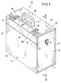
- FIG. 1 The example shown in Fig. 1 and in is in its entirety designated 10 carrying case designed like a pilot's case. It includes a floor, possibly also designed as a frame body 11, a rear wall 12, further two opposite one another Side walls 13 (in cases of the illustrated Art also called 'wedges'), and a front wall 14 and a two-part, from an inner lid flap 15 and an external part of this Cover part 16 existing closure arrangement.
- a floor possibly also designed as a frame body 11
- a rear wall 12 further two opposite one another Side walls 13 (in cases of the illustrated Art also called 'wedges')
- a front wall 14 and a two-part from an inner lid flap 15 and an external part of this Cover part 16 existing closure arrangement.
- the inner lid flap 15 has two Locks 17 and a pivoting handle 18, and the outside cover lid flap 16 'two Lock bolt 19 and an opening 20 for the penetration of the handle 18. Finally, at 21 are on the Side walls 13 attached brackets for removable if necessary Plug in a not shown Carrying strap designated.
- the front wall 14 is divided into a lower, fixed front wall part 22 and an upper to a horizontal axis 23 pivotable front wall part 24.
- the heights of the fixed front wall part 22 and of the movable front wall part 24 add up - approximately in the ratio 4/1 - to the total height of the carrying case 10.
- the upper movable front wall part 24 the connection between the fixed Front wall parts 22 and the inner lid flap 15 forth, the lid flap 15 and the front wall part 24 (at right angles to each other) rigid or - and although preferably as in the illustrated embodiment - About one in the closed state of the container case edge forming fold 55 or hinge can be movably connected.
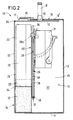
- FIG. 2 serves the interior of the container 25 to accommodate numerous for the operation of a portable computer, in particular a notebook or a rare one Laptops, suitable recordings.
- a portable computer in particular a notebook or a rare one Laptops, suitable recordings.
- partition 26 Through a vertical, longitudinally largely through the interior 25 of the case-like carrying case 10 extending partition 26 is a receiving space 28 for the front wall a computer 29 and then a recording room 30 created for a printer 31.
- Printer 31 in the manner described below in the stowed position shown in FIG. 2 or FIG. 6 are allowed on the basis of the usual today miniaturized construction the arrangement of further objects, so e.g. a power supply in the same compartment 30 below the respective printer 31. Also Printer cable, not shown, a mouse and the like. to let stow away there.
- Receiving compartment 28 To adapt the limited by the front wall 14 Receiving compartment 28 to the individual size of certain Brands or types of computers 29 are two molded articles 32 of substantially L-shaped basic shape as Adapter inserts provided. These are in the bottom Corners of the receiving compartment 28 inserted such that the computer 29 with its lower corner regions 33 each rests on a horizontal leg 34 and laterally stabilized by the vertical legs 35 is held in the receiving compartment 28. Should that Carrying case 10 for storing a computer 29 different sizes are used, the adapter inserts 32 exchanged for those of a different dimension. Incidentally, they are simple parts made of plastic, e.g. Foam.
- the partition 26, the receiving space 28 for the Computer 29 against the receiving space 30 for the printer 31 compartments, is as a one-piece and one-piece plate 36 executed.
- the plate 36 has on each long side at a distance from their lower edge 37 each axially extending axles 38 on a vertical section 39 of a Guide 40 can slide. In each of the carrying sidewalls 13 associated guide 30 engages only one such journal 38, but not the plate 36 itself.
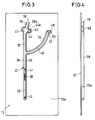
- a first peculiarity is that in the Movement path of each of the axle journals in the pull-out direction (Arrow 41) engages a limit stop 42 and a second in that the guide 40 has an insertion pocket 43 for the journal 39 with an underpinning Support bracket 44 and one overlapping it Shoulder 44a is assigned.
- control pin 45 one at the bottom of each Plate 36 from the same edge as the journal 38 and protrudes parallel to them, into the opening area an arcuate control link 46.
- This control link 46 guides the control pin 45 during the pivoting the plate 36 by about 90 °.
- the end area the control link 46 is a substantially arcuate-oblique extending control surface 47 and, thereon then, a pocket 48 closed at the end assigned.
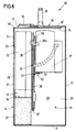
- a printer 31 continues in its operating position in front, as appropriate, the one to be operated horizontally Printer 31 in Fig. 5 or further back on the as Printing support plate 27 serving plate 36 rests like that printer 31 to be operated vertically in accordance with FIG. 7: Every printer finds its typical, without prejudice Operating position on the printer support plate 27 one against another Swiveled or swiveled back and locked accordingly stable position.
- the apex region 49 can be between the fixed lower front wall part 22 and the hinged upper front wall part 24 of the carrying case 10 also, and preferably in addition, the support serve the printer support plate 27.
- the support serve the printer support plate 27.
- a horizontally operable printer 31 can by means of self-adhesive surface fastener elements 51 (Velcro pads) firmly, although removable, immediately be attached to the printer support plate 27. Since the Partition / pressure support plate 26/27 with respect to one vertical operable printer 31 according to FIGS. 6 and 7 when changing from its stowed position (Fig. 6) in the Ready position (Fig. 7) and vice versa a relative Such a movement must be carried out Printer 31 by means of a hinge strap 52 for Swivel axis of the partition / pressure support plate 26/27 parallel pivot axis 53 attached.
- the hinge strap 52 is then preferred by means of double-sided adhesive tape strips attached to the partition / pressure support plate 26/27 and the printer 31 by means of the Velcro tape pads 51 detachably attached to the second hinge strip.
- the hinge strap 52 can be used as a plastic injection molded part with uniform hinge axis 53 e.g. formed in the form of a film hinge be.
- a spacing pad 54 e.g. a Foam cushion
- Velcro pads 51 are also provided here, one part of which is self-adhesive under the Printer 31 and the respective other part self-adhesive is attached to the pad 54.
- the partition / printer support plate 26/27 prepared at the factory be by equipping them with the appropriate required parts of fasteners 51 to 54.
- Um to leave the user free to choose the fastening parts 51 to 54 can also be made in total the carrying case for individual furnishing in Matched to the printer 31 used be.
Abstract
Description
Die Erfindung bezieht sich auf ein Tragebehältnis
wie Koffer, Tasche od. dgl. für einen tragbaren Computer,
einen Drucker und Zubehör gemäß dem Oberbegriff
des Anspruchs 1.The invention relates to a carrying case
such as suitcase, bag or the like for a portable computer,
a printer and accessories according to the preamble
of
Tragbare Computer, insbesondere sog. 'Notebooks', zeichnen sich vor allem durch ihre mobile Verwendbarkeit aus, woraus sich der Wunsch ableitet, geeignete Tragebehältnisse für den Computer, den zugehörigen Drucker und die zu ihrem Betrieb erforderlichen Zubehörteile verfügbar zu haben.Portable computers, especially so-called 'notebooks', are characterized above all by their mobile usability from what the wish derives, suitable Carrying cases for the computer, the associated Printers and the accessories necessary for their operation to have available.
Bekannt ist zunächst ein zweischaliger Koffer, in dessen Bodenteil Gefache untergebracht sind zur Aufnahme der Stromversorgung, der Kabel und der einzelnen Geräte, während der Deckelteil im geschlossenen Zustand des Koffers diese Teile schützt und ggf. noch Aufnahmetaschen für Papier, Dokumente, Schreibutensilien od.dgl. beherbergt. Die Handhabung des Koffers vollzieht sich so, daß sein Deckelteil vom Bodenteil abgenommen und dieser dann mit allen in ihm aufgenommenen Gerätschaften auf den Arbeitstisch gelegt wird, so daß am Computer gearbeitet werden kann. Dies erfordert auf dem Arbeitstisch eine relativ große Arbeitsfläche und wird auch aus anderen Gründen, z.B. wegen des Gesamtgewichts dieser Einheit, als störend empfunden.A two-shell suitcase is known, in whose bottom part compartments are accommodated for reception the power supply, the cables and the individual Devices while the lid part is closed the case protects these parts and, if necessary, still receiving pockets for paper, documents, writing utensils or the like. houses. The case is handled itself so that its cover part is removed from the bottom part and this one with all of it Equipment is placed on the work table so that can be worked on the computer. This requires on the work table has a relatively large work surface and is also used for other reasons, e.g. because of the total weight this unity, found to be disturbing.
Da die Hauptarbeit an dem Computer geleistet wird, der selbst nur geringen Platz beansprucht, wohingegen der über ein Druckeranschlußkabel mit ihm verbundene Drucker auch an anderer Stelle als auf dem Tisch seine Funktion erfüllen kann, ist ein Koffer entwickelt worden, der ebenfalls alle zum Betrieb des Computers und seines Zubehörs notwendigen Teile aufnimmt, dem jedoch für die Arbeit am Computer nur dieser entnommen wird, während die anderen Teile des EDV-Systems, so insbesondere der Drucker, im Koffer verbleiben.Since the main work is done on the computer, which itself takes up little space, whereas the one connected to it via a printer connection cable Printer elsewhere than on the table A case has been developed, which also all for the operation of the computer and of its accessories includes the necessary parts, however for work on the computer only this is removed, while the other parts of the computer system, so in particular the printer, remain in the case.
Ein aus DE 93 19 685 U1 bekannter Koffer weist einen Bodenrahmen, zwei Seitenwände, eine Frontwand und eine Rückwand sowie an seiner Oberseite einen Klappdeckel zum Verschluß des Koffers auf. Im Innern des Koffers sind mehrere Aufnahmefächer, so insbesondere eines für den Computer und eines für den Drucker vorgesehen. Die Frontwand ist am Bodenrahmen um eine unten liegende, horizontale Achse schwenkbar angelenkt und läßt sich aus der Lotrechten in eine Neigelage von etwa 45o nach vorn abklappen, nachdem der schalenartige Kofferdeckel geöffnet worden ist. Mit dem Ausklappen der Frontwand schwenkt der Computer teilweise aus dem Innenraum des Tragebehältnisses heraus und läßt sich so besser als bei senkrecht stehender Frontwand entnehmen.A case known from DE 93 19 685 U1 has a base frame, two side walls, a front wall and a rear wall and on its upper side a hinged lid for closing the case. Inside the case there are several storage compartments, in particular one for the computer and one for the printer. The front wall is hinged to the bottom frame about a horizontal axis lying below and can be folded down from the vertical into a tilt position of about 45 o after the shell-like case lid has been opened. When the front wall is unfolded, the computer partially swings out of the interior of the carrying case and can thus be removed better than when the front wall is vertical.
Das Aufnahmefach für den Computer wird von der ausklappbaren Frontwand einerseits und andererseits von einer Trennwand begrenzt, auf deren dem Computer abgewandten Seite weiter innen im Tragebehältnis der Drucker angeordnet ist. Diese Trennwand besteht aus einer in seitliche Halterungen eingesteckten Platte und einem schalenartigen Druckertragkörper, dessen Boden mit der Platte über Scharniere gelenkig verbunden ist. Sind der Kofferdeckel geöffnet, die Frontwand ausgeklappt und der Computer entnommen, läßt sich der Druckertragkörper um etwa 90o ebenfalls nach vorn und zum Teil aus dem Behälterinnenraum herausklappen, bis sein Boden auf Stützen auftrifft, die an der Innenseite der Frontwand besonders angebracht sind. Der Drucker steht in dieser seiner Bedienlage so bereit, daß er, wenn das Tragebehältnis auf dem Boden steht, vom sitzenden Computerbenutzer bedient werden kann, sofern er sich nur weit genug vornüber- und hinunterbeugt.The storage compartment for the computer is bounded on the one hand by the fold-out front wall and on the other hand by a partition wall, on the side of which facing away from the computer is arranged further inside in the carrying case of the printer. This partition consists of a plate inserted into side brackets and a bowl-like pressure support body, the bottom of which is hinged to the plate via hinges. If the case lid is open, the front wall is unfolded and the computer is removed, the printer support body can also be folded forward and partially out of the interior of the container by about 90 o until its bottom meets supports that are specially attached to the inside of the front wall. The printer is in this operating position ready so that when the carrying case is on the floor it can be operated by the seated computer user, provided he leans forward and downward enough.
Dieses bekannte kofferartige Tragebehältnis ist bereits erheblich vorteilhafter und in der Bedienung sinnvoller und geschickter eingerichtet als der eingangs beschriebene zweischalige Koffer, läßt aber noch einige Wünsche offen. So wird es beispielsweise noch als Nachteil empfunden, daß nach Öffnen des Deckels die Frontwand mit dem an ihr anliegenden Computer selbsttätig nach vorn abklappen und aufgrund des resultierenden Schwungmoments die Tasche zum Kippen bringen kann. Da der im vordersten Aufnahmefach nahe der ausklappbaren Frontwand im Behältnis aufgenommene Drucker zusammen mit der Frontwand herausklappt und mit seinem Boden auf der Innenseite der Frontwand liegt, ist es nicht ohne weiteres möglich, ihn lediglich mit einer Hand Zu ergreifen, was aufgrund des geringen Gewichts insbesondere von Notebooks an sich aber leicht geschehen könnte. Ein weiterer Nachteil besteht darin, daß im Bedienzustand des Behältnisses, also bei entnommenem Computer, ausgeklappter Frontwand und umgelegtem Druckertragkörper ein unbeabsichtigter Stoß gegen die Frontwand dazu führen kann, daß diese den Druckertragkörper und also den Drucker wieder aus der Bedienlage kippen kann, wodurch Schäden an der Einrichtung entstehen können. Durch das Umlegen des Druckertragkörpers aus der im wesentlichen lotrechten Drucker-Verstaulage in dessen horizontale Bedienlage ist überdies nur ein relativ bodennahes Arbeitsniveau des Druckers erreichbar.This well-known case-like carrying case is already considerably more advantageous and easy to use more sensible and cleverly furnished than the one at the beginning described two-shell suitcase, but still leaves some desires open. For example, it will still be felt as a disadvantage that after opening the lid Front wall with the computer attached to it automatically fold down and because of the resulting Momentum can cause the bag to tip. There the one in the front compartment near the fold-out one Printers accommodated in the front wall together folds out with the front wall and with its bottom open the inside of the front wall, it is not without further possible to close it with only one hand take what in particular because of its light weight of notebooks, however, is easy to do could. Another disadvantage is that in Operating state of the container, that is when the container is removed Computer, unfolded front wall and folded Pressure carrier an accidental impact against the Front wall can cause the printer support body and thus the printer out of the operating position can tip, causing damage to the device can. By folding the printer body from the essentially vertical printer stowed position in its horizontal operating position there is only one relatively low working level of the printer can be reached.
DE 195 06 740 C2 stellt mit dem Ziel, dem gegenüber nennenswerte Bedienungsvorteil zu erreichen, in dieser Hinsicht eine deutliche Verbesserung dar. Bei diesem Koffer ist der Druckertragkörper als Platte ausgebildet, die über eine horizontal Achse schwenkbar mit dem oberen Rand eines Trennwandteils verbunden ist. Die beiden in seitlichen Führungen vertikal verschieblichen Platten können ein Stück nach oben herausgezogen werden. Sobald die Druckertragplatte aus den Führungen freikommt, kann sie mit dem auf ihr befestigten Drucker aus dessen vertikaler Verstaulage in eine horizontale Gebrauchslage umgelegt werden. Die abgeklappte Druckertragplatte wird zwar auch hier unter Einbeziehung der Frontwand des Koffers in der Drucker-Betriebslage abgestützt, jedoch in besonderer Weise auf einem Scheitelbereich, der bei geöffnetem Behälter zwischen einem festen, unteren Frontwandteil und einem um eine horizontale Achse abklappbar an diesem angelenkten oberen Frontwandteil ausgebildet ist.DE 195 06 740 C2 contrasts with the goal to achieve significant operating advantage in this is a significant improvement this case, the pressure support body is designed as a plate, which can be swiveled along a horizontal axis the upper edge of a partition part is connected. The both vertically displaceable in side guides Plates can be pulled out a little upwards. Once the printer support plate out of the guides is released, it can with the printer attached to it from its vertical storage position into a horizontal one Use position be flipped. The folded printer support plate is here also with the involvement of Front wall of the case supported in the printer operating position, but in a special way on an apex area, the one with the container open fixed, lower front wall part and one around a horizontal Foldable axis on this articulated upper Front wall part is formed.
Wichtig bei dieser bekannten Ausführung ist es, daß Druckertragplatte und Drucker zunächst vom Boden des Behältnisses hochgezogen und der Drucker erst in einer wesentlich höheren Position in seine Betriebslage geschwenkt wird, so daß er auf einem ergonomisch angenehm bodenfernen Arbeitsniveau bereitsteht.It is important with this known design that that the printer support plate and printer are first off the floor of the container pulled up and the printer only in a much higher position in its operating position is pivoted so that it is ergonomically comfortable ground-level working level is available.
DE 195 06 740 C2 betrifft ein Tragebehältnis für einen Drucker, der in Verstaulage aufrecht aufbewahrt und transportiert und in einer erhöhten Stellung horizontal betrieben wird. Ein besonderes Problem, das mit den an sich sehr vorteilhaften Mitteln nach Patent DE 195 06 740 C2 allein nicht beherrschbar ist, werfen jedoch Drucker auf, die auch in Bedienlage aufrecht stehen. Ein prominentes Beispiel hierfür ist der Druckertyp HP 340 der 'DeskJet'-Familie der amerikanischen Herstellerfirma Hewlett Packard.DE 195 06 740 C2 relates to a carrying case for a printer that is kept upright when stowed and transported and in an elevated position horizontally is operated. A special problem with the very advantageous means according to patent DE 195 06 740 C2 alone cannot be controlled, throw however, printers that are upright even in the operator position stand. A prominent example of this is the Printer type HP 340 of the 'DeskJet' family of the American Manufacturing company Hewlett Packard.
Verglichen mit Druckern konventionellen Designs steht dieser Drucker praktisch aufrecht auf dem Rücken. An die Oberseite, die nun aber eine lotrechte Wand darstellt, kann ein Einzelblatteinzug angebracht werden, während sich im Boden, der nunmehr gegenüberliegenden Seitenwand, ein schlitzförmiger Papierauswurf befindet. Die bevorzugte Verstaulage für jeden Drucker ist wegen der optimalen Raumausnutzung stets eine aufrechte oder Hochkantlage, aber ein Drucker dieses Typs soll zwar auch aus seiner Verstaulage im Tragebehältnis in eine erhöhte Betriebsposition verbracht, darf jedoch nicht umgelegt werden.Compared to conventional design printers this printer stands practically upright on its back. To the top, which is now a vertical wall, a single sheet feeder can be attached, while in the ground, the now opposite Side wall, a slit-shaped paper ejection located. The preferred stowage location for any printer is because the optimal use of space always an upright or Upright, but a printer of this type is said to be also from its stowed position in the carrying case into a raised operating position, but must not be thrown.
Aus DE 296 01 928 U1 ist ein Tragebehältnis bekannt, das in geschickter Weise so weitergebildet ist, daß im Betrieb aufrecht stehende Drucker in ergonomisch günstiger Zuordnung zum Tragebehältnis bzw. zur Position des sitzenden Benutzers sicher betrieben werden können. Erreicht wird dies hier dadurch, daß innen an wenigstens einer sonstigen Wand des Drucker-Aufnahmefachs mindestens ein Druckerstützkörper vorgesehen ist, der aus einer wandnahen Nichtgebrauchslage in eine Unterstützungsstellung unter den Drucker bringbar ist, der in hochgezogener Stellung des Trennwandteils hierzu vorübergehend aus dem Bewegungsbereich des Druckerstützkörpers verlagerbar sowie anschließend auf den betriebsbereiten Druckerstützkörper auflagerbar ist und sich die Drucker-Gebrauchslage von der Drucker-Verstaulage vornehmlich durch ein erhöhtes Zugriffsniveau unterscheidet. In der Praxis bedeutet dies, daß der Drucker mit dem Druckertragkörper, an dem er gehalten ist, aus der behältertiefen Verstaulage hochgezogen wird, wobei er vorübergehend über seine Gebrauchslage hinaus gebracht wird, bis der mindestens eine Druckerstützkörper bereitgestellt ist, auf den er sodann ein kleines Stück zurückbewegt wird. Eine besonders einfache Möglichkeit, dies zu bewirken, kann bereits in einem kurzfristigen, geradlinigen 'Überheben' über den für seine Bereitstellung erforderlichen Bewegungsbereich des Druckerstützkörpers hinaus bestehen.DE 296 01 928 U1 is a carrying case known that trained in a clever way is that in operation, printers standing upright in ergonomic favorable allocation to the carrying case or Position of the seated user can be operated safely can. This is achieved here by the fact that inside on at least one other wall of the printer compartment at least one printer support body is provided is that from a non-use position close to the wall into a Support position can be brought under the printer, in the raised position of the partition part temporarily out of the range of movement of the printer support body relocatable and then to the operational printer support body can be stored and the printer usage position is different from the printer storage position primarily through an increased level of access differs. In practice, this means that the Printer with the printer support body to which it is held is pulled up from the deep storage position being, temporarily over its position of use is brought out until the at least one printer support body is provided, on which he then a small piece is moved back. A particularly simple one Possibility of doing this can already be found in a short-term, straightforward 'raising' over the range of motion required for its provision of the printer support body also exist.
Aufgabe der vorliegenden Erfindung ist nunmehr die Bereitstellung einer universellen Lösung für ein gattungsgemäßes Tragebehältnisses, das sowohl für horizontal als auch vertikal betriebene Drucker gleichermaßen geeignet ist.The object of the present invention is now that Provision of a universal solution for a generic Carrying case that is both for horizontal as well as vertically operated printers alike suitable is.
Die Lösung dieser Aufgabe ist im Anspruch 1 angegeben.
Demnach ist die Erfindung insbesondere dadurch
gekennzeichnet, daß die Trennwand einstückig ausgebildet
ist und ihrer Gesamtheit die Druckertragplatte ausbildet,
daß die Schwenkachse von Achszapfen definiert
ist, die über die Trennwandränder vorstehend in die
seitlichen Führungen eingreifen und daß die
Schwenkachse mit Abstand vom unteren bzw. hinteren
Trennwandrand angeordnet ist.The solution to this problem is specified in
Die nunmehr einteilige Druckertragplatte kann aufgrund fehlender Gelenkverbindungen der bislang zweiteiligen Ausführung insgesamt stabiler ausgeführt sein. Zugleich ist die Gesamtfläche der Druckertragplatte vergrößert, so daß jeder beliebige transportable Kleindrucker einen ihm am besten geeigneten Platz auf dieser Fläche finden kann. Durch die besondere Anordnung der Schwenkachse mit Abstand vom (in der Verstaulage) unteren bzw. (in der Betriebslage) hinteren Trennwandrand wird erreicht, daß sich die Druckertragplatte in der Bedienlage des Druckers auch zum inneren Bereich des Tragebehältnisses in Richtung auf deren Rückwand hin erstrecken kann und folglich nicht in statisch ungünstiger Weise zu weit nach vorn aus dem Tragebehältnis hinausragt.The now one-piece printer support plate can be due to missing joint connections of the two-part so far Execution to be more stable overall. At the same time is the total area of the printer support plate enlarged so that any portable small printer a most suitable place on this one Can find area. Due to the special arrangement of the Swivel axis at a distance from the bottom (in the stowed position) or (in the operating position) rear partition edge is achieved that the printer support plate in the Operating position of the printer also to the inner area of the Carrying case towards the rear wall can extend and consequently not in statically unfavorable Point too far forward out of the carrying case protrudes.
Zur Halterung eines insbesondere horizontal betriebenen Druckers auf der Druckertragplatte genügen beispielsweise selbstklebend angeheftete Abschnitte eines Flächenreißverschlusses (einem aus Flauschband und Hakenband bestehenden Klettverschlusses). Solche, auch Klettenpads genannte trennbare Befestigungsmittel kann man auch bei einem sowohl vertikal verstaubaren als auch vertikal bedienbaren Drucker vorsehen, wobei zusätzlich mittels einer Scharnieranordnung zwischen Drucker und Druckertragplatte dafür gesorgt ist, daß, während der Drucker seine vertikale Lage, die er verstaut einnimmt, auch in der Betriebsstellung, wenngleich auf höherem Arbeitsniveau, beibehält, die Druckertragplatte von der lotrechten Drucker-Verstaulage in eine horizontale Drucker-Bereitschaftsstellung verschwenkt werden kann.To hold a particularly horizontal operated printer on the printer support plate are sufficient for example, self-adhesive sections a surface zip (one made of fleece tape and hook tape existing Velcro). Such, separable fastening means also called Velcro pads can also be stowed vertically in one as well as vertically operable printers, whereby additionally by means of a hinge arrangement between Printer and printer support plate ensure that, while the printer is in its vertical position, which it stows occupies, even in the operating position, albeit at a higher level of work that maintains Printer support plate from the vertical printer storage position to a horizontal printer standby can be pivoted.
Im Zusammenhang mit einem vertikal bedienbaren Drucker ist es von Bedeutung, daß entsprechend der Erfindung ansonsten keine besonderen Mittel zu seiner Halterung oder zur Einhaltung seiner Bedienlage, wie der gesonderte Druckerstützkörper entsprechend DE 296 01 928 U1, mehr erforderlich sind, da deren Funktion die großflächige, einteilige Druckertragplatte mit übernehmen kann.In connection with a vertically operable It is important for printers that according to the Otherwise no special means to its invention Bracket or to maintain its operating position, such as the separate printer support body according to DE 296 01 928 U1, more are required because of their function the large, one-piece printer support plate with can take over.
Zur alleinigen oder zusätzlichen Stabilisierung der Druckerbetriebslage kann die aus der Verstaulage als Trennwand in Druckerbedienlage herausgeschwenkte Druckertragplatte sich auf dem Scheitelbereich eines ersten, feststehenden und eines zweiten, nach außen abklappbaren Frontwandteils des Tragebehälnisses abstützen, wie es im Prinzip bereits in DE 195 06 740 C2 und in DE 296 01 928 U1 dargestellt und beschrieben ist. Im Rahmen vorliegender Erfindung ist jedoch in erster Linie daran gedacht, eine solche Stütze ggf. ergänzend vorzusehen, wohingegen entsprechend einem bevorzugten Ausführungsbeispiel die Trennwand als ausgeschwenkte Druckertragplatte - vorzugsweise selbsttätig - in der Druckerbedienlage verriegelbar sein soll. Erreicht wird dies dadurch, daß jeder Führung eine Einschubtasche für den Achszapfen mit einer ihn unterfangenden Auflagerstütze zugeordnet ist. Nach dem Heraufziehen und Umschwenken brauch die Druckertragplatte mit ihren Achszapfen dann lediglich - z.B. nach hinten - in diese Einschubtaschen eingeschoben zu werden, um in Vertikalrichtung sicher abgefangen und gelagert zu sein.For sole or additional stabilization the printer operating position can be from the stowed position swung out as a partition in the printer operating position Printer support plate itself on the crown area first, fixed and a second, outward hinged front wall part of the carrying case support, as it is already in principle DE 195 06 740 C2 and shown in DE 296 01 928 U1 and is described. Within the scope of the present invention is primarily thought of, however If necessary, provide additional support, whereas accordingly a preferred embodiment, the partition as a swung out pressure support plate - preferably automatic - lockable in the printer operating position should be. This is achieved by everyone Carrying an insertion pocket for the axle journal is assigned to a support bracket under it. After pulling up and swiveling, you need the Printer support plate with its axle journals then only - e.g. to the rear - inserted into these pockets to be safely intercepted in the vertical direction and to be stored.
Vereinfacht werden kann diese Handhabung der Sicherung dadurch, daß in die Bewegungsbahn der Achszapfen in Auszugsrichtung ein Begrenzungsanschlag eingreift, der für eine lagegerechte Zuordnung der Einschubtasche sorgt, ohne daß hierzu besondere Aufmerksamkeit des Benutzers erforderlich ist.This handling can be simplified Secured by the fact that in the movement path of the journal a limit stop engages in the pull-out direction, that for a correct allocation of the insert pocket provides without special attention of the user is required.
Der Bedienungskomfort läßt sich noch steigern, wenn entsprechend einem weiteren Erfindungsmerkmal der Führung eine Steuerkulisse zugeordnet ist, die jeweils einen vom Achszapfen beabstandeten Steuerzapfen führt. Dabei kann der Steuerkulisse wiederum eine Steuerfläche für den Steuerzapfen zugeordnet sein, die gegen Ende der Schwenkbewegung der Trennwand deren Achszapfen auf die Auflagerstütze leitet. Hierdurch gestaltet sich das Verlagern der Trennwand aus der Transportstellung als Druckertragplatte in die Druckerbedienlage nach dem einfachen Prinzip des Sehens und Gebrauchens. Denn es muß nichts weiter getan werden, als die Trennwand mit dem Drucker zu ergreifen, nach oben zu ziehen sowie nach vorn herunterzuschwenken, bis die gebrauchsfähige und sogleich verriegelte Lage für den Drucker automatisch erreicht ist. The ease of use can be increased even more, if according to a further feature of the invention Leadership is associated with a tax backdrop, each leads a control pin spaced from the axle pin. The control link can in turn be a control surface for the control pin that will be assigned towards the end the pivoting movement of the partition on its journal the support column guides. This is how it works Relocate the partition from the transport position as Printer support plate in the printer operating position after simple principle of seeing and using. For it nothing needs to be done other than with the partition grasp the printer, pull up and swivel forward until the usable and immediately locked position for the printer automatically is reached.
Zur zusätzlichen Erhöhung der Stabilität der Druckertragplatte in der Druckergebrauchslage kann der Steuerkulisse eine Auflagerfläche für den Steuerzapfen in der Bedienstellung der Trennwand zugeordnet sein, so daß die Druckertragplatte im Bereich der - dann hinteren - Steuerzapfen auch in Vertikalrichtung sicher abgestützt ist.To further increase the stability of the The printer support plate in the printer use position can Control link a support surface for the control pin be assigned in the operating position of the partition, so that the printer support plate in the area of the - then rear - Control pin also safe in the vertical direction is supported.
Zum leichten Einbau und auch Austausch der Trennwand/Druckertragplatte ist vorgesehen, daß die Führung neben dem Begrenzungsanschlag in einer zur Längsrichtung des Führungskanals unter einem Winkel abweichenden Richtung offen ist. Durch diese Öffnungen bzw. offenen Kanäle können die Achszapfen und die Steuerzapfen der Trennwand/Druckertragplatte auf einfachste Weise in die Führungen eingesteckt oder aus ihnen herausgezogen werden.For easy installation and also replacement of the partition / printer support plate it is intended that the leadership next to the limit stop in one to the longitudinal direction of the guide channel deviating at an angle Direction is open. Through these openings or open Channels can be the axle journal and the control journal of the Partition / printer support plate in the simplest way Guides are inserted or pulled out of them.
Bezüglich einer einfachen Gestaltung des Tragebehältnisses und der Mittel zu Führung und Festlegung der Trennwand/Druckertragplatte ist vorteilhafterweise noch vorgesehen, daß sämtliche Führungen und Kulissen einstückig-stoffschlüssige Bestandteile von als Spritzgießbauteilen ausgebildeten Seitenwänden (sog. Keilen) des Tragebehältnisses sind.Regarding a simple design of the carrying case and the means to guide and determine the Partition / pressure support plate is advantageously still provided that all guides and backdrops integrally-integral Components of as injection molded components trained side walls (so-called wedges) of the carrying case.
Im übrigen versteht sich die Erfindung am besten
aus ihrer nachfolgenden Beschreibung anhand eines in
den Zeichnungen dargestellten Ausführungsbeispiels.
Darin zeigen:
- Fig. 1
- eine Ansicht des geschlossenen Tragebehältnisses,
- Fig. 2
- einen Längsschnitt durch das Tragebehältnis entsprechend der Schnittangabe II-II in Fig. 1, mit einem horizontal zu bedienenden Drucker in Verstaulage,
- Fig. 3
- eine Innenansicht auf eine Seitenwand des Tragebehältnisses mit den Führungsanordnungen für die Verlagerung und Abstützung der Trennwand,
- Fig. 4
- eine Seitenansicht zu Fig. 3,
- Fig. 5
- einen Längsschnitt durch das geöffnete Tragebehältnis mit aus ihm bereits entnommenem Computer und aus seiner Verstaulage in Bedienlage umgelegtem, horizontal zu bedienenden Drucker,
- Fig. 6
- eine Fig. 2 entsprechende Darstellung mit einem verstauten, vertikal zu bedienenden Drucker, und
- Fig. 7
- eine Fig. 5 entsprechende Darstellung des vertikal zu bedienenden Druckers aus Fig. 6 in dessen Bedienposition.
In it show:
- Fig. 1
- a view of the closed carrying case,
- Fig. 2
- 2 shows a longitudinal section through the carrying container according to the section II-II in FIG. 1, with a printer to be operated horizontally in the stowed position,
- Fig. 3
- an interior view of a side wall of the carrying case with the guide arrangements for the displacement and support of the partition,
- Fig. 4
- 3 shows a side view of FIG. 3,
- Fig. 5
- 2 shows a longitudinal section through the opened carrying case with the computer already removed from it and from its stowed position in the operating position, the printer to be operated horizontally,
- Fig. 6
- a corresponding Fig. 2 with a stowed, vertically operated printer, and
- Fig. 7
- a representation corresponding to FIG. 5 of the printer to be operated vertically from FIG. 6 in its operating position.
Das in Fig. 1 beispielhaft dargestellte und in
seiner Gesamtheit mit 10 bezeichnete Tragebehältnis ist
nach Art eines Pilotenkoffers gestaltet. Es umfaßt
einen, ggf. auch als Rahmenkörper ausgestalteten, Boden
11, eine Rückwand 12, ferner zwei einander gegenüberliegende
Seitenwände 13 (bei Koffern der dargestellten
Art auch 'Keile' genannt), sowie eine Frontwand 14 und
eine zweiteilige, aus einer innenliegenden Deckelklappe
15 und einem diese teilweise überfangenden außenliegenden
Deckelteil 16 bestehende Verschlußanordnung.The example shown in Fig. 1 and in
is in its entirety designated 10 carrying case
designed like a pilot's case. It includes
a floor, possibly also designed as a
Die innenliegende Deckelklappe 15 weist zwei
Schlösser 17 sowie einen schwenkbaren Griff 18 auf, und
die außenliegende Überfall-Deckelklappe 16' zwei
Schließriegel 19 und einen Durchbruch 20 für den Durchgriff
des Griffes 18. Mit 21 schließlich sind an den
Seitenwänden 13 angebrachte Halterungen zum ggf. wiederentfernbaren
Anstecken eines nicht weiter dargestellten
Tragegurtes bezeichnet.The
Die Frontwand 14 ist unterteilt in einen unteren,
feststehenden Frontwandteil 22 und einen oberen, um
eine horizontale Achse 23 schwenkbaren Frontwandteil
24. Die Höhen des feststehenden Frontwandteils 22 und
des beweglichen Frontwandteils 24 addieren sich - etwa
im Verhältnis 4/1 - zur Gesamthöhe des Tragebehältnisses
10. Im übrigen stellt der obere bewegliche Frontwandteil
24 die Verbindung zwischen den feststehenden
Frontwandteilen 22 und der innen liegenden Deckelklappe
15 her, wobei die Deckelklappe 15 und der Frontwandteil
24 (im rechten Winkel zueinander) starr oder aber - und
zwar bevorzugt wie beim dargestellten Ausführungsbeispiel
- über eine im geschlossenen Zustand des Behältnisses
kofferkantenbildende Falzung 55 oder Scharnierung
beweglich miteinander verbunden sein können.The
Wie sich aus dem Längsschnitt der Fig. 2 ergibt,
dient das Behälterinnere 25 zur Aufnahme zahlreicher,
für den Betrieb eines tragbaren Computers, insbesondere
eines Notebooks oder auch eines seltener gewordenen
Laptops, geeignete Aufnahmen. Durch eine vertikale,
sich längs weitestgehend durch den Innenraum 25 des
kofferartigen Tragebehältnisses 10 erstreckende Trennwand
26 ist frontwandseitig ein Aufnahmeraum 28 für
einen Computer 29 und daran anschließend ein Aufnahmeraum
30 für einen Drucker 31 geschaffen.As can be seen from the longitudinal section in FIG. 2,
serves the interior of the
Drucker 31, die in nachfolgend beschriebener Weise
in der in Fig. 2 bzw. Fig. 6 dargestellten Verstaulage
aufgenommen sind, gestatten aufgrund der heute üblichen
miniaturisierten Bauweise die Anordnung weiterer Gegenstände,
so z.B. eines Netzgerätes in demselben Aufnahmefach
30 unterhalb des jeweiligen Druckers 31. Auch
nicht dargestellte Druckerkabel, eine Maus u.dgl. lassen
sich dort verstauen.
Zur Anpassung des von der Frontwand 14 begrenzten
Aufnahmefachs 28 an die individuelle Größe bestimmter
Marken oder Typen von Computern 29 sind zwei Formkörper
32 von im wesentlichen L-förmiger Grundgestalt als
Adapter-Einlagen vorgesehen. Diese werden in die unteren
Ecken des Aufnahmefachs 28 derart eingelegt, daß
der Computer 29 mit seinen unteren Eckbereichen 33
jeweils auf einem Horizontalschenkel 34 aufliegt und
seitlich durch die vertikalen Schenkel 35 lagestabilisiert
in dem Aufnahmefach 28 gehalten ist. Soll das
Tragebehältnis 10 zur Aufbewahrung eines Computers 29
abweichender Größe dienen, werden die Adapter-Einlagen
32 gegen solche entsprechend anderer Dimension ausgetauscht.
Es handelt sich im übrigen um einfache Teile
aus Kunststoff, z.B. Schaumstoff.To adapt the limited by the
Vorteilhaft ist zunächst, wenn der Computer 29,
wie es Fig. 2 veranschaulicht, möglichst hoch im Innenraum
des Behältnisfachs 28 bereitgehalten wird, damit
sich, wenn der Koffer geöffnet und der obere Frontwandteil
24 nach außen abgeklappt ist, der sich Computer 29
an seinem oberen Rand mit einer Hand leicht ergreifen
und aus dem Koffer herausnehmen läßt.It is advantageous first of all if the
Die Trennwand 26, die den Aufnahmeraum 28 für den
Computer 29 gegen den Aufnahmeraum 30 für den Drucker
31 abteilt, ist als einteilige und einstückige Platte
36 ausgeführt. An jeder Längsseite weist die Platte 36
mit Abstand von ihrem unteren Rand 37 jeweils einen
sich in Plattenrichtung länglich erstreckenden Achszapfen
38 auf, der in einem vertikalen Abschnitt 39 einer
Führung 40 gleiten kann. In jeweils eine jeder Tragebhältnis-Seitenwand
13 zugeordneten Führung 30 greift
jeweils nur ein solcher Achszapfen 38 ein, nicht aber
die Platte 36 selbst.The
Weiter oben bildet die Führung 40 im Anschluß an
ihren lineare Führungsabschnitt 39 ein Schwenklager 39a
für den Achszapfen 38 aus, das einige Besonderheiten
aufweist, wie schon seine eigentümliche Form zeigt,
wozu zum besseren Verständnis auf Fig. 3 verwiesen
wird, die dieser Führung und weiteren Erfindungsmerkmalen
in diesem Zusammenhang besonders gewidmet ist. Zu
beachten ist dabei, daß jede der beiden Seitenwände in
spiegelverkehrter Anordnung gleich gestaltet ist. Further up forms the
Eine erste Besonderheit besteht darin, daß in die
Bewegungsbahn jedes der Achszapfen in Auszugsrichtung
(Pfeil 41) ein Begrenzungsanschlag 42 eingreift und
eine zweite darin, daß der Führung 40 eine Einschubtasche
43 für den Achszapfen 39 mit einer ihn unterfangenden
Auflagerstütze 44 sowie einer ihn übergreifenden
Schulter 44a zugeordnet ist.A first peculiarity is that in the
Movement path of each of the axle journals in the pull-out direction
(Arrow 41) engages a
Hieraus resultiert, daß die die Trennwand 26 darstellenden
Platte 36 einfach soweit nach oben gezogen
werden kann, bis ihr jeweiliger Achszapfen 38 an dem
Auszugsweg-Begrenzungsanschlag 42 anstößt. Wird dann
die Platte 36 - bezüglich der Zeichnung entgegen dem
Uhrzeigersinn - verschwenkt, können die aufgrund der
Verschwenkung sodann in eine im wesentlichen horizontale
Lage verbrachten Achszapfen 38 in die jeweilige
Einschubtasche 43 eingeschoben werden. Die Platte 36
befindet sich jetzt in ihrer Funktion als Druckertragplatte
27 in der in Fig. 5 bzw. Fig. 7 gezeigten
Drucker-Bedienlage.The result of this is that the
Um diese Handhabung und auch die gegenläufige beim
Zurückschwenken der Platte 36 von ihrer äußeren Position
als Druckertragplatte 27 in ihre tragebehälterinnere
Lage als Trennwand 27 zu vereinfachen, sind Maßnahmen
getroffen, diese Schwenk- und Schiebevorgänge
quasi automatisch zu steuern.To this handling and also the opposite with
Swinging the
Eine erste dieser Maßnahmen besteht in dem bereits
erwähnten Auszugs-Begrenzungsanschlag 42. Sobald die
Achszapfen 38 daran anstoßen, gelangen nämlich Steuerzapfen
45, von denen jeweils einer am unteren Ende der
Platte 36 vom jeweils selben Rand wie die Achszapfen 38
und parallel zu ihnen absteht, in den Öffnungsbereich
einer kreisbogenförmigen Steuerkulisse 46. Diese Steuerkulisse
46 führt den Steuerzapfen 45 während der Verschwenkung
der Platte 36 um etwa 90°. Dem Endbereich
der Steuerkulisse 46 ist eine im wesentlichen bogenförmig-schräg
verlaufende Steuerfläche 47 und, daran
anschließend, eine endseitig geschlossene Tasche 48
zugeordnet. Beim Auftreffen des Steuerzapfens 45 auf
die Steuerfläche 47 wird der Steuerzapfen 45 gleichsam
selbsttätig in die quer verlaufende Tasche 48 hinein
geführt, in der er nach oben und unten hin von den Wandungen
der Kulisse 46 sicher abgestützt bzw. übergriffen
ist. Gleichzeitig bewirkt die dabei durch Verschwenken
der Platte 36 erzwungene Querbewegung aber
auch, daß die Achszapfen 38 in ihre eigenen Aufnahmetaschen
43 hinein geleitet werden, worin auch sie gegen
Verlagerungen nach oben und nach unten gesichert aufgenommen
sind.A first of these measures already exists
mentioned
Ob nun ein Drucker 31 in seiner Bedienlage weiter
vorn wie zweckmäßig der horizontal zu bedienende
Drucker 31 in Fig. 5 oder weiter hinten auf der als
Druckertragplatte 27 dienenden Platte 36 ruht wie der
senkrecht zu betreibende Drucker 31 entsprechend Fig.
7: Jeder Drucker findet unbeschadet seiner typischen
Bedienlage auf der Druckertragplatte 27 eine gegen weiteres
Schwenken oder Rückschwenken verriegelte und entsprechend
stabile Position. Whether a
Zusätzlich kann der Scheitelbereich 49 zwischen
dem festen unteren Frontwandteil 22 und dem abklappbaren
oberen Frontwandteil 24 des Tragebehältnisses 10
auch, und zwar bevorzugt zusätzlich, der Unterstützung
der Druckertragplatte 27 dienen. Bei weit vorn angeordneten
Druckern wie bei dem Drucker 31 nach Fig. 5
könnte allein diese Auflage genügen. Allerdings ist die
Abstützung der Zapfen 38 und 45 in den Taschen 43 und
48 sehr wohl vorteilhaft, weil dadurch vor allem auch
eine Sperre gegen Zurückschwenken der Druckertragplatte
gebildet ist, so daß unbeabsichtigte Stöße vorn unter
die Druckertragplatte 27 keinen Schaden zur Folge haben
können.In addition, the
Um die Trennwand/Druckertragplatte 26/27 auf einfache
Weise in das Tragebehältnis 10 einstecken und
auch aus ihm entfernen zu können, weist die Führung 40
oberhalb des Schwenklagers 39a einen nach oben offenen
Führungsabschnitt 50 auf.To the partition /
Im übrigen sind beim Ausführungsbeispiel die Führung
40 und die Kulisse 46 durch auf der Innenfläche
13a einer Tragehältnis-Seitenwand 13 erhabene, die Führungs- und Bewegungsbahnen begrenzende bzw. definierende
Rippen 56 und diese mit den Seitenwänden 13 einstückig-stoffschlüssig
ausgebildet. Die Figuren 3 und 4
lassen dies besonders anschaulich erkennen.Incidentally, in the embodiment, the
Ein horizontal bedienbarer Drucker 31 kann mittels
selbstklebender Flächenhaftverschlußelemente 51
(Klettenpads) fest, wenngleich abnehmbar, unmittelbar
auf der Druckertragplatte 27 angebracht werden. Da die
Trennwand/Druckertragplatte 26/27 bezüglich eines vertikal
bedienbaren Drucker 31 entsprechend Fig. 6 und 7
beim Wechsel von dessen Verstaulage (Fig. 6) in die
Bereitschaftsstellung (Fig. 7) und umgekehrt eine relative
Schwenkbewegung ausführen muß, ist ein solcher
Drucker 31 mittels eines Scharnierbandes 52 mit zur
Schwenkachse der Trennwand/Druckertragplatte 26/27
paralleler Schwenkachse 53 befestigt. Das Scharnierband
52 ist dann bevorzugt mittels doppelseitiger Klebebandstreifen
an der Trennwand/Druckertragplatte 26/27 befestigt
und der Drucker 31 mittels der Klettenbandpads 51
abnehmbar an der zweiten Scharnierleiste angebracht.
Das Scharnierband 52 kann als Kunststoffspritzgießteil
mit werkstoffeinheitlich-stoffschlüssiger Scharnierachse
53 z.B. in Form eines Filmscharniers ausgebildet
sein.A horizontally
Auf der dem Scharnierband 52 gegenüberliegenden
Schmalseite des Druckers 31 kann dieser zur Wahrung
einer genau bestimmten, z.B. exakt horizontalen Position
durch eine distanzierende Unterlage 54, z.B. ein
Schaumstoffkissen, unterfüttert sein. Bedarfsweise können
auch hier noch Klettenpads 51 vorgesehen sein,
deren jeweils einer Teil selbstklebend unter dem
Drucker 31 und der jeweilige andere Teil selbstklebend
auf der Unterlage 54 befestigt ist.On the
Je nach Bestimmung für einen horizontal oder vertikal
zu betreibenden Drucker 31 kann die Trennwand/Druckertragplatte
26/27 werkseitig vorbereitet
sein durch Ausrüstung mit den jeweils entsprechend
benötigten Teilen von Befestigungsteilen 51 bis 54. Um
dem Benutzer die wahlfreie Einrichtung zu überlassen,
können die Befestigungsteile 51 bis 54 auch insgesamt
dem Tragebehältnis zur individuellen Einrichtung in
Abstimmung auf den verwendeten Drucker 31 beigelegt
sein.Depending on the destination for one horizontally or vertically
Claims (10)
Applications Claiming Priority (2)
| Application Number | Priority Date | Filing Date | Title |
|---|---|---|---|
| DE19643040 | 1996-10-18 | ||
| DE19643040A DE19643040C1 (en) | 1996-10-18 | 1996-10-18 | Computer system case |
Publications (3)
| Publication Number | Publication Date |
|---|---|
| EP0837384A2 true EP0837384A2 (en) | 1998-04-22 |
| EP0837384A3 EP0837384A3 (en) | 1998-04-29 |
| EP0837384B1 EP0837384B1 (en) | 2003-01-15 |
Family
ID=7809117
Family Applications (1)
| Application Number | Title | Priority Date | Filing Date |
|---|---|---|---|
| EP97115862A Expired - Lifetime EP0837384B1 (en) | 1996-10-18 | 1997-09-12 | Carrying case for EDP system |
Country Status (5)
| Country | Link |
|---|---|
| EP (1) | EP0837384B1 (en) |
| AT (1) | ATE231253T1 (en) |
| DE (2) | DE19643040C1 (en) |
| DK (1) | DK0837384T3 (en) |
| ES (1) | ES2188837T3 (en) |
Cited By (3)
| Publication number | Priority date | Publication date | Assignee | Title |
|---|---|---|---|---|
| EP1238601A1 (en) * | 2001-03-09 | 2002-09-11 | Orlan Holding S.A. | Suitcase particularly adapted to carry a computer and its accessories |
| EP1255181A2 (en) * | 2001-04-23 | 2002-11-06 | Winfo Data GmbH | Stowing device for stowing electrical apparatuses in mobile units |
| CN103275561A (en) * | 2013-05-22 | 2013-09-04 | 袁伟 | Environmentally-friendly water-based nanometer color paste and preparation method thereof |
Families Citing this family (3)
| Publication number | Priority date | Publication date | Assignee | Title |
|---|---|---|---|---|
| WO1999055189A2 (en) | 1998-04-24 | 1999-11-04 | Mp Michael Pfeiffer Design & Marketing Gmbh | Suitcase |
| DE29807481U1 (en) * | 1998-04-24 | 1999-09-02 | Mp Michael Pfeiffer Design & M | Trolley case |
| DE10310890B4 (en) * | 2003-03-11 | 2008-01-31 | PARAT-Werk Schönenbach GmbH + Co. KG | Device for mounting a device on a plate, in particular a printer on a printer tray to be arranged in a carrying case, a suitcase or the like |
Citations (3)
| Publication number | Priority date | Publication date | Assignee | Title |
|---|---|---|---|---|
| DE29601928U1 (en) * | 1996-02-07 | 1996-04-11 | Parat Werk Schoenenbach Gmbh | Computer system case |
| DE19506740C1 (en) * | 1995-02-27 | 1996-04-25 | Parat Werk Schoenenbach Gmbh | Carrying case for use with portable computer based system |
| DE29618106U1 (en) * | 1996-10-18 | 1996-12-12 | Parat Werk Schoenenbach Gmbh | Computer system case |
Family Cites Families (1)
| Publication number | Priority date | Publication date | Assignee | Title |
|---|---|---|---|---|
| DE9319685U1 (en) * | 1993-12-21 | 1994-04-07 | Felke Bernhard | Case-like container for holding mobile data processing devices |
-
1996
- 1996-10-18 DE DE19643040A patent/DE19643040C1/en not_active Expired - Fee Related
-
1997
- 1997-09-12 ES ES97115862T patent/ES2188837T3/en not_active Expired - Lifetime
- 1997-09-12 EP EP97115862A patent/EP0837384B1/en not_active Expired - Lifetime
- 1997-09-12 AT AT97115862T patent/ATE231253T1/en not_active IP Right Cessation
- 1997-09-12 DK DK97115862T patent/DK0837384T3/en active
- 1997-09-12 DE DE59709138T patent/DE59709138D1/en not_active Expired - Fee Related
Patent Citations (3)
| Publication number | Priority date | Publication date | Assignee | Title |
|---|---|---|---|---|
| DE19506740C1 (en) * | 1995-02-27 | 1996-04-25 | Parat Werk Schoenenbach Gmbh | Carrying case for use with portable computer based system |
| DE29601928U1 (en) * | 1996-02-07 | 1996-04-11 | Parat Werk Schoenenbach Gmbh | Computer system case |
| DE29618106U1 (en) * | 1996-10-18 | 1996-12-12 | Parat Werk Schoenenbach Gmbh | Computer system case |
Cited By (5)
| Publication number | Priority date | Publication date | Assignee | Title |
|---|---|---|---|---|
| EP1238601A1 (en) * | 2001-03-09 | 2002-09-11 | Orlan Holding S.A. | Suitcase particularly adapted to carry a computer and its accessories |
| EP1255181A2 (en) * | 2001-04-23 | 2002-11-06 | Winfo Data GmbH | Stowing device for stowing electrical apparatuses in mobile units |
| EP1255181A3 (en) * | 2001-04-23 | 2004-01-21 | Winfo Data GmbH | Stowing device for stowing electrical apparatuses in mobile units |
| CN103275561A (en) * | 2013-05-22 | 2013-09-04 | 袁伟 | Environmentally-friendly water-based nanometer color paste and preparation method thereof |
| CN103275561B (en) * | 2013-05-22 | 2015-06-03 | 袁伟 | Environmentally-friendly water-based nanometer color paste and preparation method thereof |
Also Published As
| Publication number | Publication date |
|---|---|
| ES2188837T3 (en) | 2003-07-01 |
| DE19643040C1 (en) | 1998-04-23 |
| DE59709138D1 (en) | 2003-02-20 |
| EP0837384B1 (en) | 2003-01-15 |
| EP0837384A3 (en) | 1998-04-29 |
| ATE231253T1 (en) | 2003-02-15 |
| DK0837384T3 (en) | 2003-02-24 |
Similar Documents
| Publication | Publication Date | Title |
|---|---|---|
| EP2994274B1 (en) | Container assembly | |
| EP0772411B1 (en) | Workstation | |
| WO2016116425A1 (en) | Suitcase, especially a pilot suitcase | |
| EP1309470A1 (en) | System for storing a load in a vehicle | |
| EP0837384B1 (en) | Carrying case for EDP system | |
| DE19506740C1 (en) | Carrying case for use with portable computer based system | |
| DE2839745A1 (en) | SEWING MACHINE FURNITURE WITH A LOWERING DEVICE | |
| DE10153492A1 (en) | Table, especially school desk, has work surface and a chassis, bearer(s) for flat screen display designed to enable display to be moved between stowed position and working position | |
| DE202005003818U1 (en) | Case for transporting at least one electronic device, e.g. computer or projector, has panel pivotably joined to lid that can adopt position with lid raised in which electronic device on panel can be arranged in operating position | |
| WO2018177637A1 (en) | Transport container | |
| DE19604407C2 (en) | Computer system case | |
| DE4101238A1 (en) | Deck cargo space for freighter - has removable frame walls for container | |
| AT407600B (en) | BRIEFCASE | |
| DE19545652C2 (en) | Mobile work facility with external connection to a computer unit | |
| EP2412267B1 (en) | Transportable container in the form of a suitcase | |
| EP0629367B1 (en) | Storage container for storing objects in several containers | |
| EP0758110B1 (en) | Carrying case for EDP system | |
| DE10213303B4 (en) | Suitcases, in particular pilot cases | |
| DE10331071B4 (en) | Computer workstation in a vehicle, especially in a passenger car | |
| DE1920633C3 (en) | sewing machine | |
| DE19837725C1 (en) | Waste collector integral to kitchen cupboard | |
| DE929847C (en) | Facility for storage of visual files | |
| DE102007012215B4 (en) | Device for transporting general cargo | |
| DE202019005120U1 (en) | fair Trolley | |
| DE729360C (en) | Typing and typewriter table |
Legal Events
| Date | Code | Title | Description |
|---|---|---|---|
| PUAI | Public reference made under article 153(3) epc to a published international application that has entered the european phase |
Free format text: ORIGINAL CODE: 0009012 |
|
| PUAL | Search report despatched |
Free format text: ORIGINAL CODE: 0009013 |
|
| AK | Designated contracting states |
Kind code of ref document: A2 Designated state(s): AT BE CH DE DK ES FI FR GB IE IT LI LU NL SE |
|
| AX | Request for extension of the european patent |
Free format text: AL;LT;LV;RO;SI |
|
| AK | Designated contracting states |
Kind code of ref document: A3 Designated state(s): AT BE CH DE DK ES FI FR GB GR IE IT LI LU MC NL PT SE |
|
| AX | Request for extension of the european patent |
Free format text: AL;LT;LV;RO;SI |
|
| 17P | Request for examination filed |
Effective date: 19980518 |
|
| AKX | Designation fees paid |
Free format text: AT BE CH DE DK ES FI FR GB GR IE IT LI LU |
|
| RBV | Designated contracting states (corrected) |
Designated state(s): AT BE CH DE DK ES FI FR GB GR IE IT LI LU |
|
| RBV | Designated contracting states (corrected) |
Designated state(s): AT BE CH DE DK ES FI FR GB IE IT LI LU NL SE |
|
| GRAG | Despatch of communication of intention to grant |
Free format text: ORIGINAL CODE: EPIDOS AGRA |
|
| 17Q | First examination report despatched |
Effective date: 20020228 |
|
| GRAG | Despatch of communication of intention to grant |
Free format text: ORIGINAL CODE: EPIDOS AGRA |
|
| GRAH | Despatch of communication of intention to grant a patent |
Free format text: ORIGINAL CODE: EPIDOS IGRA |
|
| GRAH | Despatch of communication of intention to grant a patent |
Free format text: ORIGINAL CODE: EPIDOS IGRA |
|
| GRAA | (expected) grant |
Free format text: ORIGINAL CODE: 0009210 |
|
| AK | Designated contracting states |
Kind code of ref document: B1 Designated state(s): AT BE CH DE DK ES FI FR GB IE IT LI LU NL SE |
|
| REG | Reference to a national code |
Ref country code: GB Ref legal event code: FG4D Free format text: NOT ENGLISH Ref country code: CH Ref legal event code: EP |
|
| REG | Reference to a national code |
Ref country code: IE Ref legal event code: FG4D Free format text: GERMAN |
|
| REF | Corresponds to: |
Ref document number: 59709138 Country of ref document: DE Date of ref document: 20030220 Kind code of ref document: P |
|
| REG | Reference to a national code |
Ref country code: DK Ref legal event code: T3 |
|
| REG | Reference to a national code |
Ref country code: CH Ref legal event code: NV Representative=s name: MOINAS & SAVOYE SA |
|
| GBT | Gb: translation of ep patent filed (gb section 77(6)(a)/1977) |
Effective date: 20030415 |
|
| ET | Fr: translation filed | ||
| REG | Reference to a national code |
Ref country code: ES Ref legal event code: FG2A Ref document number: 2188837 Country of ref document: ES Kind code of ref document: T3 |
|
| PGFP | Annual fee paid to national office [announced via postgrant information from national office to epo] |
Ref country code: IE Payment date: 20030905 Year of fee payment: 7 |
|
| PGFP | Annual fee paid to national office [announced via postgrant information from national office to epo] |
Ref country code: LU Payment date: 20030917 Year of fee payment: 7 |
|
| PLBE | No opposition filed within time limit |
Free format text: ORIGINAL CODE: 0009261 |
|
| STAA | Information on the status of an ep patent application or granted ep patent |
Free format text: STATUS: NO OPPOSITION FILED WITHIN TIME LIMIT |
|
| 26N | No opposition filed |
Effective date: 20031016 |
|
| PG25 | Lapsed in a contracting state [announced via postgrant information from national office to epo] |
Ref country code: LU Free format text: LAPSE BECAUSE OF NON-PAYMENT OF DUE FEES Effective date: 20040912 |
|
| PG25 | Lapsed in a contracting state [announced via postgrant information from national office to epo] |
Ref country code: IE Free format text: LAPSE BECAUSE OF NON-PAYMENT OF DUE FEES Effective date: 20040913 |
|
| REG | Reference to a national code |
Ref country code: IE Ref legal event code: MM4A |
|
| PGFP | Annual fee paid to national office [announced via postgrant information from national office to epo] |
Ref country code: GB Payment date: 20050915 Year of fee payment: 9 Ref country code: FR Payment date: 20050915 Year of fee payment: 9 |
|
| PGFP | Annual fee paid to national office [announced via postgrant information from national office to epo] |
Ref country code: SE Payment date: 20050920 Year of fee payment: 9 |
|
| PGFP | Annual fee paid to national office [announced via postgrant information from national office to epo] |
Ref country code: FI Payment date: 20050921 Year of fee payment: 9 Ref country code: ES Payment date: 20050921 Year of fee payment: 9 Ref country code: DK Payment date: 20050921 Year of fee payment: 9 |
|
| PGFP | Annual fee paid to national office [announced via postgrant information from national office to epo] |
Ref country code: BE Payment date: 20050928 Year of fee payment: 9 Ref country code: AT Payment date: 20050928 Year of fee payment: 9 |
|
| PGFP | Annual fee paid to national office [announced via postgrant information from national office to epo] |
Ref country code: NL Payment date: 20050930 Year of fee payment: 9 |
|
| PGFP | Annual fee paid to national office [announced via postgrant information from national office to epo] |
Ref country code: DE Payment date: 20051101 Year of fee payment: 9 |
|
| PG25 | Lapsed in a contracting state [announced via postgrant information from national office to epo] |
Ref country code: FI Free format text: LAPSE BECAUSE OF NON-PAYMENT OF DUE FEES Effective date: 20060912 Ref country code: AT Free format text: LAPSE BECAUSE OF NON-PAYMENT OF DUE FEES Effective date: 20060912 |
|
| PG25 | Lapsed in a contracting state [announced via postgrant information from national office to epo] |
Ref country code: SE Free format text: LAPSE BECAUSE OF NON-PAYMENT OF DUE FEES Effective date: 20060913 |
|
| PG25 | Lapsed in a contracting state [announced via postgrant information from national office to epo] |
Ref country code: BE Free format text: LAPSE BECAUSE OF NON-PAYMENT OF DUE FEES Effective date: 20060930 |
|
| PGFP | Annual fee paid to national office [announced via postgrant information from national office to epo] |
Ref country code: IT Payment date: 20060930 Year of fee payment: 10 |
|
| PG25 | Lapsed in a contracting state [announced via postgrant information from national office to epo] |
Ref country code: DK Free format text: LAPSE BECAUSE OF NON-PAYMENT OF DUE FEES Effective date: 20061002 |
|
| PG25 | Lapsed in a contracting state [announced via postgrant information from national office to epo] |
Ref country code: NL Free format text: LAPSE BECAUSE OF NON-PAYMENT OF DUE FEES Effective date: 20070401 |
|
| PG25 | Lapsed in a contracting state [announced via postgrant information from national office to epo] |
Ref country code: DE Free format text: LAPSE BECAUSE OF NON-PAYMENT OF DUE FEES Effective date: 20070403 |
|
| REG | Reference to a national code |
Ref country code: DK Ref legal event code: EBP |
|
| EUG | Se: european patent has lapsed | ||
| GBPC | Gb: european patent ceased through non-payment of renewal fee |
Effective date: 20060912 |
|
| NLV4 | Nl: lapsed or anulled due to non-payment of the annual fee |
Effective date: 20070401 |
|
| REG | Reference to a national code |
Ref country code: FR Ref legal event code: ST Effective date: 20070531 |
|
| PG25 | Lapsed in a contracting state [announced via postgrant information from national office to epo] |
Ref country code: GB Free format text: LAPSE BECAUSE OF NON-PAYMENT OF DUE FEES Effective date: 20060912 |
|
| REG | Reference to a national code |
Ref country code: ES Ref legal event code: FD2A Effective date: 20060913 |
|
| BERE | Be: lapsed |
Owner name: *PARAT-WERK SCHONENBACH G.M.B.H. + CO. K.G. Effective date: 20060930 |
|
| PG25 | Lapsed in a contracting state [announced via postgrant information from national office to epo] |
Ref country code: ES Free format text: LAPSE BECAUSE OF NON-PAYMENT OF DUE FEES Effective date: 20060913 |
|
| PGFP | Annual fee paid to national office [announced via postgrant information from national office to epo] |
Ref country code: CH Payment date: 20071002 Year of fee payment: 11 |
|
| PG25 | Lapsed in a contracting state [announced via postgrant information from national office to epo] |
Ref country code: FR Free format text: LAPSE BECAUSE OF NON-PAYMENT OF DUE FEES Effective date: 20061002 |
|
| REG | Reference to a national code |
Ref country code: CH Ref legal event code: PL |
|
| PG25 | Lapsed in a contracting state [announced via postgrant information from national office to epo] |
Ref country code: IT Free format text: LAPSE BECAUSE OF NON-PAYMENT OF DUE FEES Effective date: 20070912 |
|
| PG25 | Lapsed in a contracting state [announced via postgrant information from national office to epo] |
Ref country code: LI Free format text: LAPSE BECAUSE OF NON-PAYMENT OF DUE FEES Effective date: 20080930 Ref country code: CH Free format text: LAPSE BECAUSE OF NON-PAYMENT OF DUE FEES Effective date: 20080930 |