EP0837340B1 - Estimateur de direction de signal utile - Google Patents
Estimateur de direction de signal utile Download PDFInfo
- Publication number
- EP0837340B1 EP0837340B1 EP97307909A EP97307909A EP0837340B1 EP 0837340 B1 EP0837340 B1 EP 0837340B1 EP 97307909 A EP97307909 A EP 97307909A EP 97307909 A EP97307909 A EP 97307909A EP 0837340 B1 EP0837340 B1 EP 0837340B1
- Authority
- EP
- European Patent Office
- Prior art keywords
- signal
- output signal
- signals
- multiplier
- estimator
- Prior art date
- Legal status (The legal status is an assumption and is not a legal conclusion. Google has not performed a legal analysis and makes no representation as to the accuracy of the status listed.)
- Expired - Lifetime
Links
Images


Classifications
-
- G—PHYSICS
- G01—MEASURING; TESTING
- G01S—RADIO DIRECTION-FINDING; RADIO NAVIGATION; DETERMINING DISTANCE OR VELOCITY BY USE OF RADIO WAVES; LOCATING OR PRESENCE-DETECTING BY USE OF THE REFLECTION OR RERADIATION OF RADIO WAVES; ANALOGOUS ARRANGEMENTS USING OTHER WAVES
- G01S3/00—Direction-finders for determining the direction from which infrasonic, sonic, ultrasonic, or electromagnetic waves, or particle emission, not having a directional significance, are being received
- G01S3/02—Direction-finders for determining the direction from which infrasonic, sonic, ultrasonic, or electromagnetic waves, or particle emission, not having a directional significance, are being received using radio waves
- G01S3/04—Details
-
- G—PHYSICS
- G01—MEASURING; TESTING
- G01S—RADIO DIRECTION-FINDING; RADIO NAVIGATION; DETERMINING DISTANCE OR VELOCITY BY USE OF RADIO WAVES; LOCATING OR PRESENCE-DETECTING BY USE OF THE REFLECTION OR RERADIATION OF RADIO WAVES; ANALOGOUS ARRANGEMENTS USING OTHER WAVES
- G01S3/00—Direction-finders for determining the direction from which infrasonic, sonic, ultrasonic, or electromagnetic waves, or particle emission, not having a directional significance, are being received
- G01S3/02—Direction-finders for determining the direction from which infrasonic, sonic, ultrasonic, or electromagnetic waves, or particle emission, not having a directional significance, are being received using radio waves
- G01S3/74—Multi-channel systems specially adapted for direction-finding, i.e. having a single antenna system capable of giving simultaneous indications of the directions of different signals
-
- G—PHYSICS
- G01—MEASURING; TESTING
- G01S—RADIO DIRECTION-FINDING; RADIO NAVIGATION; DETERMINING DISTANCE OR VELOCITY BY USE OF RADIO WAVES; LOCATING OR PRESENCE-DETECTING BY USE OF THE REFLECTION OR RERADIATION OF RADIO WAVES; ANALOGOUS ARRANGEMENTS USING OTHER WAVES
- G01S3/00—Direction-finders for determining the direction from which infrasonic, sonic, ultrasonic, or electromagnetic waves, or particle emission, not having a directional significance, are being received
- G01S3/02—Direction-finders for determining the direction from which infrasonic, sonic, ultrasonic, or electromagnetic waves, or particle emission, not having a directional significance, are being received using radio waves
- G01S3/04—Details
- G01S3/043—Receivers
-
- G—PHYSICS
- G01—MEASURING; TESTING
- G01S—RADIO DIRECTION-FINDING; RADIO NAVIGATION; DETERMINING DISTANCE OR VELOCITY BY USE OF RADIO WAVES; LOCATING OR PRESENCE-DETECTING BY USE OF THE REFLECTION OR RERADIATION OF RADIO WAVES; ANALOGOUS ARRANGEMENTS USING OTHER WAVES
- G01S3/00—Direction-finders for determining the direction from which infrasonic, sonic, ultrasonic, or electromagnetic waves, or particle emission, not having a directional significance, are being received
- G01S3/02—Direction-finders for determining the direction from which infrasonic, sonic, ultrasonic, or electromagnetic waves, or particle emission, not having a directional significance, are being received using radio waves
- G01S3/14—Systems for determining direction or deviation from predetermined direction
- G01S3/46—Systems for determining direction or deviation from predetermined direction using antennas spaced apart and measuring phase or time difference between signals therefrom, i.e. path-difference systems
- G01S3/48—Systems for determining direction or deviation from predetermined direction using antennas spaced apart and measuring phase or time difference between signals therefrom, i.e. path-difference systems the waves arriving at the antennas being continuous or intermittent and the phase difference of signals derived therefrom being measured
-
- G—PHYSICS
- G01—MEASURING; TESTING
- G01S—RADIO DIRECTION-FINDING; RADIO NAVIGATION; DETERMINING DISTANCE OR VELOCITY BY USE OF RADIO WAVES; LOCATING OR PRESENCE-DETECTING BY USE OF THE REFLECTION OR RERADIATION OF RADIO WAVES; ANALOGOUS ARRANGEMENTS USING OTHER WAVES
- G01S3/00—Direction-finders for determining the direction from which infrasonic, sonic, ultrasonic, or electromagnetic waves, or particle emission, not having a directional significance, are being received
- G01S3/02—Direction-finders for determining the direction from which infrasonic, sonic, ultrasonic, or electromagnetic waves, or particle emission, not having a directional significance, are being received using radio waves
- G01S3/14—Systems for determining direction or deviation from predetermined direction
Definitions
- the present invention relates to an estimator of direction of desired signal for estimating direction of desired signal, and particularly to an estimator of direction of desired signal for estimating direction of desired signal without calculation of a large calculation amount, such as computation of a mutual correlation coefficient between antennas or inverse matrix calculation.
- EP-A-700 116 discloses a tracking array antenna wherein the received signals are transformed into pairs of quadrature baseband signals.
- estimators of direction of desired signal which make effective use of cyclostationarity of signal (e.g. H. Tsuji et al, "Estimation of Direction of Desired Signals using Cyclostationarity", Technical Report of IEICE, RCS96-77, pp. 77-82, August 1996 and J. Xin et al, "Regularization Approach for Detection of Cyclostationary Signals in Antenna Array Processing", Technical Report of IEICE, RCS96-76, pp. 69-76, August 1996).
- estimator of direction of desired signal is able to estimate direction of desired signal by using a received signal of each array antenna as follows:
- a source signal is expressed as s(t) and a direction of the source signal s(t) is expressed as ⁇
- antenna output x m (n) can be predicted by other m-1 antenna outputs, then the antenna output x m (n) is expressed by the following equation: where a i c is the prediction coefficient.
- the estimator of direction of desired signal estimates direction of desired signal by executing a calculation of a small calculation amount similar to a calculation of a delayed detection instead of a calculation of a large calculation amount such as a computation of a mutual correlation coefficient between antenna outputs or an inverse matrix calculation.
- a direction estimator for estimating a direction of a desired signal characterised in that there is provided an array of M antennas (M>1) arranged in one or more pairs of first and second antennas for receiving said desired signal; first and second signal conversion circuits for each antenna of each pair of antennas for orthogonal-detecting output signals of said first and second antennas and converting the detected output signals into pairs of first and second baseband signals; M-1 complex conjugation circuits for generating respective M-1 pairs of complex conjugation signals by calculating a complex conjugation of the first and second baseband signals or; M-1 multipliers for multiplying the first and second baseband signals of a first pair of baseband signals with respectively a first and second complex conjugation signal of a selected pair of conjugation signals; and a direction estimation circuit for estimating the direction of said desired signal by effecting an inverse tangent calculation and an inverse cosine calculation on the output signal of the or each multiplier.
- the estimator may comprise adders for adding an output signal of a first said multiplier and an output signal of a second said multiplier; and the direction estimation circuit estimates the direction of said desired signal by effecting an inverse tangent calculation and an inverse cosine calculation on output signals of said adders.
- the estimator further comprises:
- the estimator may comprise a first multiplier for multiplying a first pair of baseband signals corresponding to said known symbols and a first pair of complex conjugation signals; the second multiplier for multiplying said second pair of baseband signals corresponding to said known symbols and said second pair of complex conjugation signals; further comprising an adder for adding an output signal of said first multiplier and an output signal of said second multiplier; a symbol number accumulation unit for accumulating an output signal of said adder with respect to at least more than two known symbols; and the direction estimation circuit estimates the direction of said desired signal by effecting an inverse tangent calculation and an inverse cosine calculation on an output signal of said symbol number accumulation unit.
- the estimator may further comprise despread circuits for despreading said baseband signals, said first and second complex conjugations circuits are operable to generate complex conjugation signals by calculating complex conjugations of the selected despread baseband signals, the, or each first multiplier is operable to multiply selected despread baseband signals and selected one or more conjugation signals; the, or each second multiplier is operable to multiply selected despread baseband signals and selected complex conjugation signal; the adder is operable to add an output signal of said first multiplier and an output signal of said second multiplier; and the direction estimation circuit estimates the direction of said desired signal by effecting an inverse tangent calculation and an inverse cosine calculation on an output signal of said adder.
- the estimator may be provided for use in estimating a direction of a desired signal used in a communication according to a modulation system in which an envelope of a transmission symbol becomes constant, said desired signal containing a plurality of known symbols and a plurality of data, and may comprise:
- the estimators may be provided for estimating a direction of a desired signal used in a communication according to a modulation system in which an envelope of a transmission symbol becomes constant, said desired signal containing a plurality of known symbols and a plurality of date.
- the estimator further comprises:
- the estimator may further comprise; a power calculation circuit for calculating a power of a direction vector of one slot from the output signal of said symbol number accumulation unit; and a comparison circuit for comparing an output signal of said power calculation circuit and a predetermined threshold value and inputting the output signal of said symbol number accumulation unit into said slot averaging circuit when the output signal of said power calculation circuit is larger than said predetermined threshold value.
- a transmission and reception apparatus for controlling a transmission direction of a transmission signal by using a direction of a desired signal, comprising:
- an estimator of direction of desired signal 10 comprises first and second antennas 11 1 , 11 2 , first and second reception RF units 12 1 , 12 2 , first to fourth analog-to-digital converters (A/D converters) 13 1 to 13 4 , a complex conjugation circuit 14, a multiplier 15 and a direction estimation circuit 16.
- the first reception RF unit 12 1 orthogonal-detects the down-converted first high-frequency reception signal, thereby converting the first high-frequency reception signal into a first baseband signal (a first inphase component signal I 1 and a first quadrature component signal Q 1 ).
- the second reception RF unit 12 2 orthogonal-detects the down-converted second high-frequency reception signal, thereby converting the second high-frequency reception signal into second baseband signals (a second inphase signal I 2 and a second quadrature component signal Q 2 ).
- the first and second A/D converters 13 1 , 13 2 are adapted to convert the analog first inphase component signal I 1 and the analog first quadrature component signal Q 1 outputted from the first reception RF unit 12 1 into a first digital inphase component signal DI 1 and a first digital quadrature component signal DQ 1 , respectively.
- the third and fourth A/D converters 13 3 , 13 4 are adapted to convert the analog second inphase component signal I 2 and the analog second quadrature component signal Q 2 outputted from the second reception RF unit 12 2 into a second digital inphase component signal DI 2 and a second digital quadrature component signal DQ 2 , respectively.
- the complex conjugation circuit 14 is adapted to calculate a complex conjugation of the second digital inphase component signal DI 2 and the second digital quadrature component signal DQ 2 by inverting the code of the second digital quadrature component signal DQ 2 outputted from the fourth A/D converter 13 4 , and generates a complex conjugation signal.
- the calculation on the equation (2-1) is similar to a multiplication (see the next equation) of a digital baseband signal a(n) obtained from a signal received at one antenna and a complex conjugation signal a*(n-1) of a signal which results from delaying this digital baseband signal a(n) by one symbol.
- the multiplier 15 is adapted to output a real part signal M R indicative of a real part of the multiplied result M expressed by the above-mentioned equation (2-1) and an imaginary part signal M I indicative of an imaginary part of the multiplied result M.
- the direction estimation circuit 16 is adapted to estimate the direction of the desired signal in the following procedure by using the real part signal M R and imaginary part signal M I outputted from the multiplier 15.
- x i (t) x 0 (t)•exp(j ⁇ i•cos ⁇ )
- the angle e is expressed by the following equation: where Im(•) represents a calculation for producing an imaginary part and Re(•) represents a calculation for producing a real part. Accordingly, by carrying out an inverse tangent calculation and an inverse cosine calculation with respect to the right-hand side of the above-mentioned equation (2-5), it is possible to calculate an instantaneous value e of the direction of the desired signal.
- the multiplied result does not become a function of antenna number i as expressed by the above-mentioned equation (2-4).
- an added value z expressed by an equation (3-1), in which the multiplied results with respect to the adjacent antennas as shown in the equation (2-4) are added, is calculated by using a plurality of antennas, then it is possible to calculate the direction of the desired signal based on an equation (3-2): Although a signal power increases in response to the number of antennas when the direction of the desired signal is calculated with the increase of the number of antennas, Gaussian noises do not increase even if they are added, and hence it is possible to improve an S/N (signal-to-noise ratio).
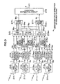
- an estimator of direction of desired signal 200 comprises first to Mth antennas 211 1 to 211 M , first to Mth reception RF units 212 1 to 212 M , first to 2Mth analog-to-digital converters (A/D:converters) 213 1 to 213 2M , first to M-1th complex conjugation circuits 214 1 to 214 M-1 , first to M-1th multipliers 215 1 to 215 M-1 , first and second adders 217 1 , 217 2 and a direction estimation circuit 216.
- A/D:converters analog-to-digital converters
- the first to Mth reception RF units 212 1 to 212 M orthogonal-detect the down-converted high-frequency reception signals and convert the high-frequency reception signals into first to Mth inphase component signals I 1 to I M and first to Mth quadrature component signals Q 1 to Q M of the baseband band, respectively.
- the first to 2Mth A/D converters 213 1 to 213 2M are adapted to convert the analog first to Mth inphase component signals I 1 to I M and the analog first to Mth quadrature component signals Q 1 to Q H into first to Mth digital inphase component signals DI 1 to DI M and first to Mth digital quadrature component signals DQ 1 to DQ M , respectively.
- the first and second A/D converters 213 1 , 213 2 are adapted to convert the analog first inphase component signal I 1 and the analog first quadrature component signal Q 1 outputted from the first reception unit 212 1 into the first digital inphase component signal DI 1 and the first digital quadrature component signal DQ 1 , respectively.
- the first complex conjugation circuit 214 1 calculates a complex conjugation of the second digital inphase component signal DI 2 and the second digital quadrature component signal DQ 2 by inverting a code of the second digital quadrature component signal DQ 2 outputted from the fourth A/D converter 213 4 , and then generates a first complex conjugation signal.
- the first multiplier 215 1 multiplies in vector the first digital inphase component signal DI 1 and the first digital quadrature component signal DQ 1 outputted from the first and second A/D converters 213 1 , 213 2 and the first complex conjugation signal outputted from the first complex conjugation circuit 214 1 .
- the first to M-1th multipliers 215 1 to 215 M-1 output first to M-1th real part signals M R1 to M R(M-1) and first to M-1th imaginary part signals M I1 to M I(M-1) of multiplied results M 1 to M M-1 in the first to Mth multipliers 215 1 to 215 M-1 , respectively.
- the first adder 217 1 is adapted to output a real part added signal M R by adding the first to Mth real part signals M R1 to M R(M-1) outputted from the first to M-1th multipliers 215 1 to 215 M-1 .
- the second adder 217 2 is adapted to output an imaginary part added signal M I by adding the first to M-1th imaginary part signals M I1 to M I(H-1) outputted from the first to M-1th multipliers 215 1 to 215 M-1 .
- the direction estimation circuit 216 is adapted to estimate the direction of the desired signal by using the real part added signal M R outputted from the first adder 217 1 and the imaginary part added signal M I outputted from the second adder 217 2 on the basis of the above-mentioned equation (3-2).
- the estimators 10, 200 according to the first and second embodiments estimate the direction of the desired signal by using one symbol of the known symbol series P (see Fig. 1) as described above, an estimation accuracy can be improved if there are used a plurality of symbols.
- the estimator 10 according to the first embodiment if the complex conjugation signal of the baseband signal of the output signal of one antenna and the baseband signal of the output signal of the other antenna are multiplied between the adjacent antennas, then the multiplied result does not become the function of the antenna number i as expressed by the above-mentioned equation (2-4) but becomes a function of a power of a reception symbol and a direction.
- the power of the equation (2-4) becomes equal during a different symbol time by using the known symbol series P in which the power of the reception symbol is equal, if the added value z shown in the equation (4-1) in which results respectively obtained with respect to N symbols are added is obtained, then it is possible to calculate the direction of the desired signal based on the equation (4-2): Although the signal power increases in response to the number of additions when the direction of the desired signal is calculated while the number of symbols is increased as described above, the power of Gaussian noises does not change even if they are added. Thus, it is possible to improve an S/N.
- An estimator of direction of desired signal 100 according to the third embodiment of the present invention is the above-mentioned estimator and is different from the estimator 10 of the first embodiment shown in Fig. 2 in that first and second symbol number accumulation units 118 1 , 118 2 are disposed between the multiplier 115 and the direction estimation circuit 116 as shown in Fig. 4.
- the complex conjugation circuit 114 and the multiplier 115 have the same functions as those of the first and second antennas 11 1 , 11 2 , the first and second reception RF units 12 1 , 12 2 , the first to fourth analog-to-digital converters (A/D converters) 13 1 to 13 4 , the complex conjugation circuit 14 and the multiplier 15 shown in Fig. 2, they need not be described herein but the first and second symbol number accumulation units 118 1 , 118 2 and the direction estimation circuit 116 will be described hereinafter.
- the first symbol number accumulation unit 118 1 is adapted to accumulate the real part signal M R outputted from the multiplier 115 by an amount of a predetermined symbol number N.
- the second symbol number accumulation unit 118 2 is adapted to accumulate the imaginary part signal M I outputted from the multiplier 115 by the amount of the predetermined symbol number N.
- the direction estimation circuit 116 is adapted to estimate the direction ⁇ of the desired signal based on the above-mentioned equations (4-1) and (4-2) by using an accumulated result Z R of the real part signal M R of the predetermined symbol number N and an accumulated result Z I of the imaginary part signal M I of the predetermined symbol number N outputted from the first and second symbol number accumulation units 118 1 , 118 2 .
- An estimator of direction of desired signal 300 according to the fourth embodiment of the present invention is a combination of the estimator 200 according to the second embodiment and the estimator 100 according to the third embodiment, and is able to improve an S/N by calculating the direction of the desired signal while the number of antennas and the number of symbols are increased.
- the added value z of powers and the direction ⁇ of the desired signal are expressed by the following equations:
- the estimator 300 according to this embodiment is different from the estimator 200 according to the second embodiment shown in Fig. 3 in that a first symbol number accumulation unit 318 1 is disposed between a first adder 317 1 and a direction estimation circuit 316 and a second symbol number accumulation unit 318 2 is disposed between a second adder 317 2 and the direction estimation circuit 316.
- first to Mth antennas 311 1 to 311 M , first to Mth reception RF units 312 1 to 312 M , first to 2Mth analog-to-digital converters (A/D converters) 313 1 to 313 2M , first to M-1th complex conjugation circuits 314 1 to 314 M-1 , first to M-1th multipliers 315 1 to 315 M-1 and first and second adders 317 1 , 317 2 have the same functions as those of the first to Mth antennas 211 1 to 211 M , the first to Mth reception RF units 212 1 to 212 M , the first to 2Mth analog-to-digital converters (A/D converters) 213 1 to 213 2M , the first to M-1th complex conjugation circuits 214 1 to 214 M-1 , the first to M-1th multipliers 215 1 to 215 M-1 and the first and second adders 217 1 , 217 2 shown in Fig. 3, they need not be described herein but the first
- the first symbol number accumulation unit 318 1 is adapted to accumulate the real part added signal M R outputted from the first adder 317 1 by the predetermined symbol number N.
- the second symbol number accumulation unit 318 2 is adapted to accumulate the imaginary part added signal M I outputted from the second adder 317 2 by the predetermined symbol number N.
- the direction estimation circuit 316 is adapted to estimate the direction ⁇ of the desired signal based on the above-mentioned equations (5-1) and (5-2) by using the accumulated result z R of the real part added signal M R of the predetermined symbol number N and the accumulated result z I of the imaginary part added signal M i of the predetermined symbol number N outputted from the first and second symbol number accumulation units 318 1 , 318 2 .
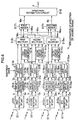
- An estimator of direction of desired signal 500 is used in a communication according to a CDMA (code division multiplex access) system.
- this estimator 500 comprises first to Mth antennas 511 1 to 511 M , first to Mth reception RF units 512 1 to 512 M , first to 2Mth analog-to-digital converters (A/D converters) 513 1 to 513 2M , first to 2Mth despread circuits 519 1 to 519 2M , first to M-1th complex conjugation circuits 514 1 to 514 M-1 , first to M-1th multipliers 515 1 to 515 M-1 , first and second adders 517 1 , 517 2 and a direction estimation circuit 516.
- A/D converters analog-to-digital converters
- the first to Mth reception RF units 512 1 to 512 M orthogonal-detect the down-converted high-frequency reception signals, and convert the high-frequency reception signals into first to Mth inphase component signals I 1 to I M and first to Mth quadrature component signals Q 1 to Q M of the baseband band, respectively.
- the first to 2Mth A/D converters 513 1 to 513 2M are adapted to convert analog first to Mth inphase component signals I 1 to I M and analog first to Mth quadrature component signals Q 1 to Q M outputted from the first to Mth reception RF units 512 1 to 512 M into first to Mth digital inphase component signals DI 1 to DI M and first to Mth digital quadrature component signals DQ 1 to DQ M , respectively.
- the first and second A/D converters 513 1 , 513 2 are adapted to convert the analog first inphase component signal I 1 and the analog first quadrature component signal Q 1 outputted from the first reception RF unit 512 1 into the first digital inphase component signal DI 1 and the first digital quadrature component signal DQ 1 , respectively.
- the first to 2Mth despread circuits 519 1 to 519 2M are adapted to despread the first to Mth digital inphase component signals DI 1 to DI M and the first to Mth digital quadrature component signals DQ 1 to DQ M outputted from the first to 2Mth A/D converters 513 1 to 513 2M , respectively.
- a reception signal s received at an ith antenna of array antennas which are linearly located at an equal interval with a half wavelength interval is expressed by the following equation if s 0 represents a transmission symbol and ⁇ represents an angle of a clockwise direction from the broad-side direction.
- the vector of the:direction remains in the result of the despread processing. Therefore, it is possible to estimate the direction of the desired signal by using the vector of the direction.
- the first complex conjugation circuit 514 1 calculates a complex conjugation of a despread processing result of the second digital inphase component signal DI 2 and a despread processing result of the second digital quadrature component signal DQ 2 by inverting the. code of the despread processing result of the second digital quadrature component signal DQ 2 outputted from the fourth despread circuit 519 4 , and generates the first complex conjugation signal.
- conjugation circuit 514 i see the above-mentioned equation (2-1)).
- the first multiplier 515 1 is adapted to multiply in vector the despread processing result of the first digital inphase component signal DI 1 and the despread result of the first digital quadrature component signal DQ 1 outputted from the first and second inverse diffusion circuits 219 1 , 219 2 and the first complex conjugation signal outputted from the first complex conjugation circuit 514 1 .
- the first to M-1th multipliers 515 1 to 515 M-1 are adapted to output first to M-1th real part signals M R1 to M R(M-1) and first to M-1th imaginary part signals M I1 to M I(M-1) of the multiplied results M 1 to M M-1 in the first to M-1th multipliers 515 1 to 515 M-1 , respectively.
- the first adder 517 1 adds the first to M-1th real part signals M R1 to M R(M-1) outputted from the first to M-1th multipliers 515 1 to 515 M-1 , and then outputs the real part added signal M R .
- the second adder 517 2 adds the first to M-1th imaginary part signals M I1 to M I(M-1) outputted from the first to M-1th multipliers 515 1 to 515 M-1 , and then outputs the imaginary part added signal M I .
- An added value z of powers and a direction ⁇ of the desired signal obtained where M assumes the number of antennas and N assumes the number of symbols are respectively expressed by the following equations:
- Re(•) represents the calculation of producing a real part, and its calculated result corresponds to the real part added signal M R .
- Im(•) represents the calculation of producing the imaginary part, and its calculated result corresponds to the imaginary part added signal M I .
- the direction estimation circuit 516 carries out the inverse tangent calculation and the inverse cosine calculation by using the real part added signal M R outputted from the first adder 517 1 and the imaginary part added signal M I outputted from the second adder 517 2 , and estimates the direction ⁇ of the desired signal based on the above-mentioned equation (6-6).
- the direction vector of the desired signal is calculated by effecting the complex conjugation calculation and the multiplication calculation on the despread symbol, that is, by effecting a similar calculation to the delayed detection calculation between the outputs of the adjacent antennas. Furthermore, by carrying out the addition of the combination of antennas in the adding circuit, it is possible to estimate the direction of the desired signal with the inverse tangent calculation and the inverse cosine calculation while the SN ratio also can be improved.
- the estimator since the calculation can be carried out not at the chip speed but at the symbol speed in the communication according to the CDMA system, it is possible to reduce the calculation speed to a 1/spread rate. Further, since the despread processing is carried out by using the same despread code as the spread code, with respect to an interference wave (interference signal) of the same direction as that of the desired wave, it is possible to reduce the electric power of the interference wave to a 1/process gain. As a consequence, it is possible to estimate the direction of the desired signal independently of the direction of the interference wave.
- the array antennas are located with the half wavelength interval as described above, so long as they are close to each other, they may be located with an interval of ⁇ /n.
- the second phase term of the above-mentioned equation (7-2) is expressed by e j2 ⁇ i/n•cos ⁇ .
- the multiplied results which are obtained by the above-mentioned equation (7-3) between the adjacent antennas may be added in case the modulation system in which the power of the transmission symbol becomes constant is used. Accordingly, if the direction of the desired signal is estimated by adding the multiplied results obtained by the above-mentioned equation (7-3) at every antenna and over all symbols, then it is possible to improve an SN ratio.
- An estimator of direction of desired signal 600 is the above-mentioned estimator.
- this estimator 600 includes first to Mth antennas 611 1 to 611 M , first to Mth reception RF units 612 1 to 612 M , first to 2Mth analog-to-digital converters (A/D converters) 613 1 to 613 2M , first to M-1th complex conjugation circuits 614 1 to 614 M-1 , first to M-1th multipliers 615 1 to 615 M-1 , first and second adders 617 1 , 617 2 , first and second symbol number accumulation units 618 1 , 618 2 and a direction estimation circuit 616.
- A/D converters analog-to-digital converters
- An operation of the estimator 600 according to this embodiment is similar to that of the estimator 300 according to the fourth embodiment shown in Fig. 5 but differs from that of the estimator 300 according to the fourth embodiment in the following points:
- the present invention is not limited thereto and the modulation system may be modulation systems other than the QPSK modulation system so long as the envelope of the transmission symbol becomes constant.
- the array antennas are located with the half wavelength interval as described above, so long as the array antennas are close to each other, they may be located with an interval of ⁇ /n.
- the second phase term of the above-mentioned equation (8-2) is expressed by e j2 ⁇ i/n•cos ⁇ .
- the multiplied result y i (n) does not become a function of the antenna number i, the phase ⁇ of the transmission symbol and the initial phase y of every start portion of slot no longer.
- multiplied results obtained by the above-mentioned equation (8-3) between the adjacent antennas may be added when the modulation system in which the power of the transmission symbol becomes constant is used. Therefore, if the direction of the desired signal is estimated by adding the multiplied results obtained in the above-mentioned equation (8-3) at every antenna and over all symbols, then it is possible to improve the SN ratio. Furthermore, if an average value of slots is calculated during a duration of time which can follow the change of direction of desired signal, then it is possible to improve the SN ratio much more.
- the estimator 700 according to the seventh embodiment of the present invention is the above-mentioned estimator. As shown in Fig. 9, the estimator 700 differs from the estimator 600 according to the sixth embodiment shown in Fig. 7 in that a first slot averaging circuit 720 1 is disposed between the first symbol number accumulation unit 718 1 and the direction estimation circuit 716 and a second slot averaging circuit 720 2 is disposed between the second symbol number accumulation circuit 718 2 and the direction estimation circuit 716.
- the first slot averaging circuit 720 1 averages the accumulated result of the real number added signal M R outputted from the first symbol number accumulation unit 718 1 .
- the second slot averaging circuit 720 2 averages the accumulated result of the imaginary part added signal M I outputted from the second symbol number accumulation unit 718 2 .
- An average length in the averaging processing in the first and second slot averaging circuits 720 1 , 720 2 should preferably be lower than a speed at which a direction of a desired signal is changed. Also, as a concrete method of the averaging processing, there are methods using a moving averaging and an oblivion coefficient, etc.
- the direction estimation circuit 716 is adapted to estimate the direction ⁇ of the desired signal based on the above-mentioned equations (8-1) to (8-3) by using the output signals from the first and second slot averaging circuits 720 1 , 720 2 .
- the present invention is not limited thereto and the modulation system may be other modulation systems than the QPSK modulation system so long as the envelope of the transmission symbol becomes constant.
- An estimator of direction of desired signal 700 according to the seventh embodiment could improve the SN ratio by updating the direction vector (corresponding to z in the above-mentioned equation (6-5) over a plurality of slots.
- the level of reception signal is fluctuated depending upon a propagation distance and a fading.
- a noise is added to the level of the reception signal at the reception RF unit of the receiver.
- the direction vector of the desired signal is not directed in the same direction so that, if the direction vector is added by the amount of one slot, then the added direction vector becomes smaller than that obtained in the case of a small noise.
- the estimator 800 calculates a power of a direction vector (corresponding to z in the above-mentioned equation (6-5)) of one slot period, compares the calculated power with a predetermined threshold value, and improves an SN ratio by updating the direction vector when the calculated power is larger than the predetermined threshold value.
- the estimator 800 differs from the estimator 700 according to the seventh embodiment shown in Fig. 9 in that it includes a power calculating circuit 821 to which output signals from first and second symbol number accumulation units 818 1 , 818 2 are inputted, a comparator 822 to which an output signal from the power calculating circuit 821 is inputted, a first switch 823 1 disposed between the first symbol number accumulation unit 818 1 and a first slot averaging circuit 820 1 and which is opened and closed in response to an output signal from the comparator 822 and a second switch 823 2 disposed between the second symbol number accumulation unit 818 2 and a second slot averaging circuit 820 2 and which is opened and closed in response to the output signal from the comparator 822.
- first to Mth antennas 811 1 to 811 M , first to Mth reception RF units 812 1 to 812 M , first to 2Mth analog-to-digital converters (A/D converters) 813 1 to 813 2M , first to M-1th complex conjugation circuits 814 1 to 814 M-1 , first to M-1th multipliers 815 1 to 815 M-1 , first and second adders 817 1 , 817 2 , the first and second symbol number accumulation units 818 1 , 818 2 , the first and second slot averaging circuit 820 1 , 820 2 and the direction estimation circuit 816 have the same functions as those of the first to Mth antennas 711 1 to 711 M , the first to Mth reception RF units 712 1 to 712 M , the first to 2Mth analog-to-digital converters (A/D converters) 713 1 to 713 2M , the first to M-1th complex conjugation circuits 714 1 to 714 M-1 , the first to Mth
- the power calculating circuit 821 is adapted to calculate a power of a direction vector of one slot period by using the output signals from the first and second symbol number accumulation units 818 1 , 818 2 .
- the comparator 822 compares the power of the direction vector of one slot period calculated by the power calculating circuit 821 with a predetermined threshold value, and closes the first and second switches 823 1 , 823 2 when the power of the direction vector of one slot period is larger than the predetermined threshold value. Therefore, when the power of the direction vector of one slot period is smaller than the threshold value, the output signals from the first and second symbol number accumulation units 818 1 , 818 2 are not inputted to the first and second slot averaging circuits 720 1 , 720 2 with the result that the direction vector is not updated.
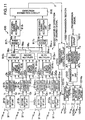
- a transmission and reception apparatus 400 which includes an estimation section of direction of desired signal 900 having a configuration similar to that of the estimator 300 according to the fourth embodiment shown in Fig. 5 and a transmission section 1000 for controlling a transmission direction of a transmission signal by using the direction ⁇ of the desired signal estimated by the estimation section 900 will next be described with reference to Fig. 11.
- the estimation unit 900 of the transmission and reception apparatus 400 includes first to Mth antennas 911 1 to 911 M , first to Mth reception RF units 912 1 to 912 M , first to 2Mth analog-to-digital converters (A/D converters) 913 1 to 913 2M , first to M-1th complex conjugation circuits 914 1 to 914 M-1 , first to M-1th multipliers 915 1 to 915 M-1 , first and second adders 917 1 , 917 2 , first and second symbol number accumulation units 918 1 , 918 2 and a direction estimation circuit 916.
- A/D converters analog-to-digital converters
- the transmission unit 1000 of the transmission and reception apparatus 400 includes a transmission directivity control circuit 1010, a mapping circuit 1011, first and second digital-to-analog converters (D/A converters) 1012 1 , 1012 2 , a transmission RF unit 1013, first to Mth phase shifters 1014 1 to 1014 M and first to Mth transmission antennas 1015 1 to 1015 M which configure array antennas.
- An operation of the estimation section 900 is similar to that of the above-mentioned estimator 300 according to the fourth embodiment, and therefore need not be described. But instead, an operation of the transmission section 1000 will be described hereinafter.
- a transmission signal T is mapped by the mapping circuit 1011 and thereby converted into an inphase component signal T I and a quadrature component signal T Q .
- the inphase component signal T I and the quadrature component signal T Q are converted by the first and second D/A converters 1012 1 , 1012 2 into an analog inphase component signal AT I and an analog quadrature component signal AT Q , respectively.
- the analog inphase component signal AT I and the analog quadrature component signal AT Q are converted by the transmission RF unit 1013 into a high-frequency transmission signal AT.
- the transmission directivity control circuit 1010 calculates the control signals of the first to Mth phase shifters 1014 1 to 1014 M by using the direction ⁇ of the desired signal estimated by the direction estimation circuit 916, and the calculated control signals are outputted to the first to Mth phase shifters 1014 1 to 1014 M .
- the high-frequency transmission signal AT is phase-controlled by the first to Mth phase shifters 1014 1 to 1014 M and then transmitted from the first to Mth transmission antennas 1015 1 to 1015 M , thereby controlling the radio waves transmitted from the first to Mth transmission antennas 1015 1 to 1015 M in such a manner that the phases of the radio waves are directed to the direction ⁇ of the desired signal.
- the transmission and reception apparatus 400 uses the estimation unit 900 having the configuration similar to that of the estimator 300 according to the fourth embodiment shown in Fig. 5 as described above, the present invention is not limited thereto, and the transmission and reception apparatus 400 may use an estimation unit having a configuration similar to that of the estimator 10 according to the first embodiment shown in Fig. 2, the estimator 200 according to the second embodiment shown in Fig. 3, the estimator 100 according to the third embodiment shown in Fig. 4, the estimator 500 according to the fifth embodiment shown in Fig. 6, the estimator 600 according to the sixth embodiment shown in Fig. 7, the estimator 700 according to the seventh embodiment shown in Fig. 9 or the estimator 800 according to the eighth embodiment shown in Fig. 10.
Landscapes
- Physics & Mathematics (AREA)
- Engineering & Computer Science (AREA)
- General Physics & Mathematics (AREA)
- Radar, Positioning & Navigation (AREA)
- Remote Sensing (AREA)
- Variable-Direction Aerials And Aerial Arrays (AREA)
- Monitoring And Testing Of Transmission In General (AREA)
- Noise Elimination (AREA)
- Mobile Radio Communication Systems (AREA)
- Radio Transmission System (AREA)
Claims (9)
- Estimateur désiré (10) pour estimer une direction d'un signal désiré caractérisé en ce qu'il est muni d'un réseau de M antennes (M > 1) disposées en une ou plusieurs paires de première et seconde antennes (111 à 11M, 2111 à 211M, 3111 à 311M, 5111 à 511M, 6111 à 611M, 7111 à 711M, 8111 à 811M, 9111 à 911M) pour recevoir ledit signal désiré ;
des premier et second circuits de conversion de signal (12 à 12M, 112 à 112M, 2121 à 212M, 3121 à 312M, 5121 à 512M, 6121 à 612M, 7121 à 712M, 8121 à 812M, 9121 à 912M), pour chaque antenne de chaque paire des antennes pour détection orthogonale des signaux de sortie desdites première et seconde antennes et pour convertir les signaux de sortie détectés en paires de premier et second signaux en bande de base (DI1 à DIM et DQ1 à DQM) ;
l'estimateur de direction (10) étant caractérisé en ce qu'il comprend de plus
M-1 circuits de conjugaison complexe (14, 114, 2141 à 214M, 3141 à 314M, 5141 à 514M-1, 6141 à 614M-1, 7141 à 714M-1, 8141 à 814M-1, 9141 à 914M), pour générer M-1 paires respectives des signaux de conjugaison complexe en calculant une conjugaison complexe des premier et second signaux en bande de base (DI2 à DIM et DQ2 à DQM) ou ;
M-1 multiplicateurs (15, 115, 215, 3151 à 315M-1, 5151 à 515M-1, 6151 à 615M-1, 7151 à 715M-1, 8151 à 815M-1, 9151 à 915M-1), pour multiplier les premier et second signaux en bande de base d'une première paire de signaux en bande de base avec respectivement un premier signal de conjugaison complexe et un second signal de conjugaison complexe d'une paire sélectionnée de conjugaisons ; et
un circuit d'estimation de direction (16) pour estimer la direction dudit signal désiré en effectuant un calcul de tangente inverse et un calcul de cosinus inverse sur le signal de sortie du multiplicateur ou de chaque multiplicateur. - Estimateur selon la revendication 1 comprenant en outre
des additionneurs (2171, 2172) pour additionner un signal de sortie du premier dit multiplicateur et un signal de sortie du second dit multiplicateur ; et
le circuit d'estimation de direction estime la direction dudit signal désiré en effectuant un calcul de tangente inverse et un calcul de cosinus inverse sur les signaux de sortie desdits additionneurs. - Estimateur selon la revendication 1 ou 2, pour estimer une direction d'un signal désiré contenant une pluralité de symboles connus ayant chacun une puissance égale comprenant en outre :une unité d'accumulation de nombre de symboles (1181, 1182) pour accumuler un signal de sortie dudit multiplicateur par rapport à au moins plus que deux symboles connus ; etle circuit d'estimation de direction (116) estime la direction dudit signal désiré en effectuant un calcul de tangente inverse et un calcul de cosinus inverse sur un signal de sortie de ladite unité d'accumulation de nombres de symboles.
- Estimateur (300) selon la revendication 3, dans lequel le premier multiplicateur (3151) est pour multiplier une première paire de signaux en bande de base correspondant auxdits symboles connus et une première paire de signaux de conjugaison complexe ;
le second multiplicateur (3152) est pour multiplier ladite seconde paire de signaux en bande de base correspondant auxdits symboles connus et ladite seconde paire de signaux de conjugaison complexe ;
comprenant de plus un additionneur (3171, 3172) pour additionner un signal de sortie dudit premier multiplicateur et un signal de sortie dudit second multiplicateur ;
une unité d'accumulation de nombres de symboles (3181, 3182) pour accumuler un signal de sortie dudit additionneur par rapport à au moins plus que deux symboles connus ; et
le circuit d'estimation de direction (316) estime la direction dudit signal désiré en effectuant un calcul de tangente inverse et un calcul de cosinus inverse sur un signal de sortie de ladite unité d'accumulation de nombres de symboles - Estimateur selon la revendication 4 comprenant, en outre, des circuits de désétalement (5191 à 5192M) pour désétaler lesdits signaux en bande de base,
lesdits premier et second circuits de conjugaison complexe (5141, 5142) sont mis en oeuvre pour générer des signaux de conjugaison complexe en calculant les conjugaisons complexes des signaux en bande de base désétalés sélectionnés,
le ou chaque premier multiplicateur (5151 à 515M-1) peut être mis en oeuvre pour multiplier les signaux en bande de base désétalés sélectionnés et pour sélectionner un ou plusieurs signaux de conjugaison ;
le, ou chaque second multiplicateur (5152) peut être mis en oeuvre pour multiplier les signaux en bande de base désétalés sélectionnés et le signal de conjugaison complexe sélectionné ;
l'additionneur (5171, 5172) peut être mis en oeuvre pour additionner un signal de sortie dudit premier multiplicateur et un signal de sortie dudit second multiplicateur ; et
le circuit d'estimation de direction (516) estime la direction dudit signal désiré en effectuant un calcul de tangente inverse et un calcul de cosinus inverse sur un signal de sortie dudit additionneur. - Estimateur (600) selon l'une quelconque des revendications 2 à 4 pour estimer une direction d'un signal désiré utilisée dans une communication en conformité avec un système de modulation dans lequel une enveloppe d'un symbole de transmission devient constante, ledit signal désiré contenant une pluralité de symboles connus et une pluralité de données, comprenant :des premier et second circuits de conjugaison complexe (6141, 6142) pouvant être mis en oeuvre pour générer des premier et second signaux de conjugaison complexe (D12 à D1M et DQ2 à DQM) en calculant les conjugaisons complexes des signaux en bande de base sélectionnés correspondant auxdits symboles connus et auxdites données ;le premier multiplicateur (6151) peut être mis en oeuvre pour multiplier des premier et second signaux en bande de base sélectionnés (D12 à D1M et DQ2 à DQM) d'une première paire de signaux en bande de base correspondant auxdits symboles connus et auxdites données et des premier et second signaux de conjugaison complexe sélectionnés d'une première paire de signaux de conjugaison ;le second multiplicateur (6152) peut être mis en oeuvre pour multiplier des premier et second signaux en bande de base sélectionnés (D12 à D1M et DQ2 à DQM) d'une première paire de signaux en bande de base correspondant auxdits symboles connus et auxdites données et des premier et second signaux de conjugaison complexe d'une seconde paire de signaux de conjugaison ;l'additionneur (6171, 6172) pouvant être mis en oeuvre pour additionner un signal de sortie dudit premier multiplicateur et un signal de sortie dudit second multiplicateur ;l'unité d'accumulation de nombres de symboles (6181, 6182) peut être mise en oeuvre pour accumuler un signal de sortie dudit additionneur par rapport à au moins plus que deux desdits symboles connus et à au moins plus que deux desdites données ; etle circuit d'estimation de direction (616) estime la direction dudit signal désiré en effectuant un calcul de tangente inverse et un calcul de cosinus inverse sur un signal de sortie de ladite unité d'accumulation de nombres de symboles.
- Estimateur (700) selon la revendication 6 pour estimer une direction d'un signal désiré utilisé dans une communication en conformité avec un système de modulation dans lequel une enveloppe d'un symbole de transmission devient constante, ledit signal désiré contenant une pluralité de symboles connus et une pluralité de données, comprenant en outre :un circuit de mise en moyenne de tranche (7201, 7202) pour mettre en moyenne un signal de sortie de ladite unité d'accumulation de nombres de symboles (7181, 7182) pendant une période d'au moins plus que deux tranches ; etle circuit d'estimation de direction (716) peut être mis en oeuvre pour estimer la direction dudit signal désiré en effectuant un calcul de tangente inverse et un calcul de cosinus inverse sur un signal de sortie dudit circuit de mise en moyenne de tranche.
- Estimateur selon la revendication 7, comprenant en outre :un circuit de calcul de puissance (821) pour calculer une puissance d'un vecteur de direction d'une tranche depuis le signal de sortie de ladite unité d'accumulation de nombres de symboles ; etun circuit de comparaison (822) pour comparer un signal de sortie dudit circuit de calcul de puissance et une valeur de seuil prédéterminée et pour entrer le signal de sortie de ladite unité d'accumulation de nombres de symboles dans ledit circuit de mise en moyenne de tranche lorsque le signal de sortie dudit circuit de calcul de puissance est plus grand que ladite valeur de seuil prédéterminée.
- Appareil d'émission et de réception (800) pour commander une direction d'émission d'un signal d'émission en utilisant une direction d'un signal désiré, comprenant :un estimateur selon l'une quelconque des revendications 1 à 8, dans lequel il est prévuun déphaseur (1014) pour commander la phase dudit signal d'émission ;un circuit de commande de directivité d'émission (1010) pour commander ledit déphaseur sur la base de la direction du signal désiré estimé par ledit estimateur et pour déterminer une phase dudit signal d'émission ; etune antenne d'émission (T) dans laquelle un signal de sortie dudit déphaseur est entrée.
Applications Claiming Priority (6)
| Application Number | Priority Date | Filing Date | Title |
|---|---|---|---|
| JP29757396 | 1996-10-20 | ||
| JP29757396 | 1996-10-20 | ||
| JP297573/96 | 1996-10-20 | ||
| JP02454197A JP3464879B2 (ja) | 1996-10-20 | 1997-01-24 | 到来方向推定装置 |
| JP24541/97 | 1997-01-24 | ||
| JP2454197 | 1997-01-24 |
Publications (3)
| Publication Number | Publication Date |
|---|---|
| EP0837340A2 EP0837340A2 (fr) | 1998-04-22 |
| EP0837340A3 EP0837340A3 (fr) | 1999-07-07 |
| EP0837340B1 true EP0837340B1 (fr) | 2005-03-16 |
Family
ID=26362083
Family Applications (1)
| Application Number | Title | Priority Date | Filing Date |
|---|---|---|---|
| EP97307909A Expired - Lifetime EP0837340B1 (fr) | 1996-10-20 | 1997-10-07 | Estimateur de direction de signal utile |
Country Status (6)
| Country | Link |
|---|---|
| US (1) | US5841400A (fr) |
| EP (1) | EP0837340B1 (fr) |
| JP (1) | JP3464879B2 (fr) |
| KR (1) | KR100273714B1 (fr) |
| CN (1) | CN1104780C (fr) |
| DE (1) | DE69732752T2 (fr) |
Families Citing this family (10)
| Publication number | Priority date | Publication date | Assignee | Title |
|---|---|---|---|---|
| US6600447B1 (en) * | 1997-12-19 | 2003-07-29 | Ericsson Inc. | Apparatus and method for determining signal direction from an estimated signal medium response for a ray component of a radio signal |
| GB2347571A (en) | 1999-03-03 | 2000-09-06 | Secr Defence | Locating system |
| JP4116624B2 (ja) * | 2003-03-11 | 2008-07-09 | 富士通株式会社 | 無線装置 |
| US7197336B2 (en) * | 2003-06-30 | 2007-03-27 | Intel Corporation | Method and apparatus to combine radio frequency signals |
| US7336739B2 (en) * | 2003-09-26 | 2008-02-26 | Lockheed Martin Corporation | Cross-correlation signal detector |
| JP2007078450A (ja) * | 2005-09-13 | 2007-03-29 | Mitsubishi Electric Corp | 方位探知装置 |
| CN101431354B (zh) * | 2007-11-09 | 2013-03-27 | 中兴通讯股份有限公司 | 一种波达角估计方法 |
| WO2011158056A1 (fr) * | 2010-06-19 | 2011-12-22 | Nokia Corporation | Procédé et appareil permettant d'estimer une direction d'arrivée |
| GB2484703A (en) * | 2010-10-21 | 2012-04-25 | Bluwireless Tech Ltd | Antenna array beam directing method and apparatus |
| CN108257238B (zh) * | 2018-02-13 | 2020-07-10 | 深圳市金溢科技股份有限公司 | 一种电子不停车收费设备及其射频前端和射频接收方法 |
Family Cites Families (3)
| Publication number | Priority date | Publication date | Assignee | Title |
|---|---|---|---|---|
| US4532515A (en) * | 1982-02-10 | 1985-07-30 | Cantrell Ben H | Angle of arrival measurements for two unresolved sources |
| EP0700116A3 (fr) * | 1994-08-29 | 1998-01-07 | Atr Optical And Radio Communications Research Laboratories | Appareil et procédé pour commander un réseau d'antennes avec une pluralité d'éléments d'antenne pour le poursuite améliorée du faisceau |
| US5572220A (en) * | 1995-05-18 | 1996-11-05 | Hughes Aircraft Company | Technique to detect angle of arrival with low ambiguity |
-
1997
- 1997-01-24 JP JP02454197A patent/JP3464879B2/ja not_active Expired - Fee Related
- 1997-10-07 EP EP97307909A patent/EP0837340B1/fr not_active Expired - Lifetime
- 1997-10-07 DE DE69732752T patent/DE69732752T2/de not_active Expired - Lifetime
- 1997-10-07 US US08/946,433 patent/US5841400A/en not_active Expired - Lifetime
- 1997-10-17 CN CN97120610A patent/CN1104780C/zh not_active Expired - Fee Related
- 1997-10-20 KR KR1019970053822A patent/KR100273714B1/ko not_active IP Right Cessation
Also Published As
| Publication number | Publication date |
|---|---|
| JP3464879B2 (ja) | 2003-11-10 |
| DE69732752T2 (de) | 2006-04-06 |
| EP0837340A3 (fr) | 1999-07-07 |
| CN1180963A (zh) | 1998-05-06 |
| EP0837340A2 (fr) | 1998-04-22 |
| CN1104780C (zh) | 2003-04-02 |
| KR19980032988A (ko) | 1998-07-25 |
| DE69732752D1 (de) | 2005-04-21 |
| US5841400A (en) | 1998-11-24 |
| JPH10177064A (ja) | 1998-06-30 |
| KR100273714B1 (ko) | 2001-01-15 |
Similar Documents
| Publication | Publication Date | Title |
|---|---|---|
| US7209512B2 (en) | CDMA receiver, and searcher in a CDMA receiver | |
| US6385181B1 (en) | Array antenna system of wireless base station | |
| US7031368B1 (en) | Adaptive transmitter/receiver | |
| EP0992813B1 (fr) | Dispositif d'antenne pour estimer la direction d' incidence d'un signal à fréquence radio | |
| US5585803A (en) | Apparatus and method for controlling array antenna comprising a plurality of antenna elements with improved incoming beam tracking | |
| US6243412B1 (en) | Adaptive array transmitter receiver | |
| EP1043801B1 (fr) | Système réseau d'antennes adaptatif | |
| US7453955B2 (en) | Receiving method and receiver | |
| US7010023B1 (en) | Path search circuit for simultaneously performing antenna directivity control and path search | |
| KR100664608B1 (ko) | 어레이 안테나를 이용한 무선 통신 장치 및 방법 | |
| CN100355220C (zh) | 阵列天线接收设备 | |
| KR100451278B1 (ko) | 적응성 안테나 수신장치 | |
| US7379513B2 (en) | Channel estimation in CDMA communications systems using both lower power pilot channel and higher power date channel | |
| EP0837340B1 (fr) | Estimateur de direction de signal utile | |
| CA2261841C (fr) | Dispositif de reception adaptatif pour antennes | |
| US7643587B2 (en) | Frequency offset estimating method and frequency offset correcting apparatus utilizing said method | |
| US7502431B2 (en) | Method and apparatus for estimating response characteristic, and receiving method and receiver utilizing the same | |
| AU722691B2 (en) | Radio communication apparatus and radio communication method | |
| US7116999B2 (en) | Mobile communications receiving apparatus and method | |
| US6317611B1 (en) | Communication device with adaptive antenna | |
| EP0984562B1 (fr) | Détection synchrone par interpolation de pilote dans un récepteur du type Rake | |
| EP1146665A1 (fr) | Dispositif de station de base et procede de reception radio | |
| KR20000076706A (ko) | 라그랑제 다항식 보간법을 이용한 채널 왜곡의 보상 방법및 시스템 | |
| JP3017400B2 (ja) | アレーアンテナの制御方法及び制御装置 | |
| JP7289600B2 (ja) | 無線受信装置 |
Legal Events
| Date | Code | Title | Description |
|---|---|---|---|
| PUAI | Public reference made under article 153(3) epc to a published international application that has entered the european phase |
Free format text: ORIGINAL CODE: 0009012 |
|
| 17P | Request for examination filed |
Effective date: 19971017 |
|
| AK | Designated contracting states |
Kind code of ref document: A2 Designated state(s): DE FI FR GB SE |
|
| PUAL | Search report despatched |
Free format text: ORIGINAL CODE: 0009013 |
|
| RIC1 | Information provided on ipc code assigned before grant |
Free format text: 6G 01S 3/74 A, 6G 01S 3/14 B, 6G 01S 3/48 B, 6G 01S 3/04 B, 6H 01Q 3/26 B |
|
| AK | Designated contracting states |
Kind code of ref document: A3 Designated state(s): AT BE CH DE DK ES FI FR GB GR IE IT LI LU MC NL PT SE |
|
| AKX | Designation fees paid |
Free format text: DE FI FR GB SE |
|
| 17Q | First examination report despatched |
Effective date: 20030207 |
|
| GRAP | Despatch of communication of intention to grant a patent |
Free format text: ORIGINAL CODE: EPIDOSNIGR1 |
|
| GRAS | Grant fee paid |
Free format text: ORIGINAL CODE: EPIDOSNIGR3 |
|
| GRAA | (expected) grant |
Free format text: ORIGINAL CODE: 0009210 |
|
| AK | Designated contracting states |
Kind code of ref document: B1 Designated state(s): DE FI FR GB SE |
|
| REG | Reference to a national code |
Ref country code: GB Ref legal event code: FG4D |
|
| REF | Corresponds to: |
Ref document number: 69732752 Country of ref document: DE Date of ref document: 20050421 Kind code of ref document: P |
|
| REG | Reference to a national code |
Ref country code: SE Ref legal event code: TRGR |
|
| ET | Fr: translation filed | ||
| PLBE | No opposition filed within time limit |
Free format text: ORIGINAL CODE: 0009261 |
|
| STAA | Information on the status of an ep patent application or granted ep patent |
Free format text: STATUS: NO OPPOSITION FILED WITHIN TIME LIMIT |
|
| 26N | No opposition filed |
Effective date: 20051219 |
|
| PGFP | Annual fee paid to national office [announced via postgrant information from national office to epo] |
Ref country code: DE Payment date: 20100929 Year of fee payment: 14 |
|
| PGFP | Annual fee paid to national office [announced via postgrant information from national office to epo] |
Ref country code: GB Payment date: 20101006 Year of fee payment: 14 |
|
| PGFP | Annual fee paid to national office [announced via postgrant information from national office to epo] |
Ref country code: SE Payment date: 20111011 Year of fee payment: 15 Ref country code: FR Payment date: 20111103 Year of fee payment: 15 Ref country code: FI Payment date: 20111011 Year of fee payment: 15 |
|
| GBPC | Gb: european patent ceased through non-payment of renewal fee |
Effective date: 20121007 |
|
| REG | Reference to a national code |
Ref country code: FR Ref legal event code: ST Effective date: 20130628 |
|
| PG25 | Lapsed in a contracting state [announced via postgrant information from national office to epo] |
Ref country code: SE Free format text: LAPSE BECAUSE OF NON-PAYMENT OF DUE FEES Effective date: 20121008 Ref country code: DE Free format text: LAPSE BECAUSE OF NON-PAYMENT OF DUE FEES Effective date: 20130501 Ref country code: GB Free format text: LAPSE BECAUSE OF NON-PAYMENT OF DUE FEES Effective date: 20121007 |
|
| REG | Reference to a national code |
Ref country code: DE Ref legal event code: R119 Ref document number: 69732752 Country of ref document: DE Effective date: 20130501 |
|
| PG25 | Lapsed in a contracting state [announced via postgrant information from national office to epo] |
Ref country code: FR Free format text: LAPSE BECAUSE OF NON-PAYMENT OF DUE FEES Effective date: 20121031 Ref country code: FI Free format text: LAPSE BECAUSE OF NON-PAYMENT OF DUE FEES Effective date: 20121007 |