EP0836033A2 - Support pour une unité motrice vibratoire - Google Patents
Support pour une unité motrice vibratoire Download PDFInfo
- Publication number
- EP0836033A2 EP0836033A2 EP97114534A EP97114534A EP0836033A2 EP 0836033 A2 EP0836033 A2 EP 0836033A2 EP 97114534 A EP97114534 A EP 97114534A EP 97114534 A EP97114534 A EP 97114534A EP 0836033 A2 EP0836033 A2 EP 0836033A2
- Authority
- EP
- European Patent Office
- Prior art keywords
- bearing
- connection
- current conductor
- bearing according
- support body
- Prior art date
- Legal status (The legal status is an assumption and is not a legal conclusion. Google has not performed a legal analysis and makes no representation as to the accuracy of the status listed.)
- Granted
Links
Images


Classifications
-
- F—MECHANICAL ENGINEERING; LIGHTING; HEATING; WEAPONS; BLASTING
- F16—ENGINEERING ELEMENTS AND UNITS; GENERAL MEASURES FOR PRODUCING AND MAINTAINING EFFECTIVE FUNCTIONING OF MACHINES OR INSTALLATIONS; THERMAL INSULATION IN GENERAL
- F16F—SPRINGS; SHOCK-ABSORBERS; MEANS FOR DAMPING VIBRATION
- F16F13/00—Units comprising springs of the non-fluid type as well as vibration-dampers, shock-absorbers, or fluid springs
- F16F13/04—Units comprising springs of the non-fluid type as well as vibration-dampers, shock-absorbers, or fluid springs comprising both a plastics spring and a damper, e.g. a friction damper
- F16F13/06—Units comprising springs of the non-fluid type as well as vibration-dampers, shock-absorbers, or fluid springs comprising both a plastics spring and a damper, e.g. a friction damper the damper being a fluid damper, e.g. the plastics spring not forming a part of the wall of the fluid chamber of the damper
- F16F13/08—Units comprising springs of the non-fluid type as well as vibration-dampers, shock-absorbers, or fluid springs comprising both a plastics spring and a damper, e.g. a friction damper the damper being a fluid damper, e.g. the plastics spring not forming a part of the wall of the fluid chamber of the damper the plastics spring forming at least a part of the wall of the fluid chamber of the damper
- F16F13/10—Units comprising springs of the non-fluid type as well as vibration-dampers, shock-absorbers, or fluid springs comprising both a plastics spring and a damper, e.g. a friction damper the damper being a fluid damper, e.g. the plastics spring not forming a part of the wall of the fluid chamber of the damper the plastics spring forming at least a part of the wall of the fluid chamber of the damper the wall being at least in part formed by a flexible membrane or the like
Definitions
- the invention relates to a bearing for supporting an oscillatory unit, in particular an engine and / or a transmission of a motor vehicle, according to the preamble of claim 1.
- the known bearings only serve to store an assembly.
- To close of an electrical circuit, for example in a motor vehicle required that an earth cable be connected to the body of an engine is.
- an earth cable be connected to the body of an engine is.
- the use of a separate earth cable requires additional ones Costs in terms of logistics and assembly, since a screw connection of the Earth cables on the engine and body side must be done.
- the object of the invention is a bearing for supporting a vibratable To create aggregates that reduce assembly costs.
- the bearing according to the invention advantageously combines the storage functions and electrical conductivity.
- the bearing according to the invention consists of at least one electrically conductive connection to an aggregate, the Vibrations should be damped.
- a component used for damping either directly or via at least an additional component connected to at least one electrically conductive connection is, this connection to a the bearing and thus the unit load-bearing component and the vibrations of the unit is.
- the electrical connection between the unit-side connection and the Connection to the support component can advantageously by separate power lines or the like and / or by conductive integrated in the damping component Funds.
- this is not or not sufficiently conductive Damping component, which is usually made of rubber or an elastomer, made electrically conductive by adding conductive substances.
- a hydraulic bearing which in addition to the elastomeric damping component in one Cavity has a fluid, in particular a hydraulic fluid, it is from Advantage if this fluid is electrically mixed with conductive substances becomes conductive.
- At least one current conductor such as a conductive rope or a tape or a wire or a conductive braid or fabric in the Arrange bearings so that the two electrically separate connections are electrically connected to one another by the measures mentioned.
- the current conductors mentioned can advantageously on the outer surface or be arranged within the camp. There is an integrated one inside the warehouse Arrangement of the current conductors in the fixed damping component possible.
- In another advantageous embodiment can in particular in a hydraulic bearing Current conductor at least partially on the inner surface of the fixed damping component or run adjacent to it.
- the electrical current conductors have a sufficient elasticity or length to accommodate the movements to be able to participate in the bearing in a non-destructive manner under the influence of vibrations.
- the current conductor consists of a rope and / or a ribbon and / or a fabric and / or a braid.
- This Conductor is on the outer surface of the bearing with a closed cross section arranged or wrapped around the bearing so that this conductor also serves as a stop or limit.
- the current conductor is a capsule or Cap formed, the at least one substantially U-shaped cross section having.
- This current conductor is used by appropriate selection of a suitable one Materials also as thermal protection. Depending on the application, prevented this conductive heat protection cap a heat flow in the camp or the heat protection cap serves as a surface enlargement, so that the resulting in the warehouse Heat can flow out more easily.
- FIG. 1 shows a bearing 1, which is designed as a hydraulic bearing.
- the camp 1 points a threaded connection 2, which consists of a conductive Material such as B. steel.
- the connection 2 is fastened to a bearing core 3, the same or a different conductive material as the bolt-shaped Connection 2 exists.
- At the connection 2 is an aggregate, for example a motor, not shown, attached.
- a support body 4 is provided with the bearing core 3 connected, which is made of a damping material such as rubber or an elastomer.
- the support body 4 is made of a housing 5 arranged a conductive material. Is on a bottom side 36 of the housing 5 a further connection 7 is formed from a conductive material.
- an interior 12 filled with a hydraulic fluid 11 is formed between one Inner surface 8 of the supporting body 4 and a closing part provided with openings 9 10.
- an interior 12 filled with a hydraulic fluid 11 is formed between one Inner surface 8 of the supporting body 4 and a closing part provided with openings 9 10.
- the hydraulic fluid 11 in a below of the end part 10 trained compensation space 13 flow through a Diaphragm or a bellows 14 is limited.
- the damping component 6 in a hydraulic bearing consists of the support body 4 and the hydraulic fluid located in the cavity or interior 12.
- a conductive substance 16 mixed through which the support body 4 is electrically conductive.
- This conductive Substance 16 can be, for example, a powder and / or grains and / or Chips or the like.
- a line 17 provided with arrows is a The current flow is shown symbolically, with the electrical current in connection 2 flows in and over the bearing core 3, the support body 4, the housing 5 in the Port 7 and flows out of this.
- FIG. 2 shows a bearing 18 which is also designed as a hydraulic bearing and which is the same Components such as the bearing 1 of Figure 1. These components point accordingly the same reference numerals.
- the hydraulic fluid 11 located in the interior 12 by the addition of a suitable liquid or powdery substance 19 electrically conductive.
- the current path is symbolically identified by a line 17 provided with arrows, wherein the current now flows through the hydraulic fluid 11.
- FIG. 3 shows a bearing 20 designed as a hydraulic bearing, which essentially corresponds to the bearing 1 and in which the same components with the same Reference numerals are provided.
- a current conductor 21 in the form of a rope and / or ribbon and / or wire integrated.
- another current conductor 22 is arranged, which consists of a fabric and / or a Braid exists.
- the current conductor 22 is either directly on the inner surface 8 of the Support body 4 and / or spaced apart according to the existing Stretchability arranged, as shown in dashed lines in Figure 3 is.
- a current both overflows the current conductor 21 and the current conductor 22.
- the current paths 23 and 24 are symbolized by lines with arrows.
- FIG. 4 shows a bearing 25 which is designed as a hydraulic bearing.
- the camp 25 has the same components as the bearing 1, correspondingly with the same Reference numerals are provided.
- a current conductor is on the bearing core 3 of the bearing 25 26 connected at one end 27, the other end 28 of the Current conductor 26 is conductively attached to the housing 5.
- the current conductor 26 can be connected to connection 2 and / or connection 7 be connected.
- the length of the conductor 26 is dimensioned so that the Current conductor 26 the movements of the bearing 25 occurring during operation without destruction can participate.
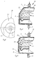
- Figures 5 and 6 show a bearing 29 which is designed as a hydraulic bearing.
- the bearing 29 has the same components as the bearing 1, which accordingly are provided with the same reference numerals.
- 29 is on the bearing Current conductor 30 is provided, which has a closed cross section. Of the Current conductor 30 also serves as a path limitation or stop.
- the current conductor 30 is designed in the form of a strip. In other embodiments A plurality of current conductors 30 can be provided. The number of Current conductor 30 and the dimensions of the respective current conductor 30 are by the occurring forces, movements and currents determined.
- FIG. 7 shows a bearing 32 which is designed as a hydraulic bearing and essentially consists of the same components as the bearing 1.
- the same components are correspondingly provided with the same reference numerals as for bearing 1.
- the bearing 32 surrounds a cap 33 made of an electrically conductive material the outer surface 34 of the bearing 32.
- the material of the cap 33 has at the same time a heat-insulating effect, so that the cap 33 additionally as Protection against heat acting on the outside of the bearing 32 is used.
- the electrically conductive material of the cap 33 is so designed that the cap 33 serves to enlarge the surface, so that the Bearing 32 generated heat can be better released to the environment.
- the Cap 33 of the embodiment shown in Figure 7 essentially covers the External surfaces of the connection 2 and the support body 4 as well as the peripheral surface 36 of the housing 5.
Landscapes
- Engineering & Computer Science (AREA)
- General Engineering & Computer Science (AREA)
- Mechanical Engineering (AREA)
- Support Of The Bearing (AREA)
- Mounting Of Bearings Or Others (AREA)
- Bridges Or Land Bridges (AREA)
Applications Claiming Priority (2)
| Application Number | Priority Date | Filing Date | Title |
|---|---|---|---|
| DE19641938 | 1996-10-11 | ||
| DE19641938A DE19641938A1 (de) | 1996-10-11 | 1996-10-11 | Lager zur Abstützung eines schwingungsfähigen Aggregates |
Publications (3)
| Publication Number | Publication Date |
|---|---|
| EP0836033A2 true EP0836033A2 (fr) | 1998-04-15 |
| EP0836033A3 EP0836033A3 (fr) | 1998-12-09 |
| EP0836033B1 EP0836033B1 (fr) | 2003-11-19 |
Family
ID=7808457
Family Applications (1)
| Application Number | Title | Priority Date | Filing Date |
|---|---|---|---|
| EP97114534A Expired - Lifetime EP0836033B1 (fr) | 1996-10-11 | 1997-08-22 | Support pour une unité motrice vibratoire |
Country Status (2)
| Country | Link |
|---|---|
| EP (1) | EP0836033B1 (fr) |
| DE (2) | DE19641938A1 (fr) |
Cited By (1)
| Publication number | Priority date | Publication date | Assignee | Title |
|---|---|---|---|---|
| EP1031759A1 (fr) * | 1999-02-24 | 2000-08-30 | Firma Carl Freudenberg | Support commutable à amortissement hydraulique |
Families Citing this family (8)
| Publication number | Priority date | Publication date | Assignee | Title |
|---|---|---|---|---|
| DE20105733U1 (de) | 2001-04-02 | 2001-10-11 | TRW Automotive Safety Systems GmbH & Co. KG, 63743 Aschaffenburg | Schwingungsentkoppelt gelagerter Gasgenerator |
| DE102008000854B4 (de) | 2008-03-27 | 2011-12-22 | Zf Friedrichshafen Ag | Kugelgelenk, Spurstange und Lenkvorrichtung |
| DE102009036856A1 (de) * | 2009-08-10 | 2011-02-17 | Magna Steyr Fahrzeugtechnik Ag & Co. Kg | Elektrische Maschine mit vor Stromdurchschlägen geschütztem Wälzlager und Getriebemotor mit einem solchen |
| DE102016225470B4 (de) * | 2016-12-19 | 2022-11-03 | Volkswagen Aktiengesellschaft | Aggregatlager zum Abstützen einer Antriebskomponente eines Kraftfahrzeuges |
| DE102017207662B4 (de) * | 2017-05-08 | 2020-10-01 | Audi Ag | Aggregatelager für ein Kraftfahrzeug, Antriebseinrichtung für ein Kraftfahrzeug sowie Kraftfahrzeug |
| DE102019105865A1 (de) * | 2019-03-07 | 2020-09-10 | Bayerische Motoren Werke Aktiengesellschaft | Achsträger eines Fahrzeugs mit einer elektrischen Komponente |
| DE102019110331A1 (de) * | 2019-04-18 | 2020-10-22 | Bayerische Motoren Werke Aktiengesellschaft | Elastisches Lager für eine Fahrzeug-Komponente |
| DE102022131590A1 (de) * | 2022-11-29 | 2024-05-29 | Bayerische Motoren Werke Aktiengesellschaft | Anordnung für ein zumindest teilweise elektrisch betriebenes Kraftfahrzeug, sowie Kraftfahrzeug |
Family Cites Families (9)
| Publication number | Priority date | Publication date | Assignee | Title |
|---|---|---|---|---|
| DE2332791C3 (de) * | 1973-06-28 | 1984-09-13 | Stabilus Gmbh, 5400 Koblenz | Gasfeder |
| FR2255508B1 (fr) * | 1973-12-21 | 1976-10-08 | Vibrachoc Sa | |
| FR2340834A1 (fr) * | 1976-02-16 | 1977-09-09 | Renault | Suspension pour bloc-moteurs |
| EP0187188A3 (fr) * | 1984-12-08 | 1988-09-28 | Audi Ag | Limiteur d'extension |
| FR2622660B1 (fr) * | 1987-10-28 | 1991-08-02 | Caoutchouc Manuf Plastique | Cale elastique a rigidite bloquee dans une direction par la tension d'un cable noye dans l'elastomere |
| DE3833182A1 (de) * | 1988-09-30 | 1990-04-05 | Freudenberg Carl Fa | Gummilager |
| JPH06129462A (ja) * | 1992-10-13 | 1994-05-10 | Bridgestone Corp | 防振装置 |
| FR2704612B1 (fr) * | 1993-04-28 | 1995-07-07 | Hutchinson | Support antivibratoire à dispositif de limitation des débattements en extension. |
| DE69622141T2 (de) * | 1996-01-11 | 2002-11-28 | Ford France S.A., Rueil-Malmaison | Magnetorheologisches Elastomer benutzende Buchse mit veränderlicher Steifigkeit |
-
1996
- 1996-10-11 DE DE19641938A patent/DE19641938A1/de not_active Withdrawn
-
1997
- 1997-08-22 EP EP97114534A patent/EP0836033B1/fr not_active Expired - Lifetime
- 1997-08-22 DE DE59711027T patent/DE59711027D1/de not_active Expired - Lifetime
Cited By (1)
| Publication number | Priority date | Publication date | Assignee | Title |
|---|---|---|---|---|
| EP1031759A1 (fr) * | 1999-02-24 | 2000-08-30 | Firma Carl Freudenberg | Support commutable à amortissement hydraulique |
Also Published As
| Publication number | Publication date |
|---|---|
| EP0836033A3 (fr) | 1998-12-09 |
| EP0836033B1 (fr) | 2003-11-19 |
| DE59711027D1 (de) | 2003-12-24 |
| DE19641938A1 (de) | 1998-04-16 |
Similar Documents
| Publication | Publication Date | Title |
|---|---|---|
| DE69512009T2 (de) | Elektrorheologische Flüssigkeit benutzender Schwingungsdämpfer | |
| EP0107675B1 (fr) | Connecteur electrique | |
| DE69505165T2 (de) | Elektrischer Kabelendverschluss | |
| EP1999831B1 (fr) | Accouplement des barres collectrices | |
| EP0836033A2 (fr) | Support pour une unité motrice vibratoire | |
| DE2934805C2 (de) | Elektrische Hochspannungsdurchführung | |
| DE3405315C2 (fr) | ||
| EP0847062B1 (fr) | Limiteur de surtension | |
| DE4320906C2 (de) | Gehäuse für einen druckgasisolierten Hochspannungs- Leistungs-Schalter | |
| DE102008000854B4 (de) | Kugelgelenk, Spurstange und Lenkvorrichtung | |
| DE3137783C2 (de) | Gasisolierte Dreiphasen-Sammelschiene | |
| EP0175637B1 (fr) | Connexion conductrice de courant à vis entre conducteurs tubulaires d'une installation électrique, en particulier d'une installation haute tension à blindage métallique | |
| EP0134525B1 (fr) | Traversée électrique à haute tension pour un appareil électrique enfermé dans un boîtier | |
| EP2243204A1 (fr) | Dispositif de contenants sous pression | |
| DE2733815A1 (de) | Sperr- oder uebergangsmuffe fuer hochspannungskabel | |
| EP3348764B1 (fr) | Dispositif d'actionnement au moins partiellement automatique d'un vantail de porte | |
| DE2939600A1 (de) | Steckbare verbindungsmuffe | |
| EP3093938B1 (fr) | Système d'exécution haute tension | |
| DE10010728C1 (de) | Kapselungsbaustein für eine dreiphasige Sammelschiene einer Hochspannungsanlage | |
| DE10305169B4 (de) | Anordnung mit einer Vakuumschaltröhre | |
| DE69210131T2 (de) | Anordnung zum Verbinden zweier Kabel für hohe oder sehr hohe Spannung | |
| DE20118493U1 (de) | Schaltkontaktanordnung für einen elektrischen Schalter | |
| DE19727855C1 (de) | Gasisolierte Schaltanlage | |
| DE102020200329A1 (de) | Feldabstandhalter | |
| DE19635366A1 (de) | Bewegbare Kontaktanordnung für einen Niederspannungs-Leistungsschalter mit einem Schwenklager |
Legal Events
| Date | Code | Title | Description |
|---|---|---|---|
| PUAI | Public reference made under article 153(3) epc to a published international application that has entered the european phase |
Free format text: ORIGINAL CODE: 0009012 |
|
| AK | Designated contracting states |
Kind code of ref document: A2 Designated state(s): DE FR GB |
|
| AX | Request for extension of the european patent |
Free format text: AL;LT;LV;RO;SI |
|
| PUAL | Search report despatched |
Free format text: ORIGINAL CODE: 0009013 |
|
| AK | Designated contracting states |
Kind code of ref document: A3 Designated state(s): AT BE CH DE DK ES FI FR GB GR IE IT LI LU MC NL PT SE |
|
| AX | Request for extension of the european patent |
Free format text: AL;LT;LV;RO;SI |
|
| RHK1 | Main classification (correction) |
Ipc: F16F 13/08 |
|
| 17P | Request for examination filed |
Effective date: 19981221 |
|
| AKX | Designation fees paid |
Free format text: DE FR GB |
|
| 17Q | First examination report despatched |
Effective date: 20020515 |
|
| GRAH | Despatch of communication of intention to grant a patent |
Free format text: ORIGINAL CODE: EPIDOS IGRA |
|
| GRAS | Grant fee paid |
Free format text: ORIGINAL CODE: EPIDOSNIGR3 |
|
| GRAA | (expected) grant |
Free format text: ORIGINAL CODE: 0009210 |
|
| AK | Designated contracting states |
Kind code of ref document: B1 Designated state(s): DE FR GB |
|
| REG | Reference to a national code |
Ref country code: GB Ref legal event code: FG4D Free format text: NOT ENGLISH |
|
| GBT | Gb: translation of ep patent filed (gb section 77(6)(a)/1977) |
Effective date: 20031119 |
|
| REF | Corresponds to: |
Ref document number: 59711027 Country of ref document: DE Date of ref document: 20031224 Kind code of ref document: P |
|
| ET | Fr: translation filed | ||
| PLBE | No opposition filed within time limit |
Free format text: ORIGINAL CODE: 0009261 |
|
| STAA | Information on the status of an ep patent application or granted ep patent |
Free format text: STATUS: NO OPPOSITION FILED WITHIN TIME LIMIT |
|
| 26N | No opposition filed |
Effective date: 20040820 |
|
| PGFP | Annual fee paid to national office [announced via postgrant information from national office to epo] |
Ref country code: DE Payment date: 20140906 Year of fee payment: 18 |
|
| PGFP | Annual fee paid to national office [announced via postgrant information from national office to epo] |
Ref country code: GB Payment date: 20140828 Year of fee payment: 18 Ref country code: FR Payment date: 20140828 Year of fee payment: 18 |
|
| REG | Reference to a national code |
Ref country code: DE Ref legal event code: R119 Ref document number: 59711027 Country of ref document: DE |
|
| GBPC | Gb: european patent ceased through non-payment of renewal fee |
Effective date: 20150822 |
|
| REG | Reference to a national code |
Ref country code: FR Ref legal event code: ST Effective date: 20160429 |
|
| PG25 | Lapsed in a contracting state [announced via postgrant information from national office to epo] |
Ref country code: DE Free format text: LAPSE BECAUSE OF NON-PAYMENT OF DUE FEES Effective date: 20160301 Ref country code: GB Free format text: LAPSE BECAUSE OF NON-PAYMENT OF DUE FEES Effective date: 20150822 |
|
| PG25 | Lapsed in a contracting state [announced via postgrant information from national office to epo] |
Ref country code: FR Free format text: LAPSE BECAUSE OF NON-PAYMENT OF DUE FEES Effective date: 20150831 |