EP0834026B1 - Frein a disque - Google Patents
Frein a disque Download PDFInfo
- Publication number
- EP0834026B1 EP0834026B1 EP96918771A EP96918771A EP0834026B1 EP 0834026 B1 EP0834026 B1 EP 0834026B1 EP 96918771 A EP96918771 A EP 96918771A EP 96918771 A EP96918771 A EP 96918771A EP 0834026 B1 EP0834026 B1 EP 0834026B1
- Authority
- EP
- European Patent Office
- Prior art keywords
- force
- shaft
- disc brake
- return
- transmission device
- Prior art date
- Legal status (The legal status is an assumption and is not a legal conclusion. Google has not performed a legal analysis and makes no representation as to the accuracy of the status listed.)
- Expired - Lifetime
Links
- 230000005540 biological transmission Effects 0.000 claims abstract description 14
- 230000015572 biosynthetic process Effects 0.000 claims description 10
- 238000005755 formation reaction Methods 0.000 claims description 10
- 230000003019 stabilising effect Effects 0.000 claims description 2
- 238000000926 separation method Methods 0.000 claims 1
- 230000014759 maintenance of location Effects 0.000 abstract 1
- 230000000712 assembly Effects 0.000 description 10
- 238000000429 assembly Methods 0.000 description 10
- 230000007246 mechanism Effects 0.000 description 9
- 230000008901 benefit Effects 0.000 description 3
- 239000000463 material Substances 0.000 description 3
- 230000001681 protective effect Effects 0.000 description 3
- 230000000295 complement effect Effects 0.000 description 2
- 239000002184 metal Substances 0.000 description 2
- 238000000034 method Methods 0.000 description 2
- 230000002093 peripheral effect Effects 0.000 description 2
- 229920003023 plastic Polymers 0.000 description 2
- 239000004033 plastic Substances 0.000 description 2
- 230000009471 action Effects 0.000 description 1
- 238000004873 anchoring Methods 0.000 description 1
- 230000006835 compression Effects 0.000 description 1
- 238000007906 compression Methods 0.000 description 1
- 230000000694 effects Effects 0.000 description 1
- 230000004048 modification Effects 0.000 description 1
- 238000012986 modification Methods 0.000 description 1
- 230000008439 repair process Effects 0.000 description 1
- 230000000717 retained effect Effects 0.000 description 1
- 125000006850 spacer group Chemical group 0.000 description 1
Images

Classifications
-
- F—MECHANICAL ENGINEERING; LIGHTING; HEATING; WEAPONS; BLASTING
- F16—ENGINEERING ELEMENTS AND UNITS; GENERAL MEASURES FOR PRODUCING AND MAINTAINING EFFECTIVE FUNCTIONING OF MACHINES OR INSTALLATIONS; THERMAL INSULATION IN GENERAL
- F16D—COUPLINGS FOR TRANSMITTING ROTATION; CLUTCHES; BRAKES
- F16D65/00—Parts or details
- F16D65/14—Actuating mechanisms for brakes; Means for initiating operation at a predetermined position
- F16D65/16—Actuating mechanisms for brakes; Means for initiating operation at a predetermined position arranged in or on the brake
- F16D65/18—Actuating mechanisms for brakes; Means for initiating operation at a predetermined position arranged in or on the brake adapted for drawing members together, e.g. for disc brakes
- F16D65/183—Actuating mechanisms for brakes; Means for initiating operation at a predetermined position arranged in or on the brake adapted for drawing members together, e.g. for disc brakes with force-transmitting members arranged side by side acting on a spot type force-applying member
-
- F—MECHANICAL ENGINEERING; LIGHTING; HEATING; WEAPONS; BLASTING
- F16—ENGINEERING ELEMENTS AND UNITS; GENERAL MEASURES FOR PRODUCING AND MAINTAINING EFFECTIVE FUNCTIONING OF MACHINES OR INSTALLATIONS; THERMAL INSULATION IN GENERAL
- F16D—COUPLINGS FOR TRANSMITTING ROTATION; CLUTCHES; BRAKES
- F16D65/00—Parts or details
- F16D65/38—Slack adjusters
- F16D65/40—Slack adjusters mechanical
- F16D65/52—Slack adjusters mechanical self-acting in one direction for adjusting excessive play
- F16D65/56—Slack adjusters mechanical self-acting in one direction for adjusting excessive play with screw-thread and nut
- F16D65/567—Slack adjusters mechanical self-acting in one direction for adjusting excessive play with screw-thread and nut for mounting on a disc brake
- F16D65/568—Slack adjusters mechanical self-acting in one direction for adjusting excessive play with screw-thread and nut for mounting on a disc brake for synchronous adjustment of actuators arranged in parallel
-
- F—MECHANICAL ENGINEERING; LIGHTING; HEATING; WEAPONS; BLASTING
- F16—ENGINEERING ELEMENTS AND UNITS; GENERAL MEASURES FOR PRODUCING AND MAINTAINING EFFECTIVE FUNCTIONING OF MACHINES OR INSTALLATIONS; THERMAL INSULATION IN GENERAL
- F16D—COUPLINGS FOR TRANSMITTING ROTATION; CLUTCHES; BRAKES
- F16D2121/00—Type of actuator operation force
- F16D2121/14—Mechanical
-
- F—MECHANICAL ENGINEERING; LIGHTING; HEATING; WEAPONS; BLASTING
- F16—ENGINEERING ELEMENTS AND UNITS; GENERAL MEASURES FOR PRODUCING AND MAINTAINING EFFECTIVE FUNCTIONING OF MACHINES OR INSTALLATIONS; THERMAL INSULATION IN GENERAL
- F16D—COUPLINGS FOR TRANSMITTING ROTATION; CLUTCHES; BRAKES
- F16D2125/00—Components of actuators
- F16D2125/18—Mechanical mechanisms
- F16D2125/20—Mechanical mechanisms converting rotation to linear movement or vice versa
- F16D2125/22—Mechanical mechanisms converting rotation to linear movement or vice versa acting transversely to the axis of rotation
- F16D2125/28—Cams; Levers with cams
- F16D2125/32—Cams; Levers with cams acting on one cam follower
-
- F—MECHANICAL ENGINEERING; LIGHTING; HEATING; WEAPONS; BLASTING
- F16—ENGINEERING ELEMENTS AND UNITS; GENERAL MEASURES FOR PRODUCING AND MAINTAINING EFFECTIVE FUNCTIONING OF MACHINES OR INSTALLATIONS; THERMAL INSULATION IN GENERAL
- F16D—COUPLINGS FOR TRANSMITTING ROTATION; CLUTCHES; BRAKES
- F16D2127/00—Auxiliary mechanisms
- F16D2127/02—Release mechanisms
Definitions
- This invention relates to a disc brake, primarily for a motor vehicle, including an actuator device operable, via at least one force transmission device, to move a friction element of the brake, in use, into engagement with a rotary brake disc, the force transmission device being of automatically adjustable length and acting to compensate for wear of the friction elements.
- a pair of force transmission devices is provided, each of which is in the form of a strut having a pair of threadedly interengaged strut parts, the length of each strut being variable, for wear compensation, by relative rotation of the interengaged strut parts.
- One strut part in each device carries an integral head via which actuating force is applied, in use, to the friction element and a protective boot is connected between each head and a fixed part of the brake.
- An arrangement of this kind can be inconvenient in that in order to remove the boot for service or repair, it is necessary either to stretch the boot over the head, risking damage to the boot, or at least partially to dismantle the strut to permit removal of the boot along the strut part carrying the head. Removal of the boot may be facilitated by providing a detachable head, as is well known in the art.
- a further problem encountered in some conventional brakes incorporating extendable struts is that retraction of the struts to permit replacement of the friction elements and other servicing operations can result in adjacent surfaces of the strut parts locking together in the retracted condition, possibly leading to incorrect operation of the strut following the servicing procedure.
- a further disadvantage of some known brakes of the type referred to is that a retraction force, usually provided by spring means, for each automatically adjustable force transmission device, of which one or more may be provided, is transmitted through interengaged parts of the or each device, leading to potentially high friction levels and resultant wear of the components within the actuator generally and particularly within the or each force transmission device.
- the present invention facilitates alleviation of this problem by arranging for the return spring force to bypass the interengaged parts of the or each force-transmission device.
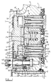
- FIG. 1 this illustrates a sliding caliper 1 of a disc brake mounted relative to a fixed carrier 2 in conventional manner by guide pins, of which one is illustrated at 3.
- the caliper 1 defines a chamber 4, closed by an end cover 5, housing an actuator and adjuster mechanism to be described in detail hereafter.
- the actuator is of a type, similar to that disclosed, for example in W093/22579, as will be understood by one versed in the art, and includes a rotary member 6, rotatable, in use, by a conventional power device, such as an air actuator (not shown), the member 6 being rotationally supported against the cover 5 by way of needle bearings 7.
- a conventional power device such as an air actuator (not shown)
- the member 6 being rotationally supported against the cover 5 by way of needle bearings 7.
- Portions 6A, 6B of the member 6 locate respective cylindrical rollers 8, 9, which are seated in respective part-cylindrical bearings 8', 9'.
- the axes of the rollers 8 and 9 and the portions 6A, 6B are offset from one another and form an eccentric arrangement with the rollers 8 and 9 bearing against adjacent adjustable force transmitting devices in the form of tappet assemblies 10, 11.
- the tappet assemblies are identical and only the assembly 11 will be described in detail.
- This assembly comprises an outer sleeve 12 which is internally threaded at 12A over a part of its length and within which is contained a shaft 13 having a complementary external thread 14 over substantially its entire length engaged with the sleeve thread 12A.
- the shaft 13 is provided at its outer end with a tappet head 15 which is releasably coupled to the shaft so as, conveniently, to be freely rotatable relative to the latter by means which will be described in detail hereafter.
- the sleeve 12 is rotatably mounted in the caliper body 1 by way of a low friction bearing sleeve 16 and is provided with an external gear form 17 which may be either a separate component firmly secured to the sleeve, as illustrated, or a formation integral with the latter.
- the gear form 17 meshes with a corresponding formation on a gear wheel 18 forming part of an adjuster mechanism indicated generally at 19 and also with an intermediate gear 20 which is freely rotatably mounted and located between the tappet assemblies 10 and 11.
- a head in the form of an end abutment 21 is engaged over the end of the sleeve 12 opposite to that carrying the tappet head 15 and is rigidly connected to or integral with a pin 22 which extends within the shaft 13 and has a non-circular shape engaging within a relatively short insert 13A non-rotatably mounted within the shaft.
- the pin 22 provides a guide for the shaft 13 during axial movement of the shaft between extreme retracted and extended positions thereof, and also serves to lock the shaft 13 against rotation.
- the pin 22 is of part-circular cross-section with a pair of opposed flats 22A for engagement with corresponding flats within the insert.
- the pin 22 and insert 13A may alternatively be non-rotatably interconnected by way of other suitable formations providing the necessary non-rotational connection whilst permitting axial sliding of the shaft 13 along the pin. It can be seen that the abutment 21 is keyed by the pin 22 and insert 13A against rotation relative to the shaft 13 and the abutment is itself prevented from rotation by engagement with a plate member 23 which also engages, in similar manner, a corresponding abutment 21 on the other tappet assembly 10, as will be further described.
- the plate member 23 carries a shaft in the form of a pin 24 which rotatably mounts the intermediate gear 20, a radial flange 25 of the pin providing an abutment for one end of a tappet return spring 26, the other end of which bears against an internal surface of the housing 1.
- FIG. 2 illustrates the manner of connecting the tappet head 15 to the shaft 13 in more detail in Figures 2 to 4.
- the connection is effected by way of a circlip 27 housed within a groove 28 of the shaft 13 and engaged behind a shoulder 29 of the tappet head.
- Figure 2 illustrates the component positions prior to assembly. The circlip is first inserted within the groove 28, which is relatively deep to permit compression of the circlip therein beyond its normal rest position.
- the circlip is provided with three or more peripherally spaced tags 27A which, when the tappet head is placed on the shaft and moved axially therealong, ride up a ramp 30 formed on the forward edge of the shoulder 29 which acts to press the circlip inwardly into the groove until it moves past the shoulder, whereupon the circlip resiliently recovers to become lodged behind the shoulder 29 and thereby provide the desired connection which normally precludes axial removal of the tappet head whilst permitting free rotation thereof relative to the shaft.
- the two components may be separated relatively easily, for servicing purposes for example, by compressing the circlip radially inwardly in conventional manner.
- Protection against the ingress of foreign material may conveniently be provided by a protective boot 15A secured around one of its peripheral extremities to the housing by way of an anchoring device 15B and around its other peripheral extremity to the tappet head 13 which carries a boot-protecting plate 15C.
- An advantage of making the tappet head detachable is that attachment and removal of the boot are facilitated and the risk of damaging the boot during its fitting and removal is much reduced.
- the circlip 27 used to secure the head 15 in place serves as a stop cooperating with an abutment 30A, shown as formed by the end of the sleeve 12, in order to limit retraction of the shaft 13 within the sleeve 12 when the tappets are de-adjusted for friction pad replacement and/or general servicing of the brake.
- This stop arrangement simplifies the assembly considerably by making use of an existing component to serve as the stop.
- the plate member 23 is forked at both of its ends and dimensioned so as partially to embrace the abutment 21 and engage respective flats 21A formed on opposed sides of the abutment, as well as engaging adjacent axially facing surfaces 21B.
- the force of the return spring 26 is applied, via the flange 25 of the pin 24 and the pin itself to the plate 23 and thence to the abutment 21 and the roller 9 engaged therewith. It will therefore be seen that the return spring force bypasses the gear wheel 20 and consequently the shaft 13 and sleeve 12 so that the frictional resistance occurring in the tappet assemblies 10,11 is very much reduced as compared with some conventional arrangements.
- the automatic adjuster mechanism 19 operates to lengthen the tappet assembly 11 to compensate for wear of the brake friction linings, the adjuster acting on the sleeve 12 of the tappet and, via the gear wheel 20, on the corresponding sleeve in the identical tappet 10.
- the eccentric member or shaft 6 is linked to the adjuster by way of a pin 31 forming a connection between the shaft 6 and a bush 32 of the adjuster.
- the bush 32 is coupled to a drive sleeve assembly comprising two generally cylindrical components 33, 34 arranged in axial succession around an adjuster shaft 35, the components being frictionally interconnected by way of a wrap spring 36 arranged to engage respective internal surfaces of the components.
- a multi-plate clutch assembly illustrated generally at 37, has one set of plates coupled to a cylindrical extension 38 of the component 34 and its other set of plates connected to an intermediate component 39 mounted on the shaft 35.
- the multi-plate clutch is also in driving engagement with the gear wheel 18 referred to previously, the clutch being pre-loaded by a spring 40.
- the normal running clearance of the brake is provided for by clearance between the component 34 and the part of the clutch 37 engaged therewith.
- the shaft 35 is provided with an inner hexagon formation 41 engaged with a corresponding internal formation within the gear wheel 18 and the shaft thus rotates permanently with the gear wheel.
- the outer end of the shaft 35 is provided also with a drive formation 42 which, in this embodiment, is hexagonal. This formation is normally disposed within a protective cap 43 which is securely mounted in the housing and removable to permit adjusting rotation of the shaft by way of the drive formation 42.
- Actuation of the brake by rotation of the eccentric shaft 6 results in rotation of the sleeve components 33, 34 and if the movement of the tappets does not exceed the nominal brake clearance, as would be the case for example with the linings in new condition, the sleeves will merely move by the amount of the built-in clearance and return to their original positions, without adjustment taking place.
- the clutch is caused to rotate, together with the intermediate component 39 and the gear wheel 18, thereby rotating the tappet sleeves 12 in a direction such as to wind out the shafts 13 and thereby lengthen the strut assemblies by an amount equal to the excess actuator movement. If the caliper is subjected to loads high enough to cause deflection of the brake components, operation of the adjustment will be prevented by slipping of the multi-plate clutch at a predetermined torque representing a maximum permitted load.
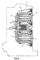
- the disc brake illustrated in Figures 5 and 6 is similar to that of Figures 1 to 4 and generally includes a caliper 1 slidably mounted relative to a fixed carrier and by guide pins, and housing an actuator and adjuster mechanism, as previously.
- This embodiment differs from the previous one, at least so far as concerns the mechanism interconnecting the sleeves 12 of the tappet assemblies 10, 11 so that rotary movement applied to one sleeve is transmitted to the other.
- This is again effected by way of an intermediate gear 40 which is freely rotatably mounted between the tappet assemblies 10 and 11 and has teeth 40A complementary to and meshing with those on the sleeves 12 of those assemblies.
- the intermediate gear 40 is journalled on a hub 41 urged firmly by a spring 42 against an anti-rotation plate 43 engaged against respective abutments 21 of the assemblies 11, 12.
- a spigot 41A extends through an opening in the plate 43 and a circlip 41B anchors the hub to the plate.
- the diameter of the hub 41 is such that the hub covers a major part of the adjacent surface of the plate 43, thereby to spread the load of the spring 42 over a relatively large support area.
- the end of the hub beyond the gear 40 in the direction away from the plate 43 is provided with a radially outwardly extending flange 44 between which and a snap ring 17A the gear is retained in position.
- the flange could be formed by a separate washer and snap-ring arrangement. It will be appreciated that any asymmetric loading of the gear 40 during operation of the adjuster assemblies will be resisted by the opposed flange and a large area of the plate 43, resulting in a mechanism providing good stability under extreme operating conditions.
- the hub 41 has a central axial stem 45 housed within a cylindrical can 46, the lower end of which, as seen in the drawing, has a radially outwardly extending flange 47 against which bears the lower end of the spring 42.
- a further smaller spring 48 is housed within the can and surrounds the upper end portion of the stem 45, and, depending upon the method of assembly, may or may not be firmly secured to the latter. This spring 48 takes no part in the operation of the mechanism, but serves to provide stability to part of the mechanism during its assembly into the housing, as will be described hereafter.
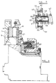
- FIG. 6 illustrates components of the brake prior to assembly of the cover plate 5 on to the brake body 1. It can be seen that the lever 6 and its bearings 7, together with the roller 8, the abutment 21 of the tappet assembly 11 and the anti-rotation plate 43 are assembled between the cover plate 5 and hub 41. Prior to assembly the latter is urged by the smaller spring 48 to a position axially displaced from its normal position in the assembled brake and the can 46 is displaced by the large spring 42 in the same direction until this spring has expanded to its full free length, as illustrated. The force of the spring 48 is thus transmitted through the hub and anti-rotation plate on to the component 21, and thereby serves to hold the components 6, 7 and 8 against the cover plate.
- Figure 7 illustrates a modification in which the hub 41 is replaced by a generally cylindrical element 50 of thin gauge metal or plastics material.
- the cylindrical wall 51 thereof fits closely within the gear 40 and acts as a journal for the latter.
- a base 52 of the element lies against the adjacent surface of the plate 43 over substantially the whole area of this surface.
- the force of the spring 42 acting on the base 52 by way of the flange 47 of the can 46 is transmitted to the base and thence to the plate 43.
- the gear 40 is supported between a radial flange 53 of the element and a spacer ring 54 of metal or plastics material.
- a separate stem 55 is provided having a cylindrical portion 56 extending through an opening in the plate 43 and being secured to the latter by, for example, peening its free end at 57 against the plate.
- the plate 43 and base 52 of the element 50 are trapped between a first shoulder 58 of the stem and the peened end portion of the latter.
- the smaller spring 48 is disposed between a further shoulder 59 of the stem and the can 46. Operation of this embodiment is similar to that of Figures 5 and 6 and has the advantage of providing additional cost-effectiveness as compared with the embodiment of Figures 5 and 6.
Landscapes
- Engineering & Computer Science (AREA)
- General Engineering & Computer Science (AREA)
- Mechanical Engineering (AREA)
- Braking Arrangements (AREA)
Abstract
Claims (7)
- Un frein à disque comprenant un boítier contenant, en service, au moins un élément de friction, un dispositif d'actionnement (6, 7, 8, 9) susceptible de fonctionner via au moins un dispositif (10, 11) de transmission de force pour déplacer l'élément de friction en contact avec un disque de frein rotatif, le ou chaque dispositif de transmission de force (10, 11) comportant deux pièces accrochées l'une à l'autre (12, 13) dont les positions relatives sont réglables automatiquement pour compenser l'usure de l'élément de friction, et un ressort de rappel (26) agencé pour exercer une force de rappel sur le dispositif d'actionnement (6, 7, 8, 9) le long d'une trajectoire qui ne passe pas par l'une ou l'autre des pièces (12, 13) accrochées l'une à l'autre.
- Un disque de frein selon la revendication 1, dans lequel la force de rappel exercée par le ressort (26) contourne les pièces (12, 13) accrochées l'une à l'autre via un arbre (24, 45, 55) et un élément (23, 43) agencé pour transmettre la force de rappel au dispositif d'actionnement (6, 7, 8, 9) via un composant librement mobile (21) associé à le ou à chaque dispositif de transmission de force (10, 11).
- Un disque de frein selon la revendication 1 ou 2, dans lequel sont prévus deux dispositifs (10, 11) de transmission de force, des structures respectives de roue d'engrenage (17) sur des composants rotatifs (12) de ces dispositifs sont interconnectés par une roue d'engrenage intermédiaire (20) qui transmet la rotation d'un composant (12) à l'autre (12), la roue d'engrenage intermédiaire (20) étant supportée à rotation sur l'arbre (24, 45, 55) qui assure également une butée axiale pour réagir à la force de rappel, l'arbre (25) venant en butée sur l'élément (23, 43) agencé pour transmettre la force de rappel au dispositif d'actionnement via un composant (21) librement mobile axialement et associé à chaque dispositif de transmission de force (10, 11).
- Un disque de frein selon la revendication 2 ou 3, dans lequel le ou chaque composant (21) axialement mobile, coopère avec un organe correspondant respectif (13) du ou de chaque dispositif de transmission de force (10, 11) pour verrouiller le ou chaque organe (13) en rotation par rapport à le ou à chaque composant (21) axialement mobile.
- Un disque de frein selon la revendication 2, 3 ou 4, dans lequel le diamètre de la partie axialement en butée de l'arbre (24, 45, 55) est tel qu'il met en butée l'élément (23, 43) transmettant la force de rappel sur une majeure partie de la surface de ce dernier, de manière à répartir la charge de rappel sur une zone de support relativement importante.
- Un disque de frein selon l'une quelconque des revendications 2 à 5, dans lequel la force du ressort de rappel est appliquée via une enveloppe creuse (46) logeant un ressort secondaire (48) servant à appliquer une force de stabilisation via l'arbre (45, 55) aux composants de l'organe d'actionnement pendant l'assemblage dans le boítier mais qui est rendue inactive après cet assemblage.
- Un disque de frein selon la revendication 6, dans lequel le ressort secondaire (48) est fixé à l'arbre (45, 55) de façon à empêcher sa séparation axiale de ce dernier.
Priority Applications (1)
| Application Number | Priority Date | Filing Date | Title |
|---|---|---|---|
| EP00106942A EP1013958B1 (fr) | 1995-06-20 | 1996-06-20 | Frein et son actionneur |
Applications Claiming Priority (5)
| Application Number | Priority Date | Filing Date | Title |
|---|---|---|---|
| GBGB9512522.5A GB9512522D0 (en) | 1995-06-20 | 1995-06-20 | Brake and actuator therefor |
| GB9512522 | 1995-06-20 | ||
| GB9603159 | 1996-02-15 | ||
| GBGB9603159.6A GB9603159D0 (en) | 1996-02-15 | 1996-02-15 | Brake and actuator therefor |
| PCT/GB1996/001476 WO1997001045A1 (fr) | 1995-06-20 | 1996-06-20 | Frein a disque |
Related Child Applications (1)
| Application Number | Title | Priority Date | Filing Date |
|---|---|---|---|
| EP00106942A Division EP1013958B1 (fr) | 1995-06-20 | 1996-06-20 | Frein et son actionneur |
Publications (2)
| Publication Number | Publication Date |
|---|---|
| EP0834026A1 EP0834026A1 (fr) | 1998-04-08 |
| EP0834026B1 true EP0834026B1 (fr) | 2002-09-11 |
Family
ID=26307248
Family Applications (2)
| Application Number | Title | Priority Date | Filing Date |
|---|---|---|---|
| EP00106942A Expired - Lifetime EP1013958B1 (fr) | 1995-06-20 | 1996-06-20 | Frein et son actionneur |
| EP96918771A Expired - Lifetime EP0834026B1 (fr) | 1995-06-20 | 1996-06-20 | Frein a disque |
Family Applications Before (1)
| Application Number | Title | Priority Date | Filing Date |
|---|---|---|---|
| EP00106942A Expired - Lifetime EP1013958B1 (fr) | 1995-06-20 | 1996-06-20 | Frein et son actionneur |
Country Status (6)
| Country | Link |
|---|---|
| EP (2) | EP1013958B1 (fr) |
| JP (1) | JPH11508022A (fr) |
| KR (1) | KR19990022974A (fr) |
| BR (1) | BR9608957A (fr) |
| DE (2) | DE69633257T2 (fr) |
| WO (1) | WO1997001045A1 (fr) |
Cited By (2)
| Publication number | Priority date | Publication date | Assignee | Title |
|---|---|---|---|---|
| CN102112774B (zh) * | 2008-07-30 | 2014-12-31 | 克诺尔商用车制动系统有限公司 | 用于盘式制动器的调节装置 |
| EP3757418B1 (fr) * | 2019-06-27 | 2023-11-15 | ZF CV Systems Global GmbH | Frein à disque pour véhicules, en particulier pour des véhicules commerciaux |
Families Citing this family (15)
| Publication number | Priority date | Publication date | Assignee | Title |
|---|---|---|---|---|
| DE19636943A1 (de) * | 1996-09-11 | 1998-03-12 | Perrot Bremsen Gmbh | Sattelscheibenbremse |
| SE511562C2 (sv) * | 1997-04-28 | 1999-10-18 | Volvo Lastvagnar Ab | Justeranordning avseende förslitning av bromsbelägg |
| GB9806542D0 (en) | 1998-03-26 | 1998-05-27 | Lucas Ind Plc | Disc brake actuator |
| GB9817624D0 (en) * | 1998-08-14 | 1998-10-07 | Lucas Ind Plc | Disk brake actuator |
| FR2914033B1 (fr) * | 2007-03-22 | 2009-05-01 | Bosch Gmbh Robert | Frein a disque comportant un etrier muni d'un joint cache-poussiere ameliore. |
| DE102012014886A1 (de) * | 2012-07-26 | 2014-01-30 | Knorr-Bremse Systeme für Nutzfahrzeuge GmbH | Zuspanneinrichtung einer Scheibenbremse für ein Nutzfahrzeug |
| DE102013101636A1 (de) | 2013-02-19 | 2014-08-21 | Bpw Bergische Achsen Kg | Scheibenbremse für Fahrzeuge |
| DE102013101087B4 (de) * | 2013-02-04 | 2022-03-17 | Bpw Bergische Achsen Kg | Mehrfachstempel-Scheibenbremse |
| DE102015104183A1 (de) * | 2015-03-20 | 2016-09-22 | Knorr-Bremse Systeme für Nutzfahrzeuge GmbH | Scheibenbremse für ein Nutzfahrzeug |
| DE102015119194A1 (de) | 2015-11-09 | 2017-05-11 | Knorr-Bremse Systeme für Nutzfahrzeuge GmbH | Scheibenbremse für ein Nutzfahrzeug |
| DE102016112265A1 (de) * | 2016-07-05 | 2018-01-11 | Knorr-Bremse Systeme für Nutzfahrzeuge GmbH | Scheibenbremse für ein Nutzfahrzeug |
| DE202017002779U1 (de) * | 2017-05-26 | 2017-06-26 | Haldex Brake Products Ab | Scheibenbremse und Bremsbetätigungsmechanismus |
| DE102019126584A1 (de) * | 2019-10-02 | 2021-04-08 | Knorr-Bremse Systeme für Nutzfahrzeuge GmbH | Bremsstempel einer Scheibenbremse eines Nutzfahrzeugs und Scheibenbremse |
| DE102021126764B4 (de) | 2021-10-15 | 2025-08-28 | Knorr-Bremse Systeme für Nutzfahrzeuge GmbH | Bremsstempel einer Scheibenbremse, Zuspanneinrichtung und Scheibenbremse |
| DE102022125922A1 (de) * | 2022-10-07 | 2024-04-18 | Knorr-Bremse Systeme für Nutzfahrzeuge GmbH | Bremsstempel für eine Scheibenbremse eines Nutzfahrzeugs |
Family Cites Families (4)
| Publication number | Priority date | Publication date | Assignee | Title |
|---|---|---|---|---|
| GB8324942D0 (en) * | 1983-09-17 | 1983-10-19 | Lucas Ind Plc | Actuator assemblies for vehicle brakes |
| GB8529720D0 (en) * | 1985-12-03 | 1986-01-08 | Lucas Ind Plc | Brake adjusters |
| DE4212352A1 (de) * | 1992-04-13 | 1993-10-14 | Knorr Bremse Ag | Druckluftbetätigte Scheibenbremse |
| DE59301481D1 (de) * | 1992-05-05 | 1996-02-29 | Lucas Ind Plc | Betätigungsvorrichtung mit selbsttätiger nachstellung an scheibenbremsen, insbesondere für lastkraftwagen und omnibusse |
-
1996
- 1996-06-20 BR BR9608957A patent/BR9608957A/pt not_active IP Right Cessation
- 1996-06-20 KR KR1019970709444A patent/KR19990022974A/ko not_active Withdrawn
- 1996-06-20 JP JP9503667A patent/JPH11508022A/ja not_active Ceased
- 1996-06-20 EP EP00106942A patent/EP1013958B1/fr not_active Expired - Lifetime
- 1996-06-20 DE DE69633257T patent/DE69633257T2/de not_active Expired - Lifetime
- 1996-06-20 WO PCT/GB1996/001476 patent/WO1997001045A1/fr not_active Ceased
- 1996-06-20 DE DE69623621T patent/DE69623621T2/de not_active Expired - Lifetime
- 1996-06-20 EP EP96918771A patent/EP0834026B1/fr not_active Expired - Lifetime
Cited By (2)
| Publication number | Priority date | Publication date | Assignee | Title |
|---|---|---|---|---|
| CN102112774B (zh) * | 2008-07-30 | 2014-12-31 | 克诺尔商用车制动系统有限公司 | 用于盘式制动器的调节装置 |
| EP3757418B1 (fr) * | 2019-06-27 | 2023-11-15 | ZF CV Systems Global GmbH | Frein à disque pour véhicules, en particulier pour des véhicules commerciaux |
Also Published As
| Publication number | Publication date |
|---|---|
| DE69623621T2 (de) | 2003-08-07 |
| EP0834026A1 (fr) | 1998-04-08 |
| WO1997001045A1 (fr) | 1997-01-09 |
| BR9608957A (pt) | 1999-03-02 |
| EP1013958A2 (fr) | 2000-06-28 |
| DE69623621D1 (de) | 2002-10-17 |
| DE69633257T2 (de) | 2005-09-15 |
| DE69633257D1 (de) | 2004-09-30 |
| KR19990022974A (ko) | 1999-03-25 |
| EP1013958A3 (fr) | 2000-08-16 |
| EP1013958B1 (fr) | 2004-08-25 |
| JPH11508022A (ja) | 1999-07-13 |
Similar Documents
| Publication | Publication Date | Title |
|---|---|---|
| EP0834026B1 (fr) | Frein a disque | |
| EP0877873B1 (fr) | Capteur d'usure de freins | |
| EP0877872B1 (fr) | Detecteur d'usure de freins | |
| CA1183465A (fr) | Dispositif de reprise automatique du jeu aux freins | |
| CA1194816A (fr) | Dispositif de reprise automatique de jeu | |
| CN110088496B (zh) | 盘式制动器和制动器致动机构 | |
| JPH09507559A (ja) | 特に重車両用のディスクブレーキのパッド押しつけ装置 | |
| JP2001522441A (ja) | ブレーキライニング磨耗調節器アセンブリ | |
| PL169820B1 (en) | Pressure-operated control system for vehicle brakes | |
| EP0154398B1 (fr) | Dispositif d'actionnement de frein | |
| EP2738413B1 (fr) | Régleur de frein à disque à air pour jeu fonctionnel amélioré | |
| US6293371B1 (en) | Disc brake assembly | |
| CA1059044A (fr) | Tendeurs automatiques pour timoneries de freins de vehicules | |
| EP0225764B1 (fr) | Dispositif de rattrapage de jeu pour freins | |
| US12060916B2 (en) | Disk brake | |
| CA1137885A (fr) | Dispositif de reprise du jeu sur des tiges de pistons | |
| GB1588263A (en) | Hydraulic brake actuator having a wear adjusting device | |
| EP0471496A1 (fr) | Ajusteur automatique pour freins | |
| CA1169366A (fr) | Mecanisme de reprise du jeu pour tige-poussoir | |
| US4732243A (en) | Automatic adjuster for a vehicle brake actuator | |
| EP0225791A1 (fr) | Actuateur de freins |
Legal Events
| Date | Code | Title | Description |
|---|---|---|---|
| PUAI | Public reference made under article 153(3) epc to a published international application that has entered the european phase |
Free format text: ORIGINAL CODE: 0009012 |
|
| 17P | Request for examination filed |
Effective date: 19971210 |
|
| AK | Designated contracting states |
Kind code of ref document: A1 Designated state(s): DE GB SE |
|
| 17Q | First examination report despatched |
Effective date: 19981222 |
|
| RAP1 | Party data changed (applicant data changed or rights of an application transferred) |
Owner name: MERITOR AUTOMOTIVE, INC. |
|
| GRAG | Despatch of communication of intention to grant |
Free format text: ORIGINAL CODE: EPIDOS AGRA |
|
| GRAG | Despatch of communication of intention to grant |
Free format text: ORIGINAL CODE: EPIDOS AGRA |
|
| GRAH | Despatch of communication of intention to grant a patent |
Free format text: ORIGINAL CODE: EPIDOS IGRA |
|
| RAP1 | Party data changed (applicant data changed or rights of an application transferred) |
Owner name: ARVINMERITOR, INC. |
|
| GRAH | Despatch of communication of intention to grant a patent |
Free format text: ORIGINAL CODE: EPIDOS IGRA |
|
| GRAA | (expected) grant |
Free format text: ORIGINAL CODE: 0009210 |
|
| AK | Designated contracting states |
Kind code of ref document: B1 Designated state(s): DE GB SE |
|
| REG | Reference to a national code |
Ref country code: GB Ref legal event code: FG4D |
|
| REF | Corresponds to: |
Ref document number: 69623621 Country of ref document: DE Date of ref document: 20021017 |
|
| PLBE | No opposition filed within time limit |
Free format text: ORIGINAL CODE: 0009261 |
|
| STAA | Information on the status of an ep patent application or granted ep patent |
Free format text: STATUS: NO OPPOSITION FILED WITHIN TIME LIMIT |
|
| 26N | No opposition filed |
Effective date: 20030612 |
|
| PGFP | Annual fee paid to national office [announced via postgrant information from national office to epo] |
Ref country code: GB Payment date: 20150629 Year of fee payment: 20 Ref country code: SE Payment date: 20150629 Year of fee payment: 20 Ref country code: DE Payment date: 20150629 Year of fee payment: 20 |
|
| REG | Reference to a national code |
Ref country code: DE Ref legal event code: R071 Ref document number: 69623621 Country of ref document: DE |
|
| REG | Reference to a national code |
Ref country code: GB Ref legal event code: PE20 Expiry date: 20160619 |
|
| PG25 | Lapsed in a contracting state [announced via postgrant information from national office to epo] |
Ref country code: GB Free format text: LAPSE BECAUSE OF EXPIRATION OF PROTECTION Effective date: 20160619 |
|
| REG | Reference to a national code |
Ref country code: SE Ref legal event code: EUG |