EP0833434A1 - Synchronisationsverfahren- und Vorrichtung für eine dreiphasige Synchronmaschine - Google Patents
Synchronisationsverfahren- und Vorrichtung für eine dreiphasige Synchronmaschine Download PDFInfo
- Publication number
- EP0833434A1 EP0833434A1 EP97402220A EP97402220A EP0833434A1 EP 0833434 A1 EP0833434 A1 EP 0833434A1 EP 97402220 A EP97402220 A EP 97402220A EP 97402220 A EP97402220 A EP 97402220A EP 0833434 A1 EP0833434 A1 EP 0833434A1
- Authority
- EP
- European Patent Office
- Prior art keywords
- motor
- signals
- supply
- rotor
- phase
- Prior art date
- Legal status (The legal status is an assumption and is not a legal conclusion. Google has not performed a legal analysis and makes no representation as to the accuracy of the status listed.)
- Granted
Links
Images


Classifications
-
- H—ELECTRICITY
- H02—GENERATION; CONVERSION OR DISTRIBUTION OF ELECTRIC POWER
- H02P—CONTROL OR REGULATION OF ELECTRIC MOTORS, ELECTRIC GENERATORS OR DYNAMO-ELECTRIC CONVERTERS; CONTROLLING TRANSFORMERS, REACTORS OR CHOKE COILS
- H02P6/00—Arrangements for controlling synchronous motors or other dynamo-electric motors using electronic commutation dependent on the rotor position; Electronic commutators therefor
- H02P6/20—Arrangements for starting
-
- H—ELECTRICITY
- H02—GENERATION; CONVERSION OR DISTRIBUTION OF ELECTRIC POWER
- H02P—CONTROL OR REGULATION OF ELECTRIC MOTORS, ELECTRIC GENERATORS OR DYNAMO-ELECTRIC CONVERTERS; CONTROLLING TRANSFORMERS, REACTORS OR CHOKE COILS
- H02P6/00—Arrangements for controlling synchronous motors or other dynamo-electric motors using electronic commutation dependent on the rotor position; Electronic commutators therefor
- H02P6/14—Electronic commutators
- H02P6/16—Circuit arrangements for detecting position
Definitions
- the present invention relates to methods and devices for synchronizing the supply of a three-phase synchronous motor.
- the electrical angle is equal to the mechanical angle, i.e. a period of control signals corresponds to one revolution of the rotor.
- windings B1, B2 and B3 of the stator of this motor are for example supplied by three signals G1, G2 and G3 as shown in Figures 2a to 2c.
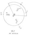
- These sensors C1 to C3 are for example Hall effect cells distributed around the stator in being offset by 120 ° with respect to each other, as shown in Figure 1.
- the rotor then has a magnetic sector S 120 ° opening which cooperates with these three sensors C1 to C3.
- each sensor Ci is the signal Gi which must be applied to the coil Bi. At stake en route, it suffices to supply the coil Gi, the associated Ci sensor is high and the motor started.
- the angular position of the rotor is provided by means detection systems which include either multiple sensors hall effect, i.e. means for voltage measurement relating to the different windings.
- the solution according to the invention consists of a motor power synchronization method electric three-phase synchronous, especially for vehicle automobile, characterized in that the supply signals of the different phases of said motor on the same signal which characterizes the position of the rotation of the rotor of said motor and in that for start the said motor, the three phases of the motor by three phase shift supply signals two to two of 2 ⁇ / 3 and in that if the engine remains blocked, we changes the power supply of the different phases of the motor to supply them with the same signals, phase shifted by 2 ⁇ / 3.
- Such a command allows the synchronization of feeding a motor on a single signal.
- the invention also provides a device allowing the implementation of this process.
- the three-phase synchronous motor illustrated in the Figure 3 is a motor with a pair of poles comprising three windings B1, B2 and B3 whose signals power are generated by a single sensor vs.
- This sensor C is for example an effect sensor Hall which cooperates with a wheel integral with the rotor, which has three magnetic sectors S1, S2 and S3 with 60 ° opening evenly distributed over the total rotor circumference.
- the signal Sc supplied by the sensor C is that which is illustrated in figure 4.
- the coils are supplied with signals G1 to G3 must be - modulo 3 - in the order B i0 , B i0 + 1 , B i0 + 2 , B i0 .
- the problem arises from the fact that we do not know which is the coil B i0 which must be supplied first, since we do not know a priori the initial position of the rotor.
- FIG. 5 An assembly allowing the generation of signals supply Gi from the signal Sc given by the sensor C has been illustrated in FIG. 5.
- Such an assembly includes an integrated circuit of type CD 4017 BE which receives the signal Sc as input.
- Such a circuit functions as a divider by three frequency.
- the fourth output is connected to an input of resetting of said circuit, which restarts the 1 logic on the first output (signal G1).
- the invention has just been described in the simple case of a motor with a pair of poles, but can be generalized to any engine with 2 (resp. n) pairs of poles.
- phases I, II and III signals of Figures 3a to 3c no longer correspond than 1/2 (1 / nth of) full rotation of the rotor (the angle different from the mechanical angle).
- the synchronization process is also unchanged.
- the power signals can be, so as to soften the engine control and to have a more regular torque, signals are covering, the signals G1, G2 and G3 that we have shown in Figures 2a to 2c with which the above description was made having been here retained to allow a better understanding of the invention.
- sensors for example coding wheels, or means which include means for generating a light beam (diode lamp or lamp) and a cell photoelectric.
- the invention finds in particular advantageously applied in the case of motors electronically, for example from fan motors motor vehicles.
- the synchronization device the supply of a three-phase motor proposed by the invention comprises means for synchronizing the supply signals of the different phases of said motor on the same signal at the output of a sensor for the characterization of rotor rotation and means to power the three phases when the engine starts of the motor by three phase shifted supply signals two two by 2 ⁇ / 3 and for, if the engine remains blocked, change the power of the different phases of said motor to supply them with the same signals, phase shifted by 2 ⁇ / 3.
- Power signals are signals in slot, the signal on which said signals are synchronized being a niche signal whose different transitions trigger transitions said supply signals.
Landscapes
- Engineering & Computer Science (AREA)
- Power Engineering (AREA)
- Control Of Motors That Do Not Use Commutators (AREA)
- Control Of Ac Motors In General (AREA)
Applications Claiming Priority (2)
| Application Number | Priority Date | Filing Date | Title |
|---|---|---|---|
| FR9611794A FR2754116B1 (fr) | 1996-09-27 | 1996-09-27 | Procede et dispositif de synchronisation d'un moteur synchrone triphase |
| FR9611794 | 1996-09-27 |
Publications (2)
| Publication Number | Publication Date |
|---|---|
| EP0833434A1 true EP0833434A1 (de) | 1998-04-01 |
| EP0833434B1 EP0833434B1 (de) | 2003-10-22 |
Family
ID=9496122
Family Applications (1)
| Application Number | Title | Priority Date | Filing Date |
|---|---|---|---|
| EP97402220A Expired - Lifetime EP0833434B1 (de) | 1996-09-27 | 1997-09-24 | Synchronisationsverfahren- und Vorrichtung für den Anlauf einer dreiphasigen Synchronmaschine |
Country Status (6)
| Country | Link |
|---|---|
| US (1) | US5973461A (de) |
| EP (1) | EP0833434B1 (de) |
| JP (1) | JPH10127081A (de) |
| DE (1) | DE69725673T2 (de) |
| ES (1) | ES2210475T3 (de) |
| FR (1) | FR2754116B1 (de) |
Cited By (2)
| Publication number | Priority date | Publication date | Assignee | Title |
|---|---|---|---|---|
| US7348684B2 (en) * | 2004-08-03 | 2008-03-25 | Bayerische Motoren Werke Aktiengesellschaft | Drive unit |
| WO2020001904A1 (fr) * | 2018-06-29 | 2020-01-02 | Valeo Systemes D'essuyage | Moteur electrique a courant continu sans balai et procede de commande associe |
Families Citing this family (7)
| Publication number | Priority date | Publication date | Assignee | Title |
|---|---|---|---|---|
| US6349796B1 (en) | 1999-09-17 | 2002-02-26 | Mitsubishi Denki Kabushiki Kaisha | Starting drive control for elevator |
| US6344089B1 (en) | 1977-08-15 | 2002-02-05 | Mitsubishi Denki Kabushiki Kaisha | Drive control for elevator |
| JP3226551B2 (ja) * | 1997-03-18 | 2001-11-05 | 三菱電機株式会社 | エレベータ用巻き上げ装置 |
| JPH11356088A (ja) * | 1998-06-08 | 1999-12-24 | Matsushita Electric Ind Co Ltd | ブラシレスモータの駆動装置 |
| US6891343B2 (en) * | 2003-03-14 | 2005-05-10 | Petersen Technology Corporation | Multiphase motors with single point sensing based commutation |
| KR101201908B1 (ko) * | 2006-05-04 | 2012-11-16 | 엘지전자 주식회사 | 동기 릴럭턴스 모터의 제어 장치 및 방법 |
| CN107968540A (zh) * | 2017-12-27 | 2018-04-27 | 北京信息科技大学 | 磁悬浮无刷直流电机用轴向位移与转子位置集成传感器 |
Citations (6)
| Publication number | Priority date | Publication date | Assignee | Title |
|---|---|---|---|---|
| DE3325610A1 (de) * | 1982-07-15 | 1984-01-19 | Kabushiki Kaisha Sankyo Seiki Seisakusho, Nagano | Buerstenloser gleichstrommotor |
| FR2590423A1 (fr) * | 1985-11-21 | 1987-05-22 | Valeo | Procede et dispositif pour assurer le demarrage d'un moteur electrique a commutation electronique |
| DE4305321A1 (de) * | 1992-02-21 | 1993-08-26 | Gold Star Co | |
| US5432414A (en) * | 1992-03-30 | 1995-07-11 | Kabushiki Kaisha Toshiba | Sensorless spindle motor control apparatus |
| WO1995024071A1 (en) * | 1994-03-03 | 1995-09-08 | Iomega Corporation | Servo motor controller using position interpolation |
| EP0713286A2 (de) * | 1993-06-07 | 1996-05-22 | Switched Reluctance Drives Ltd | Verfahren zum Anlaufen einer elektrischen Maschine |
Family Cites Families (8)
| Publication number | Priority date | Publication date | Assignee | Title |
|---|---|---|---|---|
| JPS5378011A (en) * | 1976-12-21 | 1978-07-11 | Mitsubishi Electric Corp | Electric valve feeding motor apparatus commutated by internal electromotive force |
| NL8103835A (nl) * | 1981-08-17 | 1983-03-16 | Philips Nv | Zelfaanlopende collectorloze gelijkstroommotor. |
| US4620139A (en) * | 1985-07-22 | 1986-10-28 | Kabushiki Kaisha Shicoh Giken | Brushless d.c. motor |
| US4755728A (en) * | 1986-09-16 | 1988-07-05 | Itsuki Ban | Single-phase semiconductor electric motor and fan using the same |
| US4737674A (en) * | 1986-10-17 | 1988-04-12 | Shicoh Engineering Co., Ltd. | Single phase brushless motor with a core |
| AU656885B2 (en) * | 1989-10-27 | 1995-02-23 | Satake Engineering Co. Ltd. | Multiple-stator synchronous induction motor |
| US5323094A (en) * | 1992-02-24 | 1994-06-21 | Nippon Densen Corporation | Method of starting a sensorless multiphase dc motor |
| JP3250599B2 (ja) * | 1995-07-14 | 2002-01-28 | ティアック株式会社 | ブラシレスモ−タ |
-
1996
- 1996-09-27 FR FR9611794A patent/FR2754116B1/fr not_active Expired - Fee Related
-
1997
- 1997-09-24 EP EP97402220A patent/EP0833434B1/de not_active Expired - Lifetime
- 1997-09-24 DE DE69725673T patent/DE69725673T2/de not_active Expired - Fee Related
- 1997-09-24 ES ES97402220T patent/ES2210475T3/es not_active Expired - Lifetime
- 1997-09-25 US US08/936,990 patent/US5973461A/en not_active Expired - Fee Related
- 1997-09-29 JP JP9263077A patent/JPH10127081A/ja active Pending
Patent Citations (6)
| Publication number | Priority date | Publication date | Assignee | Title |
|---|---|---|---|---|
| DE3325610A1 (de) * | 1982-07-15 | 1984-01-19 | Kabushiki Kaisha Sankyo Seiki Seisakusho, Nagano | Buerstenloser gleichstrommotor |
| FR2590423A1 (fr) * | 1985-11-21 | 1987-05-22 | Valeo | Procede et dispositif pour assurer le demarrage d'un moteur electrique a commutation electronique |
| DE4305321A1 (de) * | 1992-02-21 | 1993-08-26 | Gold Star Co | |
| US5432414A (en) * | 1992-03-30 | 1995-07-11 | Kabushiki Kaisha Toshiba | Sensorless spindle motor control apparatus |
| EP0713286A2 (de) * | 1993-06-07 | 1996-05-22 | Switched Reluctance Drives Ltd | Verfahren zum Anlaufen einer elektrischen Maschine |
| WO1995024071A1 (en) * | 1994-03-03 | 1995-09-08 | Iomega Corporation | Servo motor controller using position interpolation |
Cited By (3)
| Publication number | Priority date | Publication date | Assignee | Title |
|---|---|---|---|---|
| US7348684B2 (en) * | 2004-08-03 | 2008-03-25 | Bayerische Motoren Werke Aktiengesellschaft | Drive unit |
| WO2020001904A1 (fr) * | 2018-06-29 | 2020-01-02 | Valeo Systemes D'essuyage | Moteur electrique a courant continu sans balai et procede de commande associe |
| FR3083402A1 (fr) * | 2018-06-29 | 2020-01-03 | Valeo Systemes D'essuyage | Moteur electrique a courant continu sans balai et procede de commande associe |
Also Published As
| Publication number | Publication date |
|---|---|
| DE69725673T2 (de) | 2004-08-12 |
| ES2210475T3 (es) | 2004-07-01 |
| EP0833434B1 (de) | 2003-10-22 |
| FR2754116A1 (fr) | 1998-04-03 |
| US5973461A (en) | 1999-10-26 |
| DE69725673D1 (de) | 2003-11-27 |
| FR2754116B1 (fr) | 1998-12-18 |
| JPH10127081A (ja) | 1998-05-15 |
Similar Documents
| Publication | Publication Date | Title |
|---|---|---|
| EP2338220A2 (de) | Hybridmaschine, die einen synchronmotor und einen asynchronmotor umfasst | |
| EP0833434B1 (de) | Synchronisationsverfahren- und Vorrichtung für den Anlauf einer dreiphasigen Synchronmaschine | |
| FR2811824A1 (fr) | Moteur electrique a deux modes de communication d'alimentation | |
| FR2458940A1 (fr) | Dispositif d'attaque de moteur a courant continu sans balai | |
| WO2018091302A1 (fr) | Moto-reducteur, systeme d'essuyage et procede de commande associes | |
| FR2484167A1 (fr) | Circuit de commande d'arret pour un moteur a courant continu sans collecteur | |
| EP0363264A1 (de) | Synchronmotor, dessen Drehrichtung gewählt werden kann | |
| EP1790067B1 (de) | Steuer- und stromversorgungsmodul für eine rotierende elektrische maschine | |
| EP1398869B1 (de) | Prozess und Rechner zur Bestimmung des Drehwinkels eines Rotors in Ruhelage, Steuereinheit und System unter Verwendung des Rechners | |
| EP0120723B1 (de) | Verfahren und Vorrichtung zur Feststellung der Geschwindigkeitsverminderung eines Gleichstrommotors sowie Motor mit einer derartigen Vorrichtung | |
| FR2478400A1 (fr) | Dispositif de commande d'un moteur electrique | |
| EP0936728B1 (de) | Regelung eines Unsymmetrien enthaltenden bürstenlosen Motors | |
| EP3167543B1 (de) | Verfahren zur erzeugung von steuersignalen zur verwaltung des betriebs eines synchronmotors, steuerungsvorrichtung und aktuator | |
| FR2660126A1 (fr) | Procede de commande d'un moteur synchrone autopilote et dispositif pour sa mise en óoeuvre. | |
| FR2590423A1 (fr) | Procede et dispositif pour assurer le demarrage d'un moteur electrique a commutation electronique | |
| FR2842041A1 (fr) | Module de controle et de puissance d'un alterno-demarreur integrable | |
| WO2020001904A1 (fr) | Moteur electrique a courant continu sans balai et procede de commande associe | |
| EP3602753B1 (de) | Verfeinerung einer synchronmaschine mit permanentmagneten | |
| FR3058594A1 (fr) | Procede de controle du demarrage d'un moteur electrique synchrone triphase sans collecteur | |
| EP2605400A1 (de) | Steuerverfahren eines Wechselrichters für die Stromversorgung eines Motors, und entsprechendes Steuermodul | |
| EP3121366B1 (de) | Verfahren zur erkennung der bewegungsrichtung einer verdunkelungsblende | |
| FR2843248A1 (fr) | Procede de commande de fonctionnement synchronise d'au moins deux moteurs electriques polyphases | |
| EP3121365B1 (de) | Verfahren zur erkennung der bewegungsrichtung einer verdunkelungsblende | |
| FR2608860A1 (fr) | Micromoteur synchrone autopilote | |
| FR2636182A1 (fr) | Circuit de commande pour moteur a courant continu sans collecteur, notamment d'un ventilateur |
Legal Events
| Date | Code | Title | Description |
|---|---|---|---|
| PUAI | Public reference made under article 153(3) epc to a published international application that has entered the european phase |
Free format text: ORIGINAL CODE: 0009012 |
|
| AK | Designated contracting states |
Kind code of ref document: A1 Designated state(s): DE ES GB IT |
|
| 17P | Request for examination filed |
Effective date: 19980907 |
|
| AKX | Designation fees paid |
Free format text: DE ES GB IT |
|
| RBV | Designated contracting states (corrected) |
Designated state(s): DE ES GB IT |
|
| 17Q | First examination report despatched |
Effective date: 20020627 |
|
| GRAH | Despatch of communication of intention to grant a patent |
Free format text: ORIGINAL CODE: EPIDOS IGRA |
|
| RTI1 | Title (correction) |
Free format text: SYNCHRONISING METHOD AND DEVICE FOR STARTING A SYNCHRONOUS MOTOR |
|
| GRAS | Grant fee paid |
Free format text: ORIGINAL CODE: EPIDOSNIGR3 |
|
| GRAA | (expected) grant |
Free format text: ORIGINAL CODE: 0009210 |
|
| AK | Designated contracting states |
Kind code of ref document: B1 Designated state(s): DE ES GB IT |
|
| REG | Reference to a national code |
Ref country code: GB Ref legal event code: FG4D Free format text: NOT ENGLISH |
|
| REF | Corresponds to: |
Ref document number: 69725673 Country of ref document: DE Date of ref document: 20031127 Kind code of ref document: P |
|
| GBT | Gb: translation of ep patent filed (gb section 77(6)(a)/1977) |
Effective date: 20031217 |
|
| REG | Reference to a national code |
Ref country code: ES Ref legal event code: FG2A Ref document number: 2210475 Country of ref document: ES Kind code of ref document: T3 |
|
| PLBE | No opposition filed within time limit |
Free format text: ORIGINAL CODE: 0009261 |
|
| STAA | Information on the status of an ep patent application or granted ep patent |
Free format text: STATUS: NO OPPOSITION FILED WITHIN TIME LIMIT |
|
| 26N | No opposition filed |
Effective date: 20040723 |
|
| PGFP | Annual fee paid to national office [announced via postgrant information from national office to epo] |
Ref country code: GB Payment date: 20060831 Year of fee payment: 10 |
|
| PGFP | Annual fee paid to national office [announced via postgrant information from national office to epo] |
Ref country code: DE Payment date: 20060907 Year of fee payment: 10 |
|
| PGFP | Annual fee paid to national office [announced via postgrant information from national office to epo] |
Ref country code: ES Payment date: 20060912 Year of fee payment: 10 |
|
| PGFP | Annual fee paid to national office [announced via postgrant information from national office to epo] |
Ref country code: IT Payment date: 20060930 Year of fee payment: 10 |
|
| GBPC | Gb: european patent ceased through non-payment of renewal fee |
Effective date: 20070924 |
|
| PG25 | Lapsed in a contracting state [announced via postgrant information from national office to epo] |
Ref country code: DE Free format text: LAPSE BECAUSE OF NON-PAYMENT OF DUE FEES Effective date: 20080401 |
|
| PG25 | Lapsed in a contracting state [announced via postgrant information from national office to epo] |
Ref country code: GB Free format text: LAPSE BECAUSE OF NON-PAYMENT OF DUE FEES Effective date: 20070924 |
|
| REG | Reference to a national code |
Ref country code: ES Ref legal event code: FD2A Effective date: 20070925 |
|
| PG25 | Lapsed in a contracting state [announced via postgrant information from national office to epo] |
Ref country code: ES Free format text: LAPSE BECAUSE OF NON-PAYMENT OF DUE FEES Effective date: 20070925 |
|
| PG25 | Lapsed in a contracting state [announced via postgrant information from national office to epo] |
Ref country code: IT Free format text: LAPSE BECAUSE OF NON-PAYMENT OF DUE FEES Effective date: 20070924 |