EP0833424A2 - Netzspeisungsauswahlschaltung für eine stromführende Wechselstromleitung für redundante Systeme - Google Patents
Netzspeisungsauswahlschaltung für eine stromführende Wechselstromleitung für redundante Systeme Download PDFInfo
- Publication number
- EP0833424A2 EP0833424A2 EP97105961A EP97105961A EP0833424A2 EP 0833424 A2 EP0833424 A2 EP 0833424A2 EP 97105961 A EP97105961 A EP 97105961A EP 97105961 A EP97105961 A EP 97105961A EP 0833424 A2 EP0833424 A2 EP 0833424A2
- Authority
- EP
- European Patent Office
- Prior art keywords
- circuit
- main
- energized
- event
- mains
- Prior art date
- Legal status (The legal status is an assumption and is not a legal conclusion. Google has not performed a legal analysis and makes no representation as to the accuracy of the status listed.)
- Withdrawn
Links
Images


Classifications
-
- H—ELECTRICITY
- H02—GENERATION; CONVERSION OR DISTRIBUTION OF ELECTRIC POWER
- H02J—ELECTRIC POWER NETWORKS; CIRCUIT ARRANGEMENTS OR SYSTEMS FOR SUPPLYING OR DISTRIBUTING ELECTRIC POWER; SYSTEMS FOR STORING ELECTRIC ENERGY
- H02J3/00—Circuit arrangements for AC mains or AC distribution networks
- H02J3/38—Arrangements for feeding a single network from two or more generators or sources in parallel; Arrangements for feeding already energised networks from additional generators or sources in parallel
-
- H—ELECTRICITY
- H02—GENERATION; CONVERSION OR DISTRIBUTION OF ELECTRIC POWER
- H02J—ELECTRIC POWER NETWORKS; CIRCUIT ARRANGEMENTS OR SYSTEMS FOR SUPPLYING OR DISTRIBUTING ELECTRIC POWER; SYSTEMS FOR STORING ELECTRIC ENERGY
- H02J9/00—Circuit arrangements for emergency or stand-by power supply, e.g. for emergency lighting
- H02J9/04—Circuit arrangements for emergency or stand-by power supply, e.g. for emergency lighting in which the distribution system is disconnected from the normal source and connected to a standby source
- H02J9/06—Circuit arrangements for emergency or stand-by power supply, e.g. for emergency lighting in which the distribution system is disconnected from the normal source and connected to a standby source with automatic change-over, e.g. UPS systems
Definitions
- This invention relates in general to redundant electrical systems and, more particularly, to circuits for reducing the impact on a disk storage system in the event of a loss of a redundant AC main.
- redundancy In high-reliability computer disk storage systems, there is a desire to have redundancy in all the physical parts which make up a subsystem to reduce the potential for loss of data and down time upon failure of a part.
- the need for redundancy is especially applicable to the power supply for the storage system and to the AC main which provides the voltage to the power supply.
- redundancy has meant the use of at least a second power supply, although the system is capable of operating with only one power supply. As such, in the event of a loss of one of the power supplies, the other will continue to be operational. Moreover, redundancy is further assured by powering these supplies from separate AC mains.
- an object of the present invention is to reduce the impact upon an electrical system in the event of a loss of a redundant AC main, not only for systems having equal inputs and outputs, but also for where the number of AC main outputs is mismatched against the number of power supply inputs.
- a live AC mains power selector for an electrically redundant disk storage system comprises first and second AC mains, first, second and third power supplies, and relay means.
- the first and second power supplies are connected, respectively, to the first and second AC mains.
- the relay means is powered by the first AC main and connects the first AC main to the third (redundant) power supply in the event the first AC main is energized.
- the relay means automatically connects the second AC main to the third power supply in the event the first AC main is de-energized.
- This invention allows a redundant system requiring two power supplies to have a third power supply available for redundancy, yet does not mandate three separate AC mains and does not require a user to guess which AC main should be connected to the third power supply. Moreover, in the event of a loss of an AC main, the negative impact to the redundant system is reduced because the third power supply and at least one of the other power supplies will always be connected to an energized AC main, regardless of which AC main may fail.
- all three power supplies remain operational in the event of a failure of the first AC main. Moreover, with the addition of a second relay, all three power supplies remain operational in the event of a failure of either AC main.
- the relay means provides improved reliability in a system having equal inputs and outputs.
- two relay means provide even further reliability by automatically connecting a live AC main output with both system inputs in the event either one of the AC mains is de-energized.
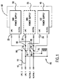
- Figure 1 is a schematic block diagram of the present invention live AC main selector for automatically selecting a live AC main in the event of a failure of a redundant AC main for a system having mismatched inputs and outputs.
- Figure 2 is a schematic block diagram of an alternate embodiment of Figure 1.
- Figure 3 is a schematic block diagram of an alternate embodiment of Figure 1 having two relay means.
- Figure 4 is a schematic block diagram of an alternate embodiment for a system having equal inputs and outputs.
- Figure 5 is a schematic block diagram of an alternate embodiment of Figure 4 having two relay means.
- Figure 1 is a schematic block diagram of the present invention live AC mains selector for a system 60 having mismatched inputs and outputs (i.e., three power supply inputs 20, 25, 30 vs. two AC main outputs 10, 15).
- mismatched inputs and outputs i.e., three power supply inputs 20, 25, 30 vs. two AC main outputs 10, 15.
- the invention will be discussed in the context of a disk storage system having redundant power supplies 45, 50, 55, and redundant AC mains 10 and 15, it is obvious that the invention is equally applicable to other electrical systems, subsystems, redundant systems, transfer circuits, receiving circuits, energy sources, or the like.
- Figures 1-3 are focused on a system which requires at least two power supplies 45, 50, for providing the necessary DC current to the system, and whereby a third power supply 55 is configured as a redundant supply in the event of a failure of one of the other two supplies 45, 50.
- a third power supply 55 is configured as a redundant supply in the event of a failure of one of the other two supplies 45, 50.
- Figures 4 and 5 depict the invention in connection with a system having two AC main outputs and two power supply inputs.
- the inputs and outputs are arbitrarily designated as first, second, third, etc., as examples only.
- first and second power supplies 45 and 50 provide the necessary DC current to disk storage system 60 (or other electrical system).
- the two AC mains 10 and 15 are feed circuits which provide voltage to the power supplies.
- First AC main 10 is tied to first power supply 45
- second AC main 15 is tied to second power supply 50. Both AC mains are not tied to a single power supply to avoid potential phase problems therebetween, since each main may originate from a different provider.
- Third power supply 55 is the redundant supply and, in the Figure, is also tied to first AC main 10 via switches 70.
- First and second supplies 45 and 50 are necessary for system operations, and third power supply 55 is a backup supply in the event either power supply 45 or 50 becomes inoperational.
- switching apparatus 65 provides a means for automatically selecting a live AC main in the event one AC main fails. Specifically, in the example shown, switching apparatus 65 is connected to first AC main 10. As such, when first AC main 10 is energized, switches 70 are pulled closed (into contact with terminals 75) by switching apparatus 65, thereby allowing third power supply 55 to be connected to first AC main 10. Thus, when both AC mains are energized, all three power supplies receive voltage for system 60.
- Switching apparatus 65 is any conventional relay in the art, such as an electro-mechanical double pole double throw switch, or it may be formed from solid state circuitry as obvious to those of ordinary skill in the art. In either case, the switching speed of relay 65 must be less than about one signal cycle of the AC main (i.e., about 20ms), so that continuity of the signal is maintained for the power supply after switching AC mains.
- first AC main 10 is de-energized (due to circuit breaker failure or other loss of AC for whatever reason)
- relay 65 is also de-energized, thereby causing switches 70 to automatically open and connect with second AC main 15 at terminals 80.
- first AC main 10 and first power supply 45 are inoperative with respect to system 60, but second AC main 15 and second and third power supplies 50 and 55 remain energized for supplying power to the system.
- first AC main continues to provide voltage to first power supply 45, and relay 65 remains energized through first AC main 10 and continues to provide voltage to third power supply 55 through switches 70.
- a novel aspect of this circuit is its ability to always supply AC current to the odd (third) power supply 55, regardless of a loss of either of the redundant AC mains 10 or 15.
- FIG. 2 is a schematic block diagram of an alternate embodiment of Figure 1. Like components retain like references throughout all the Figures. Output 20 of first AC main 10 is connected at terminals 90 of switch 70 rather than at terminals 75. As such, when AC main 10 is de-energized, this configuration provides power from second AC main 15 via relay 65 and switches 70 to all three power supplies 45, 50, 55, rather than just two power supplies. Thus, improved redundancy for system 60 is provided at the power supply level in the event first AC main 10 fails.
- Figure 3 depicts yet another embodiment providing even further redundancy improvement.
- second relay 95 is connected to second AC main 15 for providing a closed circuit to second power supply 50 through switches 100 when second AC main 15 is energized.
- Second relay 95 automatically breaks the circuit in the event second AC main 15 is de-energized, and immediately closes the circuit between first AC main 10 and second power supply 50 via switches 100.
- FIG. 4 a schematic block diagram is shown of the present invention in a system 85 having equal inputs 20, 25, and equal outputs 10, 15.
- This embodiment is applicable, for example, to an electrical system 85 that only requires one power supply, either 45 or 50, for DC current.
- the second supply is the redundant supply.
- relay 65 is de-energized thereby causing switches 70 to connect to second AC main 15 at terminals 80 for providing continued voltage to both power supplies 45 and 50.
- system 85 still retains redundancy of operational power supplies 45 and 50.
- Figure 5 depicts an alternate embodiment of Figure 4 employing a second relay 95.
- This configuration allows system 85 to retain energized both power supplies 45 and 50 in the event of failure of either AC main 10 or 15. The remaining live AC main is automatically selected by the respective relay for providing improved system reliability.
Landscapes
- Engineering & Computer Science (AREA)
- Power Engineering (AREA)
- Business, Economics & Management (AREA)
- Emergency Management (AREA)
- Stand-By Power Supply Arrangements (AREA)
- Power Sources (AREA)
Applications Claiming Priority (2)
| Application Number | Priority Date | Filing Date | Title |
|---|---|---|---|
| US08/719,219 US5917253A (en) | 1996-09-25 | 1996-09-25 | Live AC mains power selector for redundant systems |
| US719219 | 1996-09-25 |
Publications (1)
| Publication Number | Publication Date |
|---|---|
| EP0833424A2 true EP0833424A2 (de) | 1998-04-01 |
Family
ID=24889234
Family Applications (1)
| Application Number | Title | Priority Date | Filing Date |
|---|---|---|---|
| EP97105961A Withdrawn EP0833424A2 (de) | 1996-09-25 | 1997-04-10 | Netzspeisungsauswahlschaltung für eine stromführende Wechselstromleitung für redundante Systeme |
Country Status (3)
| Country | Link |
|---|---|
| US (1) | US5917253A (de) |
| EP (1) | EP0833424A2 (de) |
| JP (1) | JPH10111738A (de) |
Cited By (2)
| Publication number | Priority date | Publication date | Assignee | Title |
|---|---|---|---|---|
| US6621180B2 (en) * | 2001-04-20 | 2003-09-16 | International Business Machines Corporation | Method and system for maintaining full power during a power interruption in a multiple power supply system |
| EP1104591A4 (de) * | 1998-05-19 | 2005-02-09 | Sure Power Corp | Stromversorgungssystem |
Families Citing this family (22)
| Publication number | Priority date | Publication date | Assignee | Title |
|---|---|---|---|---|
| KR100262518B1 (ko) * | 1997-07-09 | 2000-08-01 | 윤종용 | 시스템상태를감지할수있는전원분배유닛 |
| US20040018158A1 (en) * | 1998-11-17 | 2004-01-29 | Tend Skin International, Inc. | Topical compositions including sunscreen compositions |
| US6553433B1 (en) * | 2000-04-12 | 2003-04-22 | Cheng-Chun Chang | IDE interface adapter |
| US6535369B1 (en) * | 2000-06-16 | 2003-03-18 | Teal Electronics Corporation | Adaptive surge suppressor |
| US6628013B2 (en) * | 2000-09-28 | 2003-09-30 | Intel Corporation | Redundant power subsystem |
| US6735704B1 (en) * | 2000-10-20 | 2004-05-11 | International Business Machines Corporation | Autonomic control of power subsystems in a redundant power system |
| US6833634B1 (en) * | 2001-01-04 | 2004-12-21 | 3Pardata, Inc. | Disk enclosure with multiple power domains |
| TW561676B (en) * | 2001-04-06 | 2003-11-11 | Delta Electronics Inc | Power supply device having an AC redundant function |
| US6791788B2 (en) * | 2001-06-29 | 2004-09-14 | Storage Technology Corporation | Segmented power strip for an automated robotic device and method for joining same |
| US6668991B2 (en) * | 2001-06-29 | 2003-12-30 | Sebastian Canaday | Redundant power supply system and method for an automated robotic device in a data storage system |
| US6751048B2 (en) * | 2001-06-29 | 2004-06-15 | Storage Technology Corporation | Power rail distribution system and method for an automated robotic device in a data storage system |
| US6751040B2 (en) * | 2001-06-29 | 2004-06-15 | Storagetechnology Corporation | Method for exchanging tape cartridges between automated tape cartridge libraries |
| US6798612B2 (en) * | 2001-06-29 | 2004-09-28 | Storage Technology Corporation | Power strip distribution system and method for an automated robotic device in a data storage system |
| US6760644B2 (en) * | 2001-06-29 | 2004-07-06 | Storage Technology Corporation | System and method for transmitting communication signals to an automated robotic device in a data storage system |
| US7287187B2 (en) * | 2001-10-15 | 2007-10-23 | Sun Microsystems, Inc. | Method and apparatus for supplying redundant power |
| US6747369B2 (en) * | 2002-08-22 | 2004-06-08 | Intel Corporation | Power system including redundant power supplies |
| US7005760B2 (en) | 2003-02-28 | 2006-02-28 | Kohler Co. | Automatic transfer switch system capable of governing the supply of power from more than two power sources to a load |
| US11316368B2 (en) | 2007-03-14 | 2022-04-26 | Zonit Structured Solutions, Llc | Premises power usage monitoring system |
| US8848722B2 (en) * | 2007-03-14 | 2014-09-30 | Zonit Structured Solutions, Llc | Data center network distribution system |
| EP2132759B1 (de) * | 2007-03-14 | 2016-11-02 | Zonit Structured Solutions, LLC | Schaltmodul für automatische übertragung |
| CA2681101C (en) * | 2007-03-14 | 2013-05-28 | Zonit Structured Solutions, Llc | Nema auto-switching duplex module |
| CA2719775C (en) * | 2008-03-26 | 2016-09-06 | Zonit Structured Solutions, Llc | Power distribution systems and methodology |
Family Cites Families (6)
| Publication number | Priority date | Publication date | Assignee | Title |
|---|---|---|---|---|
| US3818237A (en) * | 1972-08-14 | 1974-06-18 | Hughes Aircraft Co | Means for providing redundancy of key system components |
| US3835333A (en) * | 1973-03-19 | 1974-09-10 | M Balan | Redundant electrical system |
| US3949238A (en) * | 1975-01-13 | 1976-04-06 | Northern Electric Company, Limited | Distributed power switch for modular systems |
| JPH0112517Y2 (de) * | 1980-06-05 | 1989-04-12 | ||
| US4659942A (en) * | 1985-06-03 | 1987-04-21 | The Charles Stark Draper Laboratory, Inc. | Fault-tolerant power distribution system |
| US5638295A (en) * | 1995-08-08 | 1997-06-10 | Eaton Corporation | Transfer switch system with subnetwork |
-
1996
- 1996-09-25 US US08/719,219 patent/US5917253A/en not_active Expired - Fee Related
-
1997
- 1997-04-10 EP EP97105961A patent/EP0833424A2/de not_active Withdrawn
- 1997-09-24 JP JP9258114A patent/JPH10111738A/ja active Pending
Cited By (2)
| Publication number | Priority date | Publication date | Assignee | Title |
|---|---|---|---|---|
| EP1104591A4 (de) * | 1998-05-19 | 2005-02-09 | Sure Power Corp | Stromversorgungssystem |
| US6621180B2 (en) * | 2001-04-20 | 2003-09-16 | International Business Machines Corporation | Method and system for maintaining full power during a power interruption in a multiple power supply system |
Also Published As
| Publication number | Publication date |
|---|---|
| US5917253A (en) | 1999-06-29 |
| JPH10111738A (ja) | 1998-04-28 |
Similar Documents
| Publication | Publication Date | Title |
|---|---|---|
| EP0833424A2 (de) | Netzspeisungsauswahlschaltung für eine stromführende Wechselstromleitung für redundante Systeme | |
| US5994794A (en) | Methods and apparatus for providing protection to batteries in an uninterruptible power supply | |
| US5790394A (en) | Dual AC power supply input module | |
| US6031298A (en) | 2N redundant power system and method using cross-coupled AC power transfer | |
| US20090174261A1 (en) | Redundant power supply system | |
| US6011327A (en) | AC transfer switch | |
| US5530337A (en) | Battery cluster charger having a backup charging system | |
| JPH0150303B2 (de) | ||
| US20020153777A1 (en) | Method and system for maintaining full power during a power interruption in a multiple power supply system | |
| KR101821091B1 (ko) | 자동 부하 전환 계폐 시스템 및 이를 이용한 자동 부하 전환 계폐 방법 | |
| JP4102691B2 (ja) | 自動電源多重化装置 | |
| JPH03212132A (ja) | 二重化バックアップ電源の試験方法 | |
| JP2000102194A (ja) | 入力二重化高性能電源システム | |
| JP3927907B2 (ja) | ロータリダイナミックシステム電力分配器 | |
| JPH0441740Y2 (de) | ||
| JPH05233001A (ja) | 停電時のバックアップ蓄電池回路 | |
| JPS60118028A (ja) | 監視装置用電源 | |
| SU1149351A1 (ru) | Устройство дл резервировани источников электропитани | |
| JP3045748B2 (ja) | 電源切り換え方法 | |
| JPS62285638A (ja) | インバ−タ出力切換回路 | |
| JP2766690B2 (ja) | バッテリー切断方式 | |
| JP2000217274A (ja) | 無停電電源システム | |
| GB2338844A (en) | Interface for by-passing a failed uninterruptible power supply | |
| JPS61207138A (ja) | 無停電定電圧定周波電源装置 | |
| SU656152A1 (ru) | Устройство дл разгрузки района электрической сети |
Legal Events
| Date | Code | Title | Description |
|---|---|---|---|
| PUAI | Public reference made under article 153(3) epc to a published international application that has entered the european phase |
Free format text: ORIGINAL CODE: 0009012 |
|
| AK | Designated contracting states |
Kind code of ref document: A2 Designated state(s): DE FR GB |
|
| STAA | Information on the status of an ep patent application or granted ep patent |
Free format text: STATUS: THE APPLICATION HAS BEEN WITHDRAWN |
|
| 18W | Application withdrawn |
Withdrawal date: 19990225 |