EP0833302A2 - Schallfeldwiedergabegerät - Google Patents
Schallfeldwiedergabegerät Download PDFInfo
- Publication number
- EP0833302A2 EP0833302A2 EP97116818A EP97116818A EP0833302A2 EP 0833302 A2 EP0833302 A2 EP 0833302A2 EP 97116818 A EP97116818 A EP 97116818A EP 97116818 A EP97116818 A EP 97116818A EP 0833302 A2 EP0833302 A2 EP 0833302A2
- Authority
- EP
- European Patent Office
- Prior art keywords
- crosstalk
- sound field
- listener
- reproducing
- cancelling
- Prior art date
- Legal status (The legal status is an assumption and is not a legal conclusion. Google has not performed a legal analysis and makes no representation as to the accuracy of the status listed.)
- Withdrawn
Links
Images


Classifications
-
- H—ELECTRICITY
- H04—ELECTRIC COMMUNICATION TECHNIQUE
- H04S—STEREOPHONIC SYSTEMS
- H04S1/00—Two-channel systems
- H04S1/007—Two-channel systems in which the audio signals are in digital form
Definitions
- the present invention relates to a sound field reproducing device capable of faithfully reproducing an original sound field that existed during recording of sound.
- Transaural systems are among conventionally-known means which, using speakers, faithfully reproduce, close to listener's ears, sound pressure in a sound field that existed during recording of sound (hereinafter referred to as an "original sound field").
- original sound field a sound field that existed during recording of sound
- a sound field reproducing device that employs crosstalk cancelling circuitry.
- sounds recorded in two channels by use of a dummy head are to be reproduced via right and left speakers in a given sound field (hereinafter referred to as a "reproducing sound filed”), it is desirable that the sound output from, for example, the right speaker should reach only the listener's right ear.
- crosstalk could be a significant obstacle in faithfully reproducing recorded sounds in the reproducing sound field.
- the sound output from the left speaker is also affected by similar spatial sound propagation characteristics in the reproducing sound field. It is desirable that the sounds output from the speakers be not affected by such characteristics.
- Known crosstalk cancelling circuitry includes a filter having a filter characteristic to eliminate the influences of the spatial sound propagation characteristics in the reproducing sound field, where signals of each sound recorded by use of a dummy head are reproduced after having been processed by the filter.
- filter characteristic there has been employed one calculated primarily for a standard stereo-reproducing speaker arrangement where the right and left speakers are placed in a horizontal plane at ⁇ 30° with respect to a listener.
- the present invention provides a sound field reproducing device for reproducing an original sound field in a reproducing sound field, which comprises a plurality of crosstalk cancelling sections to cancel crosstalk that occurs at a listening position of a listener when two-channel input sound signals are to be reproduced via a pair of right and left speakers placed in front of the listener.
- the crosstalk cancelling sections are provided in corresponding relations to a plurality of possible arrangements of the speakers relative to the listener, and each of the crosstalk cancelling sections is set to be able to most efficiently cancel the crosstalk when the speakers are in one of the arrangements corresponding to the crosstalk cancelling section.
- the device further comprises a selector section which selects any one of the crosstalk cancelling sections and allows the two-channel input sound signals to be processed by the selected crosstalk cancelling section.
- a sound field reproducing device for reproducing an original sound field in a reproducing sound field, which comprises a crosstalk cancelling section including a plurality of filters having respective filter characteristics determined by coefficient data supplied from outside the sound field reproducing device.
- the crosstalk cancelling section allows two-channel input sound signals to be processed by the filters to thereby cancel crosstalk that occurs at a listening position of a listener when the input sound signals are to be reproduced via a pair of right and left speakers placed in front of the listener.
- the device also comprises a storage section having prestored therein, in corresponding relations to a plurality of possible arrangements of the speakers relative to the listener, plural sets of coefficient data to be supplied to the filters.
- Each of the sets of coefficient data sets the filters to respective filter characteristics that allow the filters to most efficiently cancel the crosstalk when the speakers are in one of the arrangements corresponding to the set.
- the device further comprises a data selector section which selects one of the sets of coefficient data and supplies the coefficient data of the selected set to the respective filters.
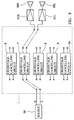
- Fig. 1 there is shown exemplary arrangements of right and left speakers relative to a listener to which is applied a sound field reproducing device according to an embodiment of the present invention.
- the right and left speakers R and L can be variably placed, symmetrically about a "0° position" right in front of the listener LM, at a plurality of different positions; more specifically, the right speaker 30R can be variably set at any one of position A (+5° position), position B (+15° position), position C (+30° position), position D (+45° position) and position E (+60° position), while the left speaker 30L can be variably set at any of position A' (-5° position), position B' (-15° position), position C' (-30° position), position D' (-45° position) and position E' (-60° position).
- the plus sign (+) is attached to the placement angles of the right speaker R
- the minus sign (-) is attached to the placement angles of the left speaker L.
- the optimum filter characteristic of crosstalk cancelling circuitry that can most efficiently cancel undesirable crosstalk substantially differ among the above-noted five possible speaker arrangements.
- a plurality of crosstalk cancelling circuits are provided in corresponding relations to the possible speaker arrangements A, A' - E, E' and each of these crosstalk cancelling circuits is provided with filters each having an optimum filter characteristic depending on the corresponding speaker arrangement.
- the crosstalk cancelling circuit to be used is switched from one to another, depending on the arrangement of the speakers 30R and 30L selected by a user for desired reproduction.
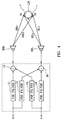
- Reference numeral 1 denotes the body of the sound field reproducing device according to the present embodiment, to which a sound signal source 20 supplies a right signal R and a left sound signal L (hereinafter, referred to simply as "signal R and signal L").
- the body 1 of the sound field reproducing device processes the supplied signals R and L so that crosstalk is cancelled most effectively depending on current positions or actual user-selected arrangement of the speakers 30R and 30L, and then it outputs the processed sound signals to power amplifiers 31R and 31L, respectively.
- the signals amplified by the power amplifiers 31R and 31L are audibly reproduced via the right and left speakers 30R and 30L.
- the signals R and L are signals of a sound recorded in two channels using a dummy head (not shown).
- reference numeral 2 denotes a plug connector for coupling electric power from a power supply to the device body 1, and 4 is a power supply switch of the sound field reproducing device.
- Reference numeral 3 denotes a neon tube that is illuminated by turning on the power supply switch 4.
- Reference numeral 5 is a rotary switch having five operating positions: “ ⁇ 5° “; “ ⁇ 15° “; “ ⁇ 30° “; “ ⁇ 45° “; and " ⁇ 60° “. The user can set a pointer mark (" ⁇ ") 5a of the rotary switch 5 to any one of the five operating positions depending on a detected user-selected arrangement of the right and left speakers 30R and 30L.
- FIG. 3 a block diagram of Fig. 3, in which the above-mentioned body 1 of the device is shown within a dotted-line block.
- reference numerals 6 to 10 denote crosstalk cancelling circuits.
- the crosstalk cancelling circuit 6 has a filter characteristic such that crosstalk is cancelled most efficiently when the speakers R and L are at positions A and A'.
- the other crosstalk cancelling circuits 7 to 10 have respective filter characteristics such that crosstalk is cancelled most efficiently when the speakers R and L are at positions B and B', C and C', D and D', and E and E', respectively.
- signals R and L output output from the sound signal source 20 are supplied to a specific one of the above-mentioned crosstalk cancelling circuits 6 to 10, and resultant output signals from the specific crosstalk cancelling circuit are then passed to the power amplifiers 31R and 31L, respectively.
- a signal route is selected which allows the signals R and L to be processed by any one of the crosstalk cancelling circuits 6 to 10 that has a filter characteristic capable of cancelling unwanted crosstalk with maximum efficiency.
- Fig. 3 shows an example where the pointer mark 5a of the rotary switch 5 is set to point to the " ⁇ 15° " operating position.
- signals R and L output output from the sound signal source 20 are supplied to the crosstalk cancelling circuit 7, where the signals R and L are subjected to processing such that crosstalk is cancelled most efficiently while the right and left speakers R and L are at positions "B" and "B' ", respectively.
- the thus-processed signals R and L are then passed to the power amplifiers 31R and 31L to be reproduced as audible sounds via the right and left speakers 30R and 30L, respectively.
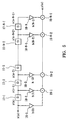
- a dotted-line block represents the construction of one of the crosstalk cancelling circuits 6 to 10.
- the illustrated construction is the same for all the circuits 6 to 10.
- reference numerals 11 to 14 denote FIR (Finite Impulse Response) filters.
- the signal R from the sound signal source 20 is supplied to the FIR filters 11 and 12, while the signal L from the source is supplied to the FIR filters 13 and 14.
- Each of the FIR filters 11 to 14 has such a filter characteristic that cancels out sound propagation characteristics in a reproducing sound field for the corresponding placement positions of the right and left speakers 30R and 30L.
- Reference numerals 15 to 16 denote adders.
- the adder 15 adds together output signals from the FIR filters 11 and 13 and supplies the addition result to the right speaker 30R via the power amplifier 31R (not shown in Fig. 4), while the adder 16 adds together output signals from the FIR filters 12 and 14 and supplies the addition result to the left speaker 30L via the power amplifier 31L (not shown in Fig. 4).
- Sr Sl HRr HRl HLr HLl R L
- HRr represents a speaker-to-head propagation function of sound travelling from the right speaker 30R to the right ear r of the listener LM
- HRl represents a speaker-to-head propagation function of sound travelling from the right speaker 30R to the left ear l of the listener LM
- HLr represents a speaker-to-head propagation function of sound travelling from the left speaker 30L to the right ear r of the listener LM
- HLl represents a speaker-to-head propagation function of sound travelling from the left speaker 30L to the left ear l of the listener LM.
- reference numerals 17-1 to 17-N-1 denote unit time delay elements connected in series, each of which delays, by one sampling period, signal x(n) (signal R or signal L) that is output from the sound signal source 20 every sampling period; here, "n” denotes a time in sampling periods.
- Reference numerals 18-1 to 18-N denote multipliers, which multiply input signal x(n) and output signals from the unit time delay elements 17-1 to 17-N-1 by predetermined multiplication coefficients h(0) and h(1) to h(N-1), respectively.
- reference numerals 19-1 to 19-N-1 denote adders, which sequentially add together respective output signals from the multipliers 18-1 to 18-N.
- time-domain input signal x(n), output signal y(n) and multiplication coefficient h(n) and among frequency-domain input signal X(n), output signal Y(n) and multiplication coefficient H(n) may be represented by the following expressions based on 1) the discrete Fourier transform (DFT) and 2) the inverse discrete Fourier transform (IDFT):
- the number of the unit time delay elements and the multiplication coefficients of the multipliers are determined on the basis of actual measurements of individual impulse responses of sound travelling from the right and left speakers 30R and 30L to the listener's right and left years.
- a plurality of crosstalk cancelling circuits are provided which have filter characteristics corresponding to a plurality of possible arrangements of the right and left speakers 30R and 30L of Fig. 1 relative to the listener, and any one of the crosstalk cancelling circuits is selected depending on an actual user-selected arrangement of the speakers so that signals R and L are processed by the selected circuit.
- only one crosstalk cancelling circuit may be provided.
- plural sets of coefficient data to be used in the individual FIR filters may be stored in a memory, in corresponding relations to the possible arrangements of the speakers, so that one of the sets of coefficient data is selected depending on an actual user-selected arrangement of the speakers and the individual coefficient data of the selected set are supplied to the respective FIR filters.
- the sound field reproducing device arranged in accordance with one aspect of the present invention can select one of the crosstalk cancelling circuits that is set to most efficiently cancel unwanted crosstalk in an actual user-selected arrangement of the speakers.
- a single sound field reproducing device thus arranged always permits optimum crosstalk cancellation in a variety of possible speaker arrangements.
- the sound field reproducing device arranged in accordance with another aspect of the present invention always permits optimum crosstalk cancellation in a variety of possible speaker arrangements with only a single crosstalk cancelling circuit by just supplying the filters with a different set of coefficient data depending on an actual user-selected arrangement of the speakers, without a need to provide a plurality of crosstalk cancelling circuits in corresponding relations to a plurality of possible arrangements of the speakers.
- the invention relates to a sound field reproducing device for reproducing an original sound field in a reproducing sound field, which comprises:
Applications Claiming Priority (2)
| Application Number | Priority Date | Filing Date | Title |
|---|---|---|---|
| JP8257192A JPH10108300A (ja) | 1996-09-27 | 1996-09-27 | 音場再生装置 |
| JP257192/96 | 1996-09-27 |
Publications (2)
| Publication Number | Publication Date |
|---|---|
| EP0833302A2 true EP0833302A2 (de) | 1998-04-01 |
| EP0833302A3 EP0833302A3 (de) | 1999-03-10 |
Family
ID=17302965
Family Applications (1)
| Application Number | Title | Priority Date | Filing Date |
|---|---|---|---|
| EP97116818A Withdrawn EP0833302A3 (de) | 1996-09-27 | 1997-09-26 | Schallfeldwiedergabegerät |
Country Status (2)
| Country | Link |
|---|---|
| EP (1) | EP0833302A3 (de) |
| JP (1) | JPH10108300A (de) |
Cited By (4)
| Publication number | Priority date | Publication date | Assignee | Title |
|---|---|---|---|---|
| EP0975201A2 (de) * | 1998-07-24 | 2000-01-26 | Central Research Laboratories Limited | Verfahren zur Mehrkanal-Tonsignalverarbeitung |
| WO2002028064A1 (fr) * | 2000-09-27 | 2002-04-04 | Nec Corporation | Systeme et procede de reproduction de sons pour dispositif terminal portable |
| EP1699263A1 (de) * | 2003-12-24 | 2006-09-06 | Mitsubishi Denki Kabushiki Kaisha | Akustisches signalwiedergabeverfahren |
| WO2009127515A1 (en) * | 2008-04-16 | 2009-10-22 | Telefonaktiebolaget Lm Ericsson (Publ) | Apparatus and method for producing 3d audio in systems with closely spaced speakers |
Families Citing this family (2)
| Publication number | Priority date | Publication date | Assignee | Title |
|---|---|---|---|---|
| KR100899162B1 (ko) * | 2007-11-30 | 2009-05-27 | (재)경기대진테크노파크 | 차동 증폭 회로 및 그를 갖는 무선 스피커 장치 |
| US20120294446A1 (en) * | 2011-05-16 | 2012-11-22 | Qualcomm Incorporated | Blind source separation based spatial filtering |
Citations (4)
| Publication number | Priority date | Publication date | Assignee | Title |
|---|---|---|---|---|
| EP0357402A2 (de) * | 1988-09-02 | 1990-03-07 | Q Sound Ltd | Verfahren und Vorrichtung zur Schallbilderzeugung |
| US5333200A (en) * | 1987-10-15 | 1994-07-26 | Cooper Duane H | Head diffraction compensated stereo system with loud speaker array |
| US5404406A (en) * | 1992-11-30 | 1995-04-04 | Victor Company Of Japan, Ltd. | Method for controlling localization of sound image |
| EP0666556A2 (de) * | 1994-02-04 | 1995-08-09 | Matsushita Electric Industrial Co., Ltd. | Schallfeldkontrollegerät und Kontrolleverfahren |
-
1996
- 1996-09-27 JP JP8257192A patent/JPH10108300A/ja active Pending
-
1997
- 1997-09-26 EP EP97116818A patent/EP0833302A3/de not_active Withdrawn
Patent Citations (4)
| Publication number | Priority date | Publication date | Assignee | Title |
|---|---|---|---|---|
| US5333200A (en) * | 1987-10-15 | 1994-07-26 | Cooper Duane H | Head diffraction compensated stereo system with loud speaker array |
| EP0357402A2 (de) * | 1988-09-02 | 1990-03-07 | Q Sound Ltd | Verfahren und Vorrichtung zur Schallbilderzeugung |
| US5404406A (en) * | 1992-11-30 | 1995-04-04 | Victor Company Of Japan, Ltd. | Method for controlling localization of sound image |
| EP0666556A2 (de) * | 1994-02-04 | 1995-08-09 | Matsushita Electric Industrial Co., Ltd. | Schallfeldkontrollegerät und Kontrolleverfahren |
Cited By (9)
| Publication number | Priority date | Publication date | Assignee | Title |
|---|---|---|---|---|
| EP0975201A2 (de) * | 1998-07-24 | 2000-01-26 | Central Research Laboratories Limited | Verfahren zur Mehrkanal-Tonsignalverarbeitung |
| GB2340005A (en) * | 1998-07-24 | 2000-02-09 | Central Research Lab Ltd | Crosstalk compensation in a plural channel audio signal |
| GB2340005B (en) * | 1998-07-24 | 2003-03-19 | Central Research Lab Ltd | A method of processing a plural channel audio signal |
| EP0975201A3 (de) * | 1998-07-24 | 2005-06-08 | Creative Technology Ltd. | Verfahren zur Mehrkanal-Tonsignalverarbeitung |
| WO2002028064A1 (fr) * | 2000-09-27 | 2002-04-04 | Nec Corporation | Systeme et procede de reproduction de sons pour dispositif terminal portable |
| EP1699263A1 (de) * | 2003-12-24 | 2006-09-06 | Mitsubishi Denki Kabushiki Kaisha | Akustisches signalwiedergabeverfahren |
| EP1699263A4 (de) * | 2003-12-24 | 2007-08-08 | Mitsubishi Electric Corp | Akustisches signalwiedergabeverfahren |
| WO2009127515A1 (en) * | 2008-04-16 | 2009-10-22 | Telefonaktiebolaget Lm Ericsson (Publ) | Apparatus and method for producing 3d audio in systems with closely spaced speakers |
| US8295498B2 (en) | 2008-04-16 | 2012-10-23 | Telefonaktiebolaget Lm Ericsson (Publ) | Apparatus and method for producing 3D audio in systems with closely spaced speakers |
Also Published As
| Publication number | Publication date |
|---|---|
| EP0833302A3 (de) | 1999-03-10 |
| JPH10108300A (ja) | 1998-04-24 |
Similar Documents
| Publication | Publication Date | Title |
|---|---|---|
| JP3565908B2 (ja) | 立体感および/または音響特性感のシミュレーション方法および装置 | |
| US6385320B1 (en) | Surround signal processing apparatus and method | |
| KR101184641B1 (ko) | 오디오 신호 처리 시스템 및 그 방법 | |
| EP0865227B1 (de) | Schallfeldsteuerungssystem | |
| KR0175515B1 (ko) | 테이블 조사 방식의 스테레오 구현 장치와 방법 | |
| US5889867A (en) | Stereophonic Reformatter | |
| US6970569B1 (en) | Audio processing apparatus and audio reproducing method | |
| US20070027945A1 (en) | Audio frequency response processing system | |
| JPH10509565A (ja) | 録音及び再生システム | |
| US4888804A (en) | Sound reproduction system | |
| US5844993A (en) | Surround signal processing apparatus | |
| JP2008502200A (ja) | ワイドステレオ再生方法及びその装置 | |
| JPH09327099A (ja) | 音響再生装置 | |
| JP4023842B2 (ja) | ディジタルフィルタ及び音響再生装置 | |
| EP0833302A2 (de) | Schallfeldwiedergabegerät | |
| JP3219752B2 (ja) | 疑似ステレオ化装置 | |
| KR100630436B1 (ko) | 디지털 신호처리회로와 이것을 사용하는 오디오 재생장치 | |
| CN100444695C (zh) | 一种实现串音消除的方法及滤波器生成装置和播放装置 | |
| US6370256B1 (en) | Time processed head related transfer functions in a headphone spatialization system | |
| JP3374425B2 (ja) | 音響装置 | |
| JP3500746B2 (ja) | 音像定位装置及びフィルタ設定方法 | |
| KR19980031979A (ko) | 머리전달 함수를 이용한 두 채널에서의 3차원 음장 재생방법 및 장치 | |
| JPS6013640B2 (ja) | ステレオ再生方式 | |
| JPH05207597A (ja) | 音場再生装置 | |
| JP2945232B2 (ja) | 音像定位制御装置 |
Legal Events
| Date | Code | Title | Description |
|---|---|---|---|
| PUAI | Public reference made under article 153(3) epc to a published international application that has entered the european phase |
Free format text: ORIGINAL CODE: 0009012 |
|
| AK | Designated contracting states |
Kind code of ref document: A2 Designated state(s): DE FR GB |
|
| AX | Request for extension of the european patent |
Free format text: AL;LT;LV;RO;SI |
|
| PUAL | Search report despatched |
Free format text: ORIGINAL CODE: 0009013 |
|
| AK | Designated contracting states |
Kind code of ref document: A3 Designated state(s): AT BE CH DE DK ES FI FR GB GR IE IT LI LU MC NL PT SE |
|
| AX | Request for extension of the european patent |
Free format text: AL;LT;LV;RO;SI |
|
| 17P | Request for examination filed |
Effective date: 19990831 |
|
| AKX | Designation fees paid |
Free format text: DE FR GB |
|
| 17Q | First examination report despatched |
Effective date: 20011018 |
|
| STAA | Information on the status of an ep patent application or granted ep patent |
Free format text: STATUS: THE APPLICATION IS DEEMED TO BE WITHDRAWN |
|
| 18D | Application deemed to be withdrawn |
Effective date: 20020430 |