EP0833302A2 - Sound field reproducing device - Google Patents
Sound field reproducing device Download PDFInfo
- Publication number
- EP0833302A2 EP0833302A2 EP97116818A EP97116818A EP0833302A2 EP 0833302 A2 EP0833302 A2 EP 0833302A2 EP 97116818 A EP97116818 A EP 97116818A EP 97116818 A EP97116818 A EP 97116818A EP 0833302 A2 EP0833302 A2 EP 0833302A2
- Authority
- EP
- European Patent Office
- Prior art keywords
- crosstalk
- sound field
- listener
- reproducing
- cancelling
- Prior art date
- Legal status (The legal status is an assumption and is not a legal conclusion. Google has not performed a legal analysis and makes no representation as to the accuracy of the status listed.)
- Withdrawn
Links
Images


Classifications
-
- H—ELECTRICITY
- H04—ELECTRIC COMMUNICATION TECHNIQUE
- H04S—STEREOPHONIC SYSTEMS
- H04S1/00—Two-channel systems
- H04S1/007—Two-channel systems in which the audio signals are in digital form
Abstract
Description
Claims (4)
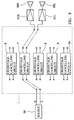
- A sound field reproducing device for reproducing an original sound field in a reproducing sound field, which comprises:a plurality of crosstalk cancelling sections that cancel crosstalk occurring at a listening position of a listener when two-channel input sound signals are to be reproduced via a pair of right and left speakers placed in front of the listener, said crosstalk cancelling sections being provided in corresponding relations to a plurality of possible arrangements of said speakers relative to the listener, each of said crosstalk cancelling sections being set to be able to most efficiently cancel the crosstalk when said speakers are in one of the arrangements corresponding to said crosstalk cancelling section; anda selector section that selects any one of said crosstalk cancelling sections and allows the two-channel input sound signals to be processed by the selected crosstalk cancelling section.
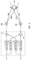
- A sound field reproducing device for reproducing an original sound field in a reproducing sound field, which comprises:a crosstalk cancelling section including a plurality of filters having respective filter characteristics determined by coefficient data supplied from outside said sound field reproducing device, said crosstalk cancelling section allowing two-channel input sound signals to be processed by said filters to thereby cancel crosstalk that occurs at a listening position of a listener when the input sound signals are to be reproduced via a pair of right and left speakers placed in front of the listener; anda storage section having prestored therein, in corresponding relations to a plurality of possible arrangements of said speakers relative to the listener, plural sets of coefficient data to be supplied to said filters, each of the sets of coefficient data setting said filters to respective filter characteristics that allow said filters to most efficiently cancel the crosstalk when said speakers are in one of the arrangements corresponding to the set; anda data selector section that selects one of the sets of coefficient data and supplies the coefficient data of the selected set to respective ones of said filters.
- A sound field reproducing method for reproducing an original sound field in a reproducing sound field, which comprises steps of:selecting any one a plurality of crosstalk cancelling sections that cancel corsstalk occurring at a listening position of a listener when two-channel input sound singals are to be reproduced via a pair of right and left speakers placed in front of the listener, said crosstalk cancelling sections being provided in corresponding relations to a plurality of possible arrangments of said crosstalk cancelling sections being set to be able to most efficiently cancel the crosstalk when said speakers are in one of the arrangements corresponding to said crosstalk cancelling section: andallowing the two-channel input sound signals to be processed by the selected crosstalk cancelling section.
- A sound field reproducing device for reproducing an original sound field in a reproducing sound field, which comprises:a plurality of crosstalk cancelling sections; anda selector section that selects any one of said crosstalk cancelling sections.
Applications Claiming Priority (2)
| Application Number | Priority Date | Filing Date | Title |
|---|---|---|---|
| JP257192/96 | 1996-09-27 | ||
| JP8257192A JPH10108300A (en) | 1996-09-27 | 1996-09-27 | Sound field reproduction device |
Publications (2)
| Publication Number | Publication Date |
|---|---|
| EP0833302A2 true EP0833302A2 (en) | 1998-04-01 |
| EP0833302A3 EP0833302A3 (en) | 1999-03-10 |
Family
ID=17302965
Family Applications (1)
| Application Number | Title | Priority Date | Filing Date |
|---|---|---|---|
| EP97116818A Withdrawn EP0833302A3 (en) | 1996-09-27 | 1997-09-26 | Sound field reproducing device |
Country Status (2)
| Country | Link |
|---|---|
| EP (1) | EP0833302A3 (en) |
| JP (1) | JPH10108300A (en) |
Cited By (4)
| Publication number | Priority date | Publication date | Assignee | Title |
|---|---|---|---|---|
| EP0975201A2 (en) * | 1998-07-24 | 2000-01-26 | Central Research Laboratories Limited | A method of processing a plural channel audio signal |
| WO2002028064A1 (en) * | 2000-09-27 | 2002-04-04 | Nec Corporation | Sound reproducing system and method for portable terminal device |
| EP1699263A1 (en) * | 2003-12-24 | 2006-09-06 | Mitsubishi Denki Kabushiki Kaisha | Acoustic signal reproducing method |
| WO2009127515A1 (en) * | 2008-04-16 | 2009-10-22 | Telefonaktiebolaget Lm Ericsson (Publ) | Apparatus and method for producing 3d audio in systems with closely spaced speakers |
Families Citing this family (2)
| Publication number | Priority date | Publication date | Assignee | Title |
|---|---|---|---|---|
| KR100899162B1 (en) * | 2007-11-30 | 2009-05-27 | (재)경기대진테크노파크 | Differential amplifier circuit and wireless speaker apparatus having it |
| US20120294446A1 (en) * | 2011-05-16 | 2012-11-22 | Qualcomm Incorporated | Blind source separation based spatial filtering |
Citations (4)
| Publication number | Priority date | Publication date | Assignee | Title |
|---|---|---|---|---|
| EP0357402A2 (en) * | 1988-09-02 | 1990-03-07 | Q Sound Ltd | Sound imaging method and apparatus |
| US5333200A (en) * | 1987-10-15 | 1994-07-26 | Cooper Duane H | Head diffraction compensated stereo system with loud speaker array |
| US5404406A (en) * | 1992-11-30 | 1995-04-04 | Victor Company Of Japan, Ltd. | Method for controlling localization of sound image |
| EP0666556A2 (en) * | 1994-02-04 | 1995-08-09 | Matsushita Electric Industrial Co., Ltd. | Sound field controller and control method |
-
1996
- 1996-09-27 JP JP8257192A patent/JPH10108300A/en active Pending
-
1997
- 1997-09-26 EP EP97116818A patent/EP0833302A3/en not_active Withdrawn
Patent Citations (4)
| Publication number | Priority date | Publication date | Assignee | Title |
|---|---|---|---|---|
| US5333200A (en) * | 1987-10-15 | 1994-07-26 | Cooper Duane H | Head diffraction compensated stereo system with loud speaker array |
| EP0357402A2 (en) * | 1988-09-02 | 1990-03-07 | Q Sound Ltd | Sound imaging method and apparatus |
| US5404406A (en) * | 1992-11-30 | 1995-04-04 | Victor Company Of Japan, Ltd. | Method for controlling localization of sound image |
| EP0666556A2 (en) * | 1994-02-04 | 1995-08-09 | Matsushita Electric Industrial Co., Ltd. | Sound field controller and control method |
Cited By (9)
| Publication number | Priority date | Publication date | Assignee | Title |
|---|---|---|---|---|
| EP0975201A2 (en) * | 1998-07-24 | 2000-01-26 | Central Research Laboratories Limited | A method of processing a plural channel audio signal |
| GB2340005A (en) * | 1998-07-24 | 2000-02-09 | Central Research Lab Ltd | Crosstalk compensation in a plural channel audio signal |
| GB2340005B (en) * | 1998-07-24 | 2003-03-19 | Central Research Lab Ltd | A method of processing a plural channel audio signal |
| EP0975201A3 (en) * | 1998-07-24 | 2005-06-08 | Creative Technology Ltd. | A method of processing a plural channel audio signal |
| WO2002028064A1 (en) * | 2000-09-27 | 2002-04-04 | Nec Corporation | Sound reproducing system and method for portable terminal device |
| EP1699263A1 (en) * | 2003-12-24 | 2006-09-06 | Mitsubishi Denki Kabushiki Kaisha | Acoustic signal reproducing method |
| EP1699263A4 (en) * | 2003-12-24 | 2007-08-08 | Mitsubishi Electric Corp | Acoustic signal reproducing method |
| WO2009127515A1 (en) * | 2008-04-16 | 2009-10-22 | Telefonaktiebolaget Lm Ericsson (Publ) | Apparatus and method for producing 3d audio in systems with closely spaced speakers |
| US8295498B2 (en) | 2008-04-16 | 2012-10-23 | Telefonaktiebolaget Lm Ericsson (Publ) | Apparatus and method for producing 3D audio in systems with closely spaced speakers |
Also Published As
| Publication number | Publication date |
|---|---|
| EP0833302A3 (en) | 1999-03-10 |
| JPH10108300A (en) | 1998-04-24 |
Similar Documents
| Publication | Publication Date | Title |
|---|---|---|
| JP3565908B2 (en) | Simulation method and apparatus for three-dimensional effect and / or acoustic characteristic effect | |
| KR101184641B1 (en) | Audio signal processing system and method | |
| KR0175515B1 (en) | Apparatus and Method for Implementing Table Survey Stereo | |
| US5889867A (en) | Stereophonic Reformatter | |
| US6970569B1 (en) | Audio processing apparatus and audio reproducing method | |
| US20070027945A1 (en) | Audio frequency response processing system | |
| JPH10509565A (en) | Recording and playback system | |
| US4888804A (en) | Sound reproduction system | |
| US5844993A (en) | Surround signal processing apparatus | |
| JP2008502200A (en) | Wide stereo playback method and apparatus | |
| JPH09327099A (en) | Acoustic reproduction device | |
| JP4023842B2 (en) | Digital filter and sound reproduction device | |
| EP0833302A2 (en) | Sound field reproducing device | |
| JP3219752B2 (en) | Pseudo-stereo device | |
| KR100630436B1 (en) | Digital signal processing circuit and audio reproducing device using it | |
| CN100444695C (en) | A method for realizing crosstalk elimination and filter generation and playing device | |
| US6370256B1 (en) | Time processed head related transfer functions in a headphone spatialization system | |
| JP3374425B2 (en) | Sound equipment | |
| JP3500746B2 (en) | Sound image localization device and filter setting method | |
| JPS6013640B2 (en) | Stereo playback method | |
| JPH05207597A (en) | Sound field reproduction device | |
| JP2945232B2 (en) | Sound image localization control device | |
| JPH0746700A (en) | Signal processor and sound field processor using same | |
| JP2003111198A (en) | Voice signal processing method and voice reproducing system | |
| JP2006323395A (en) | Signal processing apparatus and sound reproducing apparatus |
Legal Events
| Date | Code | Title | Description |
|---|---|---|---|
| PUAI | Public reference made under article 153(3) epc to a published international application that has entered the european phase |
Free format text: ORIGINAL CODE: 0009012 |
|
| AK | Designated contracting states |
Kind code of ref document: A2 Designated state(s): DE FR GB |
|
| AX | Request for extension of the european patent |
Free format text: AL;LT;LV;RO;SI |
|
| PUAL | Search report despatched |
Free format text: ORIGINAL CODE: 0009013 |
|
| AK | Designated contracting states |
Kind code of ref document: A3 Designated state(s): AT BE CH DE DK ES FI FR GB GR IE IT LI LU MC NL PT SE |
|
| AX | Request for extension of the european patent |
Free format text: AL;LT;LV;RO;SI |
|
| 17P | Request for examination filed |
Effective date: 19990831 |
|
| AKX | Designation fees paid |
Free format text: DE FR GB |
|
| 17Q | First examination report despatched |
Effective date: 20011018 |
|
| STAA | Information on the status of an ep patent application or granted ep patent |
Free format text: STATUS: THE APPLICATION IS DEEMED TO BE WITHDRAWN |
|
| 18D | Application deemed to be withdrawn |
Effective date: 20020430 |