EP0833047B1 - Pressure balanced synchronizing nozzle - Google Patents
Pressure balanced synchronizing nozzle Download PDFInfo
- Publication number
- EP0833047B1 EP0833047B1 EP97307622A EP97307622A EP0833047B1 EP 0833047 B1 EP0833047 B1 EP 0833047B1 EP 97307622 A EP97307622 A EP 97307622A EP 97307622 A EP97307622 A EP 97307622A EP 0833047 B1 EP0833047 B1 EP 0833047B1
- Authority
- EP
- European Patent Office
- Prior art keywords
- nozzle
- synchronization ring
- flaps
- convergent
- divergent
- Prior art date
- Legal status (The legal status is an assumption and is not a legal conclusion. Google has not performed a legal analysis and makes no representation as to the accuracy of the status listed.)
- Expired - Lifetime
Links
- 230000003068 static effect Effects 0.000 claims description 23
- 238000001816 cooling Methods 0.000 claims description 9
- 230000008859 change Effects 0.000 claims description 6
- 238000005096 rolling process Methods 0.000 claims 1
- 239000000446 fuel Substances 0.000 description 9
- 239000007789 gas Substances 0.000 description 8
- 238000007789 sealing Methods 0.000 description 7
- 238000010276 construction Methods 0.000 description 4
- 230000009467 reduction Effects 0.000 description 3
- 230000002829 reductive effect Effects 0.000 description 3
- 238000009434 installation Methods 0.000 description 2
- 230000036961 partial effect Effects 0.000 description 2
- 230000004044 response Effects 0.000 description 2
- 230000009471 action Effects 0.000 description 1
- 230000002411 adverse Effects 0.000 description 1
- 230000009977 dual effect Effects 0.000 description 1
- 239000012530 fluid Substances 0.000 description 1
- 230000001771 impaired effect Effects 0.000 description 1
- 238000004519 manufacturing process Methods 0.000 description 1
- 230000007246 mechanism Effects 0.000 description 1
- 238000011144 upstream manufacturing Methods 0.000 description 1
- 230000003313 weakening effect Effects 0.000 description 1
Images
Classifications
-
- F—MECHANICAL ENGINEERING; LIGHTING; HEATING; WEAPONS; BLASTING
- F02—COMBUSTION ENGINES; HOT-GAS OR COMBUSTION-PRODUCT ENGINE PLANTS
- F02K—JET-PROPULSION PLANTS
- F02K1/00—Plants characterised by the form or arrangement of the jet pipe or nozzle; Jet pipes or nozzles peculiar thereto
- F02K1/06—Varying effective area of jet pipe or nozzle
- F02K1/12—Varying effective area of jet pipe or nozzle by means of pivoted flaps
- F02K1/1223—Varying effective area of jet pipe or nozzle by means of pivoted flaps of two series of flaps, the upstream series having its flaps hinged at their upstream ends on a fixed structure and the downstream series having its flaps hinged at their upstream ends on the downstream ends of the flaps of the upstream series
-
- F—MECHANICAL ENGINEERING; LIGHTING; HEATING; WEAPONS; BLASTING
- F02—COMBUSTION ENGINES; HOT-GAS OR COMBUSTION-PRODUCT ENGINE PLANTS
- F02K—JET-PROPULSION PLANTS
- F02K1/00—Plants characterised by the form or arrangement of the jet pipe or nozzle; Jet pipes or nozzles peculiar thereto
- F02K1/06—Varying effective area of jet pipe or nozzle
- F02K1/08—Varying effective area of jet pipe or nozzle by axially moving or transversely deforming an internal member, e.g. the exhaust cone
-
- F—MECHANICAL ENGINEERING; LIGHTING; HEATING; WEAPONS; BLASTING
- F02—COMBUSTION ENGINES; HOT-GAS OR COMBUSTION-PRODUCT ENGINE PLANTS
- F02K—JET-PROPULSION PLANTS
- F02K1/00—Plants characterised by the form or arrangement of the jet pipe or nozzle; Jet pipes or nozzles peculiar thereto
- F02K1/002—Plants characterised by the form or arrangement of the jet pipe or nozzle; Jet pipes or nozzles peculiar thereto with means to modify the direction of thrust vector
- F02K1/004—Plants characterised by the form or arrangement of the jet pipe or nozzle; Jet pipes or nozzles peculiar thereto with means to modify the direction of thrust vector by using one or more swivable nozzles rotating about their own axis
-
- F—MECHANICAL ENGINEERING; LIGHTING; HEATING; WEAPONS; BLASTING
- F02—COMBUSTION ENGINES; HOT-GAS OR COMBUSTION-PRODUCT ENGINE PLANTS
- F02K—JET-PROPULSION PLANTS
- F02K1/00—Plants characterised by the form or arrangement of the jet pipe or nozzle; Jet pipes or nozzles peculiar thereto
- F02K1/06—Varying effective area of jet pipe or nozzle
- F02K1/15—Control or regulation
-
- F—MECHANICAL ENGINEERING; LIGHTING; HEATING; WEAPONS; BLASTING
- F05—INDEXING SCHEMES RELATING TO ENGINES OR PUMPS IN VARIOUS SUBCLASSES OF CLASSES F01-F04
- F05D—INDEXING SCHEME FOR ASPECTS RELATING TO NON-POSITIVE-DISPLACEMENT MACHINES OR ENGINES, GAS-TURBINES OR JET-PROPULSION PLANTS
- F05D2260/00—Function
- F05D2260/15—Load balancing
-
- Y—GENERAL TAGGING OF NEW TECHNOLOGICAL DEVELOPMENTS; GENERAL TAGGING OF CROSS-SECTIONAL TECHNOLOGIES SPANNING OVER SEVERAL SECTIONS OF THE IPC; TECHNICAL SUBJECTS COVERED BY FORMER USPC CROSS-REFERENCE ART COLLECTIONS [XRACs] AND DIGESTS
- Y02—TECHNOLOGIES OR APPLICATIONS FOR MITIGATION OR ADAPTATION AGAINST CLIMATE CHANGE
- Y02T—CLIMATE CHANGE MITIGATION TECHNOLOGIES RELATED TO TRANSPORTATION
- Y02T50/00—Aeronautics or air transport
- Y02T50/60—Efficient propulsion technologies, e.g. for aircraft
Definitions
- This invention relates to a compact axisymmetrical convergent/divergent exhaust nozzle utilized on a gas turbine engine for powering short take-off and landing aircraft (STOVL) and particularly to the construction of the pressure balanced synchronizing ring (synchronization ring) and construction of the actuation system.
- STOVL short take-off and landing aircraft
- US 4440347 discloses a C/D exhaust nozzle for gas turbine engine power plants powering aircraft, comprising convergent flaps and divergent flaps, a synchronization ring means, and actuation means for actuating said exhaust nozzle to change its C/D configuration, said actuation means including a hydraulic actuator connected to said synchronization ring means, wherein said actuation means is axially aligned with said synchronization ring means.
- the exhaust nozzle may include positional flaps that are articulated to provide vectoring capabilities or the entire exhaust nozzle may be articulated by rotatable inter-connecting ducts similar to what is utilized in the YAK-141 Russian built aircraft manufactured by Yakovlev Aircraft Company in order to produce vectoring capabilities.
- This invention is concerned primarily with the types of variable convergent/divergent exhaust nozzles that are movable by means other than the components of the exhaust nozzle.
- a plurality of upstream ducts connected to the exhaust nozzle have the capability of rotating relative to one another to change the direction of the engine flow medium in said ducts and the rotation thereof rotates the entire exhaust nozzle from an axial position for horizontal flight to a radial position for vertical flight and attitudes therebetween and to a transverse position for producing yaw to the aircraft.
- nozzle must be sufficiently short in order to provide adequate ground clearance during short takeoff and vertical landing operation.
- STOVL propulsion systems such as those that utilize a shaft driven lift fan concept, require a high response, large turn-down-ratio nozzle to provide acceptable thrust split control for the thrust produced by the nozzle and the power required to power the shaft driven lift fan in STOVL mode of operation.
- actuators for varying the throat size of the C/D exhaust nozzle.
- These actuators typically are hydraulic types of actuators that utilize the engine's fuel for the hydraulic medium.
- This invention contemplates utilizing an hydraulic actuator utilizing fuel as the hydraulic medium.
- the size of the actuator that is necessary to match the power requirement of the C/D nozzle actuation system would have to be significantly large and hence, heavy and require adequate envelope.
- the amount of fuel necessary to accommodate this type of actuator would require significantly large flexible fuel lines.
- Fuel lines need to be flexible because the articulating ducts are counter rotating and available space to accommodate the fuel lines require that the fuel lines be flexible. Hence, not only would the size be impractical, but would also be exceedingly heavy and the flexibility of the ducts would be adversely impaired.
- the engine's fuel pump would either be overly taxed or insufficiently sized to accommodate the demand for changing the positions of the flaps in the desired time.
- said exhaust nozzle includes a concentrically disposed pair of spaced annular static structures, and said synchronization ring is disposed between said pair of spaced annular static structures.
- an axisymmetrical C/D exhaust nozzle for gas turbine engine power plants having a central axis powering STOVL aircraft, comprising convergent flaps and divergent flaps, a synchronization ring coaxially disposed relative to said axis for positioning said convergent flaps and said divergent flaps, and a hydraulic actuator for actuating said synchronization ring to change configuration of said exhaust nozzle, said synchronization ring defining piston means for balancing the loads created by said convergent flaps and said divergent flaps, said exhaust nozzle including a concentrically disposed pair of spaced annular static structures, and said synchronization ring being disposed between said pair of spaced annular static structures.
- the present invention provides a structure that resists pressure and structural deflections so as to maintain critical sealing surfaces in contact, and the enclosing of the synchronization ring by static structures provides positive sealing even when deflections are induced by pressure.
- a preferred feature of the invention is to attach the actuator to the static structure to allow for access to the attaching structure.
- a still further preferred feature of this invention is providing the support structure for the convergent nozzle's pivot mechanism so as to enhance the cooling ability of the flap cooling system.
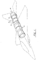
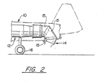
- the engine generally indicated by reference numeral 10 is mounted in an aircraft generally indicated by reference numeral 12 which engine includes the axisymmetrical exhaust nozzle generally indicated by reference numeral 14 and the three bearing ducts generally indicated by reference numeral 15.
- the ducts 15 are capable of being counter-rotated and as shown in Fig. 1 are positioned for horizontal flight condition and in Fig. 2 for STOVL condition. Positioning the nozzle for obtaining the vectoring feature is by articulating the three ducts to rotate around the respective bearings to attain the desired attitude.
- the length of the exhaust nozzle is sufficiently short so that it doesn't touch the ground.
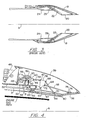
- Fig. 3 exemplifies a typical prior art exhaust nozzle that if utilized in the embodiment disclosed in Figs. 1 and 2, would not be capable of meeting the criteria noted above.
- the exhaust nozzle consists of the external flaps 18, divergent flaps 20 and convergent flaps 22.
- the prior art exhaust nozzles require balancing flaps which are depicted by reference numerals 24 and 26.
- reference numerals 24 and 26 For a more detailed description of the prior art exhaust nozzle reference should be made to US Patent No. 3,792,815, as mentioned above.
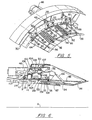
- Fig. 4 which does not form part of the invention, shows a compact axisymmetrical exhaust nozzle comprised of a combined actuator synchronizing ring and pressure balancing piston (PBSR) 30, fulcrum links 32, convergent flaps 34, divergent flaps 36 and the attendant connecting links as will be more fully described hereinbelow.
- An external flap 39 for providing an aerodynamically clean surface is also provided.
- the fulcrum 32 which is generally triangularly shaped is operatively connected to the hydraulic actuator 46 by the link 38 which is pivotally connected to pivot 40 and the connecting link 42 which is pivotally connected to pivot 44. In this embodiment three actuators are equally spaced about the axis A.
- the PBSR 30 consists of a toroidally shaped housing 48 that is coaxially mounted relative to the engine's center axis A and is completely enclosed by virtue of the static annular structure 50 for defining chamber 52.
- Chamber 52 is divided into sub-chambers 54 and 56 by the radially extending annular member 58.
- the housing 48 moves axially relative to the static structure 50 and the chamber 56 serves as a working chamber such that the fluid admitted therein acts against the inner surface 60 of housing 48 much like the action of a typical piston.
- This pressure serves to urge the housing 48 toward the right as the pressure builds up in chamber 56 urging the connecting member 42 and link 38 to rotate the fulcrum 32 about its pivot connection 62 to balance the load of the flaps.
- Links 64 and 66 are respectively connected to the convergent flaps 34 via the pivotal connections 68 and 70 and the divergent flaps 36 via the pivotal connection 72 and the sliding connection 74 sliding in track 76 which in turn is integrally formed on the back surface of the flap 36.
- the flaps 34 and 36 are hingedly connected to each other by the hinge connection 80 and the convergent flap is connected to the static structure 50 via the pivotal connection 82 and the fixed support arm 84.
- the PBSR 30 reacts the loads that are transmitted through the linkage and fulcrum from the convergent flaps and the divergent flaps to balance the load produced thereby.
- this serves a similar purpose as the balancing flaps disclosed in US 3,792,815 supra, so that these components are eliminated and a significant reduction in the C/D nozzle length is realized.
- a cooling liner 87 may be attached to the flap 34 for assuring the structural integrity of the parts.
- the cooling liner 87 is radially spaced from the flap 34 to define an axial passage for flowing fan air therein to cool the convergent flap.
- the conventional seal flaps 92 are utilized to prevent the engine working medium from escaping from the gas path between adjacent flaps.
- the actuators 46 are actuated by fuel (not shown) in a well known manner which causes the actuator connecting rod 86 to move toward the right.
- fuel not shown
- the pressure from the fan discharge air depicted by arrows B which is admitted through a plurality of holes 90 spaced around the circumference (one being shown) causes the PBSR 30 to add to the force produced by actuator 46.
- This force is transmitted to the fulcrum 32 via the linkages as described above.
- the fulcrum 32 positions the flaps to the desired C/D configuration.
- the actuator 46 (like parts depicted in all the Figs. bear the same reference numerals) is mounted generally within the synchronization ring (PBSR) 30.
- the PBSR 30 comprises the housing 102 which is generally U-shaped in cross section and carries a pair of diametrically spaced pockets 104 supporting rollers 105 that each roll on the surface of annular static structures 107 and 109.
- the PBSR is disposed between said pair of annular static structures 107, 109. These surfaces are sealing surfaces and require suitable sealing members.
- the working chamber 108 similar to the working chamber 56 in Fig. 4, receives pressurized fan discharge air depicted by arrows B.
- the mounting bracket 112 supporting the actuator 46 is designed so that the bracket is attached to flanges 111 and 113 formed on the aligned annular static structures 117 and 119 and secured by a plurality of nuts and bolts 114 (one being shown).
- the pivot support includes an annular frame with opposing flanges 129 and 131 that are bolted to the underside of the static structure 119. This allows the depending flange 133 to be retracted radially outwardly which allows the pivot point 139 to be raised and positioned away from the inlet to the cooling passageway formed between the flap surface of flap 34 and the inner surface of liner 87, resulting in improved cooling of the convergent flaps.
- the present invention provides an improved axisymmetrical C/D exhaust nozzle, in which the actuation rod of the hydraulic actuator is enclosed and aligned with the synchronization ring.
- the preferred embodiment permits the exhaust nozzle to remain a full-hoop structure eliminating the weakening cut-outs and facilitating fabrication with these benefits:
Landscapes
- Engineering & Computer Science (AREA)
- Chemical & Material Sciences (AREA)
- Combustion & Propulsion (AREA)
- Mechanical Engineering (AREA)
- General Engineering & Computer Science (AREA)
- Control Of Turbines (AREA)
Applications Claiming Priority (2)
| Application Number | Priority Date | Filing Date | Title |
|---|---|---|---|
| US721888 | 1996-09-27 | ||
| US08/721,888 US5794850A (en) | 1996-09-27 | 1996-09-27 | Enclosed pressure balanced sync ring nozzle |
Publications (3)
| Publication Number | Publication Date |
|---|---|
| EP0833047A2 EP0833047A2 (en) | 1998-04-01 |
| EP0833047A3 EP0833047A3 (en) | 1999-10-27 |
| EP0833047B1 true EP0833047B1 (en) | 2003-07-09 |
Family
ID=24899728
Family Applications (1)
| Application Number | Title | Priority Date | Filing Date |
|---|---|---|---|
| EP97307622A Expired - Lifetime EP0833047B1 (en) | 1996-09-27 | 1997-09-29 | Pressure balanced synchronizing nozzle |
Country Status (5)
| Country | Link |
|---|---|
| US (1) | US5794850A (enExample) |
| EP (1) | EP0833047B1 (enExample) |
| JP (1) | JP3968672B2 (enExample) |
| KR (1) | KR100452668B1 (enExample) |
| DE (1) | DE69723381T2 (enExample) |
Families Citing this family (17)
| Publication number | Priority date | Publication date | Assignee | Title |
|---|---|---|---|---|
| ES2194171T3 (es) * | 1997-01-23 | 2003-11-16 | Turbo Propulsores Ind | Petalo divergente para una tobera de motor de turbina de gas. |
| US6212877B1 (en) * | 1998-09-04 | 2001-04-10 | General Electric Company | Vectoring ring support and actuation mechanism for axisymmetric vectoring nozzle with a universal joint |
| FR2860046B1 (fr) * | 2003-09-19 | 2005-12-02 | Snecma Moteurs | Volet chaud commande de tuyere axisymetrique de turboreacteur |
| US7458221B1 (en) * | 2003-10-23 | 2008-12-02 | The United States Of America As Represented By The Administrator Of The National Aeronautics And Space Administration | Variable area nozzle including a plurality of convexly vanes with a crowned contour, in a vane to vane sealing arrangement and with nonuniform lengths |
| US20080072604A1 (en) * | 2006-09-26 | 2008-03-27 | United Technologies Corporation | Pressure balance control for gas turbine engine nozzle |
| US7854124B2 (en) * | 2006-10-27 | 2010-12-21 | United Technologies Corporation | Combined control for supplying cooling air and support air in a turbine engine nozzle |
| US9719370B2 (en) * | 2007-03-30 | 2017-08-01 | United Technologies Corporation | Linkage system with wear reduction |
| US7716932B2 (en) * | 2008-07-24 | 2010-05-18 | Spirit Aerosystems, Inc. | Dilating fan duct nozzle |
| US20130145768A1 (en) * | 2011-12-08 | 2013-06-13 | Honeywell International Inc. | Case assembly with fuel or hydraulic driven vafn actuation systems |
| US9091230B2 (en) * | 2012-05-16 | 2015-07-28 | The Boeing Company | Linked ring petal actuation for variable area fan nozzle |
| WO2014160509A1 (en) | 2013-03-13 | 2014-10-02 | Rolls-Royce North American Technologies, Inc. | Gas turbine engine with three stream, variable area, vectorable nozzle |
| US9689346B2 (en) | 2013-04-12 | 2017-06-27 | United Technologies Corporation | Gas turbine engine convergent/divergent exhaust nozzle divergent seal with dovetail interface |
| WO2014200402A1 (en) * | 2013-06-14 | 2014-12-18 | Saab Ab | Variable-geometry convergent-divergent exhaust nozzle for a jet engine and method for varying the nozzle |
| US9488130B2 (en) | 2013-10-17 | 2016-11-08 | Honeywell International Inc. | Variable area fan nozzle systems with improved drive couplings |
| US10502091B2 (en) | 2016-12-12 | 2019-12-10 | United Technologies Corporation | Sync ring assembly and associated clevis including a rib |
| CN112761814A (zh) * | 2021-01-15 | 2021-05-07 | 中国航发沈阳发动机研究所 | 一种航空发动机喷管收敛片调节机构 |
| FR3119869B1 (fr) * | 2021-02-18 | 2023-02-10 | Safran Aircraft Engines | Partie arrière de turboréacteur comprenant une tuyère à loi a9/a8 étendue |
Family Cites Families (12)
| Publication number | Priority date | Publication date | Assignee | Title |
|---|---|---|---|---|
| US3792815A (en) | 1972-11-24 | 1974-02-19 | United Aircraft Corp | Balanced flap converging/diverging nozzle |
| GB1444391A (en) * | 1973-05-02 | 1976-07-28 | Rolls Royce | Exhaust nozzle structures |
| FR2244917B2 (enExample) | 1973-09-21 | 1978-01-13 | Snecma | |
| US4000854A (en) * | 1975-10-02 | 1977-01-04 | General Electric Company | Thrust vectorable exhaust nozzle |
| US4049198A (en) * | 1976-06-17 | 1977-09-20 | The United States Of America As Represented By The Secretary Of The Air Force | Duct pressure actuated nozzle |
| GB2254377B (en) * | 1981-02-28 | 1993-03-31 | Rolls Royce | Pressure balanced variable area nozzle |
| US4440347A (en) | 1981-12-28 | 1984-04-03 | United Technologies Corporation | Simplified means for balancing the loads on a variable area nozzle |
| US4440346A (en) | 1981-12-28 | 1984-04-03 | United Technologies Corporation | Axially translatable variable area convergent/divergent nozzle |
| US4420932A (en) * | 1982-03-02 | 1983-12-20 | The United States Of America As Represented By The Secretary Of The Air Force | Pressure control system for convergent-divergent exhaust nozzle |
| US4456178A (en) | 1982-12-27 | 1984-06-26 | United Technologies Corporation | Exhaust nozzle assembly with dual unison ring structure |
| US5011080A (en) | 1990-04-18 | 1991-04-30 | United Technologies Corporation | Convergent/divergent nozzle construction |
| US5215256A (en) | 1992-07-16 | 1993-06-01 | Barcza W Kevin | Flap hinge arrangement for a convergent/divergent nozzle |
-
1996
- 1996-09-27 US US08/721,888 patent/US5794850A/en not_active Expired - Lifetime
-
1997
- 1997-09-25 JP JP27668197A patent/JP3968672B2/ja not_active Expired - Fee Related
- 1997-09-26 KR KR1019970049133A patent/KR100452668B1/ko not_active Expired - Fee Related
- 1997-09-29 EP EP97307622A patent/EP0833047B1/en not_active Expired - Lifetime
- 1997-09-29 DE DE69723381T patent/DE69723381T2/de not_active Expired - Fee Related
Also Published As
| Publication number | Publication date |
|---|---|
| KR100452668B1 (ko) | 2004-12-17 |
| EP0833047A3 (en) | 1999-10-27 |
| DE69723381D1 (de) | 2003-08-14 |
| DE69723381T2 (de) | 2004-04-15 |
| JP3968672B2 (ja) | 2007-08-29 |
| JPH10103154A (ja) | 1998-04-21 |
| KR19980025049A (ko) | 1998-07-06 |
| US5794850A (en) | 1998-08-18 |
| EP0833047A2 (en) | 1998-04-01 |
Similar Documents
| Publication | Publication Date | Title |
|---|---|---|
| EP0833046B1 (en) | Compact pressure balanced nozzle | |
| US5797544A (en) | C/D nozzle with synchronizing ring link suspension | |
| EP0833047B1 (en) | Pressure balanced synchronizing nozzle | |
| US5150839A (en) | Nozzle load management | |
| EP1873386B1 (en) | Fan variable area nozzle for a gas turbine engine fan nacelle | |
| EP2134949B1 (en) | Fan variable area nozzle for a gas turbine engine fan nacelle with drive ring actuation system | |
| JP2815206B2 (ja) | ガスタービンジェットエンジン | |
| US6415599B1 (en) | Engine interface for axisymmetric vectoring nozzle | |
| US6299077B1 (en) | Actuation system for convergent/divergent nozzle | |
| GB2313580A (en) | Power plant for producing variable direction efflux | |
| JPH0261617B2 (enExample) | ||
| US4714197A (en) | 2-D propulsive lift nozzle | |
| EP3816425B1 (en) | An exhaust nozzle for a gas turbine engine | |
| EP0544764B1 (en) | Axisymmetric nozzle with gimbled unison ring | |
| JP4578652B2 (ja) | 軸対称方向制御ノズルのための直線作動及び方向制御リング支持機構 | |
| EP0932755B1 (en) | An axisymmetric vectoring nozzle actuating system having multiple power control circuits | |
| US5054286A (en) | Bypass valve system | |
| US4447009A (en) | Three-dimensional axially translatable convergent/divergent nozzle assembly | |
| US6212877B1 (en) | Vectoring ring support and actuation mechanism for axisymmetric vectoring nozzle with a universal joint | |
| US5478016A (en) | Vectorable nozzle | |
| EP1995442B1 (en) | Turbine engine valve assembly | |
| EP1916405B1 (en) | Thrust vectorable fan variable area nozzle for a gas turbine engine fan nacelle | |
| GB2245656A (en) | Bypass valve system of a gas turbine engine | |
| CN1234850A (zh) | 喷管空心致动环 |
Legal Events
| Date | Code | Title | Description |
|---|---|---|---|
| PUAI | Public reference made under article 153(3) epc to a published international application that has entered the european phase |
Free format text: ORIGINAL CODE: 0009012 |
|
| AK | Designated contracting states |
Kind code of ref document: A2 Designated state(s): DE FR GB |
|
| AX | Request for extension of the european patent |
Free format text: AL;LT;LV;RO;SI |
|
| PUAL | Search report despatched |
Free format text: ORIGINAL CODE: 0009013 |
|
| AK | Designated contracting states |
Kind code of ref document: A3 Designated state(s): AT BE CH DE DK ES FI FR GB GR IE IT LI LU MC NL PT SE |
|
| AX | Request for extension of the european patent |
Free format text: AL;LT;LV;RO;SI |
|
| RIC1 | Information provided on ipc code assigned before grant |
Free format text: 6F 02K 1/00 A, 6F 02K 1/12 B, 6F 02K 1/15 B |
|
| 17P | Request for examination filed |
Effective date: 20000425 |
|
| AKX | Designation fees paid |
Free format text: DE FR GB |
|
| 17Q | First examination report despatched |
Effective date: 20020201 |
|
| GRAH | Despatch of communication of intention to grant a patent |
Free format text: ORIGINAL CODE: EPIDOS IGRA |
|
| GRAH | Despatch of communication of intention to grant a patent |
Free format text: ORIGINAL CODE: EPIDOS IGRA |
|
| GRAA | (expected) grant |
Free format text: ORIGINAL CODE: 0009210 |
|
| AK | Designated contracting states |
Designated state(s): DE FR GB |
|
| REG | Reference to a national code |
Ref country code: GB Ref legal event code: FG4D |
|
| REF | Corresponds to: |
Ref document number: 69723381 Country of ref document: DE Date of ref document: 20030814 Kind code of ref document: P |
|
| ET | Fr: translation filed | ||
| PLBE | No opposition filed within time limit |
Free format text: ORIGINAL CODE: 0009261 |
|
| STAA | Information on the status of an ep patent application or granted ep patent |
Free format text: STATUS: NO OPPOSITION FILED WITHIN TIME LIMIT |
|
| 26N | No opposition filed |
Effective date: 20040414 |
|
| PGFP | Annual fee paid to national office [announced via postgrant information from national office to epo] |
Ref country code: FR Payment date: 20080904 Year of fee payment: 12 |
|
| PGFP | Annual fee paid to national office [announced via postgrant information from national office to epo] |
Ref country code: DE Payment date: 20080930 Year of fee payment: 12 |
|
| REG | Reference to a national code |
Ref country code: FR Ref legal event code: ST Effective date: 20100531 |
|
| PG25 | Lapsed in a contracting state [announced via postgrant information from national office to epo] |
Ref country code: FR Free format text: LAPSE BECAUSE OF NON-PAYMENT OF DUE FEES Effective date: 20090930 Ref country code: DE Free format text: LAPSE BECAUSE OF NON-PAYMENT OF DUE FEES Effective date: 20100401 |
|
| PGFP | Annual fee paid to national office [announced via postgrant information from national office to epo] |
Ref country code: GB Payment date: 20150825 Year of fee payment: 19 |
|
| GBPC | Gb: european patent ceased through non-payment of renewal fee |
Effective date: 20160929 |
|
| REG | Reference to a national code |
Ref country code: DE Ref legal event code: R082 Ref document number: 69723381 Country of ref document: DE Representative=s name: SCHMITT-NILSON SCHRAUD WAIBEL WOHLFROM PATENTA, DE |
|
| PG25 | Lapsed in a contracting state [announced via postgrant information from national office to epo] |
Ref country code: GB Free format text: LAPSE BECAUSE OF NON-PAYMENT OF DUE FEES Effective date: 20160929 |