EP0831028A1 - Conveyor for a container-filling and/or closing machine - Google Patents
Conveyor for a container-filling and/or closing machine Download PDFInfo
- Publication number
- EP0831028A1 EP0831028A1 EP97115812A EP97115812A EP0831028A1 EP 0831028 A1 EP0831028 A1 EP 0831028A1 EP 97115812 A EP97115812 A EP 97115812A EP 97115812 A EP97115812 A EP 97115812A EP 0831028 A1 EP0831028 A1 EP 0831028A1
- Authority
- EP
- European Patent Office
- Prior art keywords
- transport device
- transport
- chain
- cell sheets
- cell
- Prior art date
- Legal status (The legal status is an assumption and is not a legal conclusion. Google has not performed a legal analysis and makes no representation as to the accuracy of the status listed.)
- Granted
Links
- 238000010168 coupling process Methods 0.000 claims abstract description 21
- 238000005859 coupling reaction Methods 0.000 claims abstract description 21
- 230000008878 coupling Effects 0.000 claims abstract description 20
- 230000013011 mating Effects 0.000 claims abstract description 4
- 235000013305 food Nutrition 0.000 claims description 6
- 238000007789 sealing Methods 0.000 claims description 5
- 235000011837 pasties Nutrition 0.000 claims description 3
- 239000007788 liquid Substances 0.000 claims description 2
- 235000013361 beverage Nutrition 0.000 claims 1
- 238000010276 construction Methods 0.000 claims 1
- 230000003993 interaction Effects 0.000 claims 1
- 230000004048 modification Effects 0.000 description 3
- 238000012986 modification Methods 0.000 description 3
- 230000009969 flowable effect Effects 0.000 description 1
- 239000011521 glass Substances 0.000 description 1
- 230000005484 gravity Effects 0.000 description 1
- 230000001771 impaired effect Effects 0.000 description 1
- 230000007257 malfunction Effects 0.000 description 1
- 239000002184 metal Substances 0.000 description 1
- 238000012544 monitoring process Methods 0.000 description 1
- 239000000725 suspension Substances 0.000 description 1
Images


Classifications
-
- B—PERFORMING OPERATIONS; TRANSPORTING
- B65—CONVEYING; PACKING; STORING; HANDLING THIN OR FILAMENTARY MATERIAL
- B65G—TRANSPORT OR STORAGE DEVICES, e.g. CONVEYORS FOR LOADING OR TIPPING, SHOP CONVEYOR SYSTEMS OR PNEUMATIC TUBE CONVEYORS
- B65G17/00—Conveyors having an endless traction element, e.g. a chain, transmitting movement to a continuous or substantially-continuous load-carrying surface or to a series of individual load-carriers; Endless-chain conveyors in which the chains form the load-carrying surface
- B65G17/30—Details; Auxiliary devices
- B65G17/38—Chains or like traction elements; Connections between traction elements and load-carriers
- B65G17/42—Attaching load carriers to traction elements
-
- B—PERFORMING OPERATIONS; TRANSPORTING
- B65—CONVEYING; PACKING; STORING; HANDLING THIN OR FILAMENTARY MATERIAL
- B65B—MACHINES, APPARATUS OR DEVICES FOR, OR METHODS OF, PACKAGING ARTICLES OR MATERIALS; UNPACKING
- B65B43/00—Forming, feeding, opening or setting-up containers or receptacles in association with packaging
- B65B43/42—Feeding or positioning bags, boxes, or cartons in the distended, opened, or set-up state; Feeding preformed rigid containers, e.g. tins, capsules, glass tubes, glasses, to the packaging position; Locating containers or receptacles at the filling position; Supporting containers or receptacles during the filling operation
- B65B43/52—Feeding or positioning bags, boxes, or cartons in the distended, opened, or set-up state; Feeding preformed rigid containers, e.g. tins, capsules, glass tubes, glasses, to the packaging position; Locating containers or receptacles at the filling position; Supporting containers or receptacles during the filling operation using roller-ways or endless conveyors
-
- B—PERFORMING OPERATIONS; TRANSPORTING
- B65—CONVEYING; PACKING; STORING; HANDLING THIN OR FILAMENTARY MATERIAL
- B65B—MACHINES, APPARATUS OR DEVICES FOR, OR METHODS OF, PACKAGING ARTICLES OR MATERIALS; UNPACKING
- B65B43/00—Forming, feeding, opening or setting-up containers or receptacles in association with packaging
- B65B43/42—Feeding or positioning bags, boxes, or cartons in the distended, opened, or set-up state; Feeding preformed rigid containers, e.g. tins, capsules, glass tubes, glasses, to the packaging position; Locating containers or receptacles at the filling position; Supporting containers or receptacles during the filling operation
- B65B43/54—Means for supporting containers or receptacles during the filling operation
-
- B—PERFORMING OPERATIONS; TRANSPORTING
- B65—CONVEYING; PACKING; STORING; HANDLING THIN OR FILAMENTARY MATERIAL
- B65B—MACHINES, APPARATUS OR DEVICES FOR, OR METHODS OF, PACKAGING ARTICLES OR MATERIALS; UNPACKING
- B65B59/00—Arrangements to enable machines to handle articles of different sizes, to produce packages of different sizes, to vary the contents of packages, to handle different types of packaging material, or to give access for cleaning or maintenance purposes
- B65B59/005—Adjustable conveying means
-
- B—PERFORMING OPERATIONS; TRANSPORTING
- B67—OPENING, CLOSING OR CLEANING BOTTLES, JARS OR SIMILAR CONTAINERS; LIQUID HANDLING
- B67C—CLEANING, FILLING WITH LIQUIDS OR SEMILIQUIDS, OR EMPTYING, OF BOTTLES, JARS, CANS, CASKS, BARRELS, OR SIMILAR CONTAINERS, NOT OTHERWISE PROVIDED FOR; FUNNELS
- B67C7/00—Concurrent cleaning, filling, and closing of bottles; Processes or devices for at least two of these operations
- B67C7/0006—Conveying; Synchronising
- B67C7/0026—Conveying; Synchronising the containers travelling along a linear path
-
- B—PERFORMING OPERATIONS; TRANSPORTING
- B65—CONVEYING; PACKING; STORING; HANDLING THIN OR FILAMENTARY MATERIAL
- B65B—MACHINES, APPARATUS OR DEVICES FOR, OR METHODS OF, PACKAGING ARTICLES OR MATERIALS; UNPACKING
- B65B59/00—Arrangements to enable machines to handle articles of different sizes, to produce packages of different sizes, to vary the contents of packages, to handle different types of packaging material, or to give access for cleaning or maintenance purposes
- B65B59/003—Arrangements to enable adjustments related to the packaging material
-
- B—PERFORMING OPERATIONS; TRANSPORTING
- B65—CONVEYING; PACKING; STORING; HANDLING THIN OR FILAMENTARY MATERIAL
- B65B—MACHINES, APPARATUS OR DEVICES FOR, OR METHODS OF, PACKAGING ARTICLES OR MATERIALS; UNPACKING
- B65B59/00—Arrangements to enable machines to handle articles of different sizes, to produce packages of different sizes, to vary the contents of packages, to handle different types of packaging material, or to give access for cleaning or maintenance purposes
- B65B59/04—Machines constructed with readily-detachable units or assemblies, e.g. to facilitate maintenance
-
- B—PERFORMING OPERATIONS; TRANSPORTING
- B65—CONVEYING; PACKING; STORING; HANDLING THIN OR FILAMENTARY MATERIAL
- B65G—TRANSPORT OR STORAGE DEVICES, e.g. CONVEYORS FOR LOADING OR TIPPING, SHOP CONVEYOR SYSTEMS OR PNEUMATIC TUBE CONVEYORS
- B65G2201/00—Indexing codes relating to handling devices, e.g. conveyors, characterised by the type of product or load being conveyed or handled
- B65G2201/02—Articles
Landscapes
- Engineering & Computer Science (AREA)
- Mechanical Engineering (AREA)
- Microelectronics & Electronic Packaging (AREA)
- Chain Conveyers (AREA)
- Supplying Of Containers To The Packaging Station (AREA)
Abstract
Description
Die Erfindung bezieht sich auf eine Transporteinrichtung an einer Behälter-Füll- und/oder Verschließmaschine, insbesondere für flüssige bis pastöse Produkte, wie beispielsweise Nahrungs- und Genußmittel mit einem kontinuierlich oder diskontinuierlich umlaufend angetriebenen, entlang von Führungsleisten geführten Transportmittel, durch das quer zur Transportrichtung nebeneinander angeordnete, zur Aufnahme von Behältern geeignete Zellenbleche entlang von Arbeitsstationen bewegbar sind.The invention relates to a transport device on a container filling and / or Sealing machine, especially for liquid to pasty products, such as Food and luxury goods with a continuous or discontinuous circulation driven, guided along guide rails, through the transverse arranged next to each other for the transport direction, for receiving containers suitable cell sheets can be moved along work stations.
Behälter-Füll- und/oder Verschließmaschinen werden oft nicht nur zum Abfüllen eines einzigen Produktes eingesetzt. Vielmehr wird häufig auf ein und derselben Maschine eine Vielzahl von fließfähigen und/oder pastösen Produkten abgefüllt. Diese Vielzahl an unterschiedlichen Produktfüllungen bedingt unterschiedliche Behälterformen und -größen und zwangsläufig damit auch den Einsatz unterschiedlich gestalteter Zellenbleche, da die Behälter in entsprechend angepaßten Behälteraufnahmen der Zellenbleche eingesetzt sind. Während die Zellenbleche in ihren Außenabmessungen immer gleich sind, müssen die Behälteraufnahmen stets den jeweiligen Behältergrößen entsprechen, so daß bei jedem Produktwechsel mit unterschiedlichen Behältern auch die Zellenbleche auszuwechseln sind.Container filling and / or capping machines are often not just for filling one single product used. Rather, it is often on the same machine bottled a variety of flowable and / or pasty products. This multitude of different product fillings require different container shapes and sizes and inevitably also the use of differently designed Cell sheets, as the containers in the container receptacles which have been adapted accordingly Cell sheets are used. While the cell sheets in their outer dimensions are always the same, the container receptacles must always correspond to the respective container sizes correspond, so that with each product change with different containers Cell sheets must be replaced.
Ein Formatwechsel muß einfach und schnell durch den Maschinenbediener durchgeführt werden können. Der größte zeitliche Aufwand bei einem Formatwechsel fällt für den Umtausch der Zellenbleche an. Dies ist deshalb der Fall, weil jeweils an den Schmalseiten der Zellenbleche angeordnete Schraubverbindungen zur Befestigung an mit dem Transportmittel, beispielsweise Transportketten verbundenen Winkellaschen gelöst, danach die benutzten Zellenbleche herausgenommen und gegen andersformatige Zellenbleche ersetzt und danach schließlich die Schraubverbindungen wieder hergestellt werden müssen. Hinzu kommt, daß beim Wechsel die Zellenbleche genau ausgerichtet werden müssen, damit in einer Arbeitsstation, z. B. in einer Siegelstation die Zellenbleche bzw. die darin befindlichen Behälteraufnahmen mit den eingesetzten Behältern paßgenau unterhalb des Siegelwerkzeugs zu liegen kommen. Andernfalls wird die Siegelqualität nachhaltig beeinträchtigt. Nach wiederholter Montage und Demontage der Zellenbleche sind diese durch das Hantieren mit Werkzeugen zum Lösen der Verschraubungen oft stark beschädigt, so daß sie gegen neue ausgetauscht werden müssen. Aufgrund der über die Oberfläche der Zellenbleche vorstehenden Verschraubungs- und/oder Befestigungselemente lassen sich solcherart befestigte Zellenbleche auch nur schlecht reinigen.A change of format must be carried out quickly and easily by the machine operator can be. The biggest time effort for a format change falls for the Exchange of the cell sheets. This is the case because at the Screw connections arranged on the narrow sides of the cell sheets for fastening angle brackets connected to the means of transport, for example transport chains solved, then the used cell sheets removed and counter different-sized cell sheets replaced and then finally the screw connections need to be restored. In addition, when changing the cell sheets must be precisely aligned so that in a workstation, e.g. B. in one Sealing station the cell sheets or the container receptacles located therein with the used containers come to lie exactly below the sealing tool. Otherwise the seal quality will be permanently impaired. After repeated assembly and disassembly of the cell sheets are done by handling tools Loosening the screw connections often severely damaged so that they can be exchanged for new ones Need to become. Because of the protruding above the surface of the cell sheets Screwing and / or fastening elements can be fastened in this way Badly clean cell sheets.
Aus der deutschen Patentschrift 35 38 993 ist es zwar schon bekanntgeworden, zum
Zweck einer schnelleren und einfacheren Auswechslung der Zellenbleche einen
Manipulator einzusetzen, durch den die Schraubverbindung mit Hilfe eines motorisch
betriebenen Schraubers automatisch gelöst und nach dem Wechsel diese Verbindung
auch wieder hergestellt wird. Das jeweils gelöste Zellenblech wird dabei beispielsweise
durch Saugnäpfe des Manipulators aufgenommen und in ein Magazin gefördert. Mit Hilfe
einer Zange wird ein neues Zellenblech in die Transporteinrichtung eingesetzt und
danach wieder über den Manipulator mit dem Transportmittel verschraubt. Durch den
Einsatz eines Manipulators mit als Schrauber ausgebildetem Werkzeug wird zwar die
bisher manuell benötigte Zeit reduziert. Das Anschrauben mittels Sechskantmuttern,
Befestigungsschrauben und Winkellaschen benötigt aber immer noch eine gewisse Zeit.
Außerdem ist dieser Verriegelungs- und Entriegelungsmechanismus sehr
kostenaufwendig und es kann bei Beschädigung des Gewindeansatzes der
Beschraubungsbolzen weiterhin zu Betriebsstörungen kommen. Schließlich ist diese
Befestigung zum Abfüllen von Lebensmittelprodukten nach wie vor hygienisch
bedenklich.From the
Aus der deutschen Patentschritt 37 43 278 ist eine Vorrichtung zum automatischen
Auswechseln von behälteraufnehmenden Zellenblechen mittels eines gewindelosen
Verriegelungs- und Entriegelungsmechanismus erfolgt. In diesem Fall sind an an den
Kettengliedern befestigten Winkellaschen aufrechtstehende Bolzen angeordnet, die die
Zellenbleche aufnehmen und die mit einer Verschlußkupplung versehen ist. Bei dieser
Vorrichtung wird zwar auf eine Verschraubung verzichtet, jedoch ist der maschinelle
Aufwand sehr beträchtlich, da die als Steckverschlüsse ausgebildeten
Kupplungselemente relativ teuer sind. Schließlich ist auch diese Ausführung bei
Abfüllmaschinen für Lebensmittel hygienisch bedenklich.From the
Der Erfindung liegt die Aufgabe zugrunde, eine Transporteinrichtung der eingangs genannten Art zu schaffen, die eine noch einfachere und schnellere und vor allen Dingen preiswertere Auswechslung von Zellenblechen ermöglicht und sich durch eine paßgenaue und stabile Lage der Zellenbleche sowie auch eine den Hygienevorschriften für Lebensmittel geeignete Ausbildung auszeichnet.The invention has for its object a transport device at the beginning to create the kind that is even easier and faster and above all Things cheaper replacement of cell sheets made possible and by one precise and stable position of the cell sheets as well as one of the hygiene regulations training suitable for food.
Diese Aufgabe wird erfindungsgemäß dadurch gelöst, daß die Zellenbleche mit dem Transportmittel durch an den Zellenblechen angeordnete Kupplungselemente sowie am Transportmittel angeordnete, jeweils mit den Kupplungselementen zusammenwirkende Gegenkupplungselemente ohne Verwendung von zu lösenden Verschraubungen oder dergleichen antriebsmäßig verbindbar und während der Umlaufbewegung des Transportmittels durch die Führungsleisten gegen Herausfallen gesichert sind.This object is achieved in that the cell sheets with the Transport means arranged on the cell sheets coupling elements and on Transport means arranged, each interacting with the coupling elements Mating coupling elements without using screw connections or The same can be connected in terms of drive and during the orbital movement of the Means of transport are secured against falling out by the guide rails.
Mit den Mitteln nach der Erfindung kommt man zu einer Transporteinrichtung, die sich durch einen besonders einfachen und preisgünstigen Aufbau auszeichnet und vor allen Dingen ein überaus schnelles Wechseln der in der Maschine befindlichen Zellenbleche gegen andersformatige, in die Maschine einzusetzende Zellenbleche auszeichnet. Durch die erfindungsgemäße Befestigung ist die Oberfläche aufgrund der fehlenden Befestigungselemente vollständig glatt, so daß den Hygienevorschriften für Lebensmittel entsprochen wird.With the means according to the invention, one arrives at a transport device which itself characterized by a particularly simple and inexpensive structure and above all Thing an extremely quick change of the cell sheets in the machine against different-sized cell sheets to be inserted into the machine. By the attachment according to the invention is the surface due to the lack of Fasteners completely smooth, so that the hygiene regulations for food is met.
Von besonderem Vorteil ist, daß die Kupplungselemente von an gegenüberliegenden Seiten der Zellenbleche angeordneten Mitnehmerlaschen und die Gegenkupplungselemente des von zwei mit Abstand zueinander endlos umlaufend angetriebenen Ketten oder dergleichen, vorzugsweise Rollenketten gebildeten Transportmittels von über die Kettenglieder seitlich überstehenden Kettengliedbolzen gebildet sind. Hierdurch wird vor allen Dingen sichergestellt, daß die Mitnehmerlaschen an der genauestmöglichen Stelle der Transportkette paßgenau fixiert eingehängt sind, so daß keine präzisen Bohrungen in den Winkellaschen mehr erforderlich sind.It is particularly advantageous that the coupling elements from opposite to Driver tabs arranged on the sides of the cell sheets and the Mating coupling elements of the endlessly rotating of two at a distance from one another driven chains or the like, preferably roller chains formed Means of transport for chain link bolts protruding laterally over the chain links are formed. This ensures above all that the driver plates are securely attached to the most precise possible point in the transport chain, so that precise holes in the angle brackets are no longer required.
Das gilt insbesondere für den Fall, daß die Mitnehmerlaschen im Querschnitt im wesentlichen U-förmig ausgebildet sind und deren mit Abstand gegenüberliegende Seitenwandungen die jeweils zugeordnete Transportkette reiterartig umgreifen. Auf diese Weise wird eine doppelte Abstützung bzw. Einhängung gewährleistet, so daß sich eine noch stabilere Lage ergibt. Dazu trägt ferner bei, daß in jeder Seitenwandung der Mitnehmerlaschen wenigstens eine, vorzugsweise zwei Lagerausnehmungen angeordnet sind, die mit entsprechend beidseitig über die Kettenglieder vorstehenden Bolzenteilen der Kettengliedbolzen zusammenwirken, dergestalt, daß die Mitnehmerlaschen lose eingehängt sind.This applies in particular to the case where the drive tabs in cross section in are substantially U-shaped and their opposite one another Side walls encompass the respective assigned transport chain like a rider. On in this way, a double support or suspension is guaranteed, so that results in an even more stable position. This also contributes to the fact that in each side wall Driver tabs at least one, preferably two bearing recesses are arranged, which protrude correspondingly on both sides of the chain links Bolt parts of the chain link bolts cooperate in such a way that the Driving tabs are loosely attached.
Theoretisch könnten die Mitnehmerlaschen einstückig mit den Zellenblechen ausgebildet sein, vorzugsweise sind diese jedoch zusätzlich durch einen Stift zentriert, an dem Zellenblech fest angeschraubt. Diese Verschraubung wird nicht beim Zellenblechwechsel gelöst. Außerdem befindet sich die Verschraubung auf der Unterseite (Sackbohrung), so daß die Oberfläche der Zellenbleche vollständig glatt ist.In theory, the driver tabs could be formed in one piece with the cell sheets be, but preferably these are additionally centered by a pin on the Cell panel firmly screwed on. This screw connection is not used when changing the cell sheet solved. In addition, the screw connection is on the underside (blind hole), see above that the surface of the cell sheets is completely smooth.
Damit eine noch weitergehende stabile Lage, insbesondere auch in den Umlenk- und Wendebereichen der Transporteinrichtung erreicht wird, sind an der Außenseite der außenliegenden Seitenwandung Führungsflächen vorgesehen, die mit im Längsbereich der Transporteinrichtung befindlichen Gleitschienen und/oder im Umlenk- bzw. Wendebereich der Transporteinrichtung angeordneten, halbkreisförmig ausgebildeten Gleitelementen zusammenwirken.So that an even more stable position, especially in the deflection and Turning areas of the transport device are reached on the outside of the outer side wall guide surfaces provided with in the longitudinal area of the transport device and / or in the deflection or Turning area of the transport device arranged, semi-circular Interact sliding elements.
Schließlich wird ein Zellenblechwechsel in besonderem Maße dadurch begünstigt, daß die Gleitschienen und diese tragende Abstützkörper im Längsbereich der Transporteinrichtung auf einem zum Einbringen und/oder entfernen von Zellenblechen geeigneten Teilstück unterbrochen ausgebildet sind und in dieser Unterbrechung jeweils ein aufklappbarer und verschließbarer Niederhalter angeordnet ist.Finally, a cell sheet change is particularly favored by the fact that the slide rails and this supporting body in the longitudinal region of the Transport device on one for inserting and / or removing cell sheets suitable section are formed interrupted and in this interruption each a hinged and closable hold-down device is arranged.
Bevorzugte Ausführungsbeispiele der Erfindung sind in der Zeichnung dargestellt und
werden im folgenden näher erläutert. Es zeigen:
eine schematische Darstellung einer Transporteinrichtung einer Behälter-Füll- und Verschließmaschine,
eine Aufsicht auf ein Zellenblech in in bezug auf Fig. 1 vergrößertem Maßstab,
die zugehörige Vorderansicht des Zellenblechs,
eine Seitenansicht des Zellenblechs in teilweisem Längsschnitt,
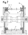
einen Teil der Transporteinrichtung im Bereich des Antriebs in in bezug auf Fig. 1 vergrößertem Maßstab,
einen teilweisen Querschnitt durch die Transporteinrichtung in deren Längsbereich,
einen teilweisen Querschnitt durch die Transporteinrichtung in deren Antriebs(Spann)bereich,
eine der Figur 1 entsprechende schematische Darstellung der Transporteinrichtung mit wahlweise einsetzbaren Wechselmöglichkeiten für die Zellenbleche,
eine alternative Ausführung einer Kupplungseinrichtung für die Kupplungsmitnahme der Zellenbleche durch das Transportmittel,
einen teilweisen Querschnitt durch die in
eine weitere Abwandlung der Transporteinrichtung,
einen teilweisen Querschnitt durch die in Fig. 11 dargestellte Transporteinrichtung und
eine Aufsicht auf einen Teilausschnitt einer Transportkette zur Anwendung bei einer in den
1 shows a schematic illustration of a transport device of a container filling and closing machine,
2 shows a plan view of a cell sheet on an enlarged scale in relation to FIG. 1,
the associated front view of the cell plate,
a side view of the cell sheet in partial longitudinal section,
a part of the transport device in the area of the drive on an enlarged scale with respect to FIG. 1,
a partial cross section through the transport device in its longitudinal region,
a partial cross section through the transport device in its drive (clamping) area,
FIG. 1 shows a schematic representation of the transport device corresponding to FIG. 1 with alternatively usable change options for the cell sheets,
an alternative embodiment of a coupling device for the coupling entrainment of the cell sheets by the means of transport,
9 shows a partial cross section through the transport device shown in FIG. 9,
a further modification of the transport device,
a partial cross section through the transport device shown in Fig. 11 and
a plan view of a partial section of a transport chain for use in a transport device shown in Figures 11 and 12.
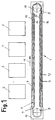
In Figur 1 ist eine Transporteinrichtung 1 einer im einzelnen nicht dargestellten Behälter-Füll- und Verschließmaschine dargestellt. Nur andeutungsweise sind von der Behälter-Füll- und Verschließmaschine eine Behälterzuführstation 2, eine Füllstation 3, eine
Deckelzuführstation 4 und eine Siegelstation 5 angedeutet. Die Transporteinrichtung 1
weist ein endlos umlaufendes Transportmittel in Form von zwei mit Abstand zueinander
angeordneten Transportketten 7 auf, die auf einer Spannseite und auf einer
Antriebsseite um dort vorgesehene Umlenkräder 8 geführt sind. Zwischen den
Transportketten 7 erstrecken sich Zellenbleche 9, die zur Aufnahme von zu füllenden
Behältern aus Kunststoff, Pappe, Papier, Glas, Blech oder dergleichen dienen. Während
der Vorwärtsbewegung des Transportmittels 6 in Richtung des Pfeils 11 lassen sich die
in weiter unten näher beschriebener Weise mit den Transportketten 7 verbindbaren
Zellenbleche 9 durch die Behälter-Füll- und Verschließmaschine bewegen, wobei sie
nacheinander unterhalb der Arbeitsstationen 2 bis 5 vorbeibewegt werden. Zur Führung
der über Kupplungselemente 12 mit den Transportketten 7 verschraubungslos
kuppelbaren Zellenbleche 9 dienen im Bereich des Obertrums des Transportketten 7
befindliche Führungsleisten 13, 14 sowie im Bereich des unteren Trums der
Transportketten 7 befindliche Führungsleisten 15, 16. Die Ausgestaltung dieser
Führungsleisten wird weiter unten näher erläutert. In den Umkehr- und Wendebereichen
auf der Spannseite und der Antriebsseite der Transporteinrichtung 1 befinden sich
gleichfalls zur Führung der Zellenbleche bzw. der Kupplungselemente 12 dienende
Gleitelemente 17, 18.1 shows a transport device 1 of a container filling and closing machine, not shown in detail. Only a hint of the container filling and closing machine are a
In den Figuren 2 bis 4 ist ein Zellenblech 9 dargestellt. Dieses weist nur beispielhaft eine
zentrische Öffnung 19 zur Aufnahme eines dort nicht dargestellten Behälters auf. Im
Bereich der beiden Stirnseiten des Zellenblechs 9 sind die Kupplungselemente 12
befestigt. Die als Mitnehmerlaschen ausgebildeten Kupplungselemente sind im
Querschnitt U-förmig ausgebildet und besitzen jeweils eine die zugeordnete
Transportkette 7 umgreifende Seitenwandung 21, 22 sowie einen die beiden
Seitenwandungen miteinander verbindenden Stegteil 23. Im Bereich des Stegteils 23 ist
die Mitnehmerlasche 12 über eine Sechskantschraube 24 an der Unterseite des
Zellenblechs 9 befestigt. Zur Zentrierung ist von der Unterseite her ein Stift 25
eingesetzt. Die außen liegende Seitenwandung 21 weist einen außerhalb der Stirnkante
des Zellenblechs 9 liegenden Verlängerungsteil 26 auf, der an seiner Außenseite und an
seiner im wesentlichen rechtwinklig dazu verlaufenden Stirnkante Führungsflächen 27,
28 zum Zusammenwirken mit den vorzugsweise aus Kunststoff hergestellten
Gleitelementen 17, 18 in den Umlenk- und Wendebereichen der Transporteinrichtung 1
aufweist.A
Aus Figur 3 ist ersichtlich, daß in den Seitenwandungen 21, 22 zwei mit Abstand
zueinander liegende Lagerausnehmungen 29 vorgesehen sind, die einseitig offen sind
und an ihren einander zugewandten Innenseiten eine Schräge 31 aufweisen. Diese
Schrägen 31 erleichtern das Einhängen der Mitnehmerlaschen 12 bzw. der Zellenbleche
9 auf seitlich überstehende Bolzenteile 32 von Kettengliedbolzen 33 (Fig. 5), die in
bekannter Weise zur Verbindung der einzelnen Kettenglieder der Transportketten 7
dienen. Insgesamt ist in diesem Bereich die Ausgestaltung der Mitnehmerlaschen 12
derart, daß sich die Lagerausnehmungen 29 jeweils im Bereich eines hakenförmig
ausgebildeten Teils der Mitnehmerlasche 12 befinden.From Figure 3 it can be seen that in the
Figur 5 zeigt weiterhin, daß zwischen den mittig an den Zellenblechen 9 befestigten
Mitnehmerlaschen 12 im Bereich zweier benachbart zueinanderliegender Zellenbleche 9
speziell ausgestaltete Abstützlaschen 34 vorgesehen sind, durch die sichergestellt wird,
daß die Zellenbleche 9 im Längsbereich der Transporteinrichtung 1 nicht kippen können.Figure 5 also shows that between the middle of the
Aus der in Figur 6 gezeigten Schnittdarstellung durch den Längsbereich der
Transporteinrichtung 1 ist ersichtlich, daß die im Bereich jeder Transportkette 7 oben
liegende Gleitschiene 13 an einem Abstützträger 35 befestigt ist, der seinerseits an
einem Rahmen 36 der Transporteinrichtung 1 befestigt ist. Die vorzugsweise als
Rollenkette ausgebildete Transportkette 7 stützt sich ihrerseits im oberen Bereich an der
Gleitschiene 14 ab, die selbst wiederum auf einem Abstützträger 37 ruht. In
entsprechender Weise ist im Bereich des unteren Trums jeder Transportkette 7 die dort
befindliche Gleitschiene 15 nach oben hin an einem Abstützträger 38 abgestützt und die
unten liegende Gleitschiene 16 an einem entsprechend ausgebildeten Abstützträger 39.From the sectional view shown in Figure 6 through the longitudinal region of the
Transport device 1 can be seen that in the area of each
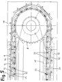
In den Umlenk- und Wendebereichen der Transporteinrichtung 1 (Figur 7) erfolgt die
Abstützung der Zellenbleche 9 an den hier sich gleichfalls erstreckenden Gleitschienen
13 und an den gleichfalls aus Kunststoff hergestellten, halbkreisförmig ausgebildeten
Gleitelementen 17 bzw. 18.This takes place in the deflection and turning areas of the transport device 1 (FIG. 7)
Support of the
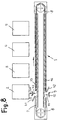
In Figur 8 sind zwei Möglichkeiten für das Einsetzen und das Entfernen von
Zellenblechen 9 dargestellt. In beiden Fällen ist vorgesehen, daß im Längsbereich der
Transporteinrichtung die Gleitschienen 13 und 16 einschließlich ihrer Abstützträger 35,
39 auf einem Teilstück unterbrochen sind und in diese Unterbrechung jeweils ein
aufklappbarer und verschließbarer Niederhalter 41, 42 eingesetzt ist, der gegebenenfalls
durch den Einsatz einer Lageüberwachung bezüglich seiner Offen- oder Geschlossen-Stellung
kontrolliert steuerbar ist. Bei geöffnetem Niederhalter 41 können über die so
entstandene Öffnung auszutauschende Zellenbleche 9 entnommen werden, so wie dies
durch den nach oben weisenden Pfeil 40 angedeutet ist. Gleichzeitig können aber auch
bei dieser Ausführungsvariante an der gleichen Stelle entsprechend dem Pfeil 43
andersformatige Zellenbleche wieder in die Transporteinrichtung eingesetzt werden. Die
Zellenbleche können manuell entnommen und eingesetzt werden. Durch eine geeignete
Schaltung, beispielsweise eine Zweihandschaltung, wird die Transportkette jeweils nach
Entnahme eines Zellenblechs 9 taktweise weitergeschaltet und zwar so lange, bis ein
kompletter Umlauf der Transportkette 7 durchgeführt ist.In Figure 8 there are two options for inserting and removing
Bei einer abgewandelten Ausführungsvariante werden neue Zellenbleche 9 gemäß der
vorbeschriebenen Darstellung entsprechend dem Pfeil 43 am Niederhalter 41 eingesetzt,
wenn dieser sich in seiner Offenstellung befindet. An dem geöffneten unten liegenden
Niederhalter 42 lassen sich die Zellenbleche 9 entsprechend der Pfeilangabe 44
entnehmen bzw. diese Zellenbleche fallen aufgrund ihrer Schwerkraft bei geöffnetem
Niederhalter nach unten und können dort von einem beispielsweise trommelartig oder
schachtartig ausgebildeten Zellenblechmagazin aufgenommen werden.
Selbstverständlich kann anstelle eines manuellen Wechsels der Zellenbleche 9
grundsätzlich auch ein automatischer Wechsel erfolgen.In a modified embodiment variant,
Bei einer in den Figuren 9 und 10 dargestellten Abwandlung der Transporteinrichtung 1
weist die Mitnehmerlasche 12 keine Seitenwandungen 21, 22 auf. Dafür besitzt sie an
der Unterseite ihres Stegteils 23 einen Mitnahmestift 45, die direkt zwischen Rollen 46
einer als Rollenkette 47 ausgebildeten Transportkette 7 eingesetzt wird. Auf diese Weise
werden die jeweils zugehörigen Zellenbleche 9 an der Rollenkette 47 fixiert. Wie aus
Figur 9 ersichtlich, weisen die Mitnahmestifte 45 einen mit T bezeichneten
Teilungsabstand auf. Entsprechend diesem Teilungsabstand sind am Außenumfang der
Umlenkräder 8 der Transporteinrichtung 1 Zahnlücken 48 vorgesehen, in die die
Mitnahmestifte 45 während des Umlaufs im Umlenk- bzw. Wendebereich eingreifen. Die
Abstützung der Zellenbleche kann erforderlichenfalls wiederum durch entsprechende
Gleitelemente 18 erfolgen, wie das weiter oben bereits beschrieben worden ist.In a modification of the transport device 1 shown in FIGS. 9 and 10
the
In den Figuren 11 bis 13 ist eine weitere Abwandlung der Transporteinrichtung 1
dargestellt. Hier befindet sich in jeder Seitenwandung 21, 22 der Mitnehmerlaschen 12
ein Randausschnitt 49, mittels der die Mitnehmerlasche 12 über seitlich vorstehende
Aufnahmetaschen 51 von Kettenlaschen 52 der Transportkette 7 greift und auf diese
Weise eine Kupplung der Zellenbleche 9 mit der Transportkette 7 gewährleistet. Die
Führung im Umlenkbereich erfolgt entweder wie bei den oben beschriebenen
Ausführungen oder aber auch in der Weise, daß die Zellenbleche mit ihren
Längsrändern an entsprechend bogenförmig ausgebildeten Gleitelementen während der
Wendebewegung anliegen.FIGS. 11 to 13 show a further modification of the transport device 1
shown. Here is located in each
Claims (19)
Applications Claiming Priority (4)
| Application Number | Priority Date | Filing Date | Title |
|---|---|---|---|
| DE19638509 | 1996-09-20 | ||
| DE19638509 | 1996-09-20 | ||
| DE19645454 | 1996-11-05 | ||
| DE19645454A DE19645454A1 (en) | 1996-09-20 | 1996-11-05 | Transport device on a container filling and / or closing machine |
Publications (2)
| Publication Number | Publication Date |
|---|---|
| EP0831028A1 true EP0831028A1 (en) | 1998-03-25 |
| EP0831028B1 EP0831028B1 (en) | 2001-06-27 |
Family
ID=26029603
Family Applications (1)
| Application Number | Title | Priority Date | Filing Date |
|---|---|---|---|
| EP97115812A Expired - Lifetime EP0831028B1 (en) | 1996-09-20 | 1997-09-11 | Conveyor for a container-filling and/or closing machine |
Country Status (2)
| Country | Link |
|---|---|
| US (1) | US5915524A (en) |
| EP (1) | EP0831028B1 (en) |
Cited By (2)
| Publication number | Priority date | Publication date | Assignee | Title |
|---|---|---|---|---|
| CN107618813A (en) * | 2016-07-14 | 2018-01-23 | 马专利 | One kind can use the dust-proof carrier chain block of tow sides offset plate continuity |
| US10973238B2 (en) | 2011-03-11 | 2021-04-13 | Intercontinental Great Brands Llc | System and method of forming multilayer confectionery |
Families Citing this family (18)
| Publication number | Priority date | Publication date | Assignee | Title |
|---|---|---|---|---|
| US6092995A (en) * | 1998-12-31 | 2000-07-25 | Uniflows Co., Ltd. | High precision pump for medical and chemical analyzers |
| US6597969B2 (en) * | 2001-06-22 | 2003-07-22 | Shlomo Greenwald | Hospital drug distribution system |
| DE10161759B4 (en) * | 2001-12-15 | 2004-11-18 | Kone Corp. | A moving walkway with a low construction height |
| FR2857350B1 (en) * | 2003-07-10 | 2008-06-06 | Michael Paetzold | BOTTLING DEVICE |
| US7055676B2 (en) * | 2003-11-13 | 2006-06-06 | Hartness International, Inc. | Conveyor with movable gripper and related conveyor link |
| US7055677B2 (en) * | 2003-11-13 | 2006-06-06 | Hartness International, Inc. | Conveyor with movable grippers, and related conveyor link |
| US7021453B2 (en) * | 2003-11-13 | 2006-04-04 | Hartness International, Inc. | Conveyor with gear mechanism gripper and related conveyor link |
| US7036658B2 (en) | 2003-11-13 | 2006-05-02 | Hartness International, Inc. | Gripper conveyor with clear conveying path and related conveyor link |
| CA2586296A1 (en) * | 2004-11-05 | 2006-06-15 | Standard Knapp Inc. | Case packer with a segmented drivable riding strip and segmented drivable riding strip therefore |
| US7530448B2 (en) * | 2006-09-14 | 2009-05-12 | Northern Plastics Ltd. | Transfer chain with a lug and cap mounted thereon |
| DE102009011437B4 (en) * | 2009-02-20 | 2017-01-12 | Maschinen- Und Stahlbau Julius Lippert Gmbh & Co. Kg | Device for diverting goods |
| IT1401405B1 (en) * | 2010-07-30 | 2013-07-26 | Ct Pack Srl | MACHINE FOR PACKAGING ITEMS IN CONTAINERS. |
| JP5912180B2 (en) | 2011-07-21 | 2016-04-27 | インターコンチネンタル グレート ブランズ エルエルシー | Systems and methods for chewing gum formation and cooling |
| WO2015134326A1 (en) | 2014-03-03 | 2015-09-11 | Intercontinental Great Brands Llc | Method for manufacturing a comestible |
| PL3119678T3 (en) * | 2014-03-21 | 2019-03-29 | G.D Societa' Per Azioni | Machine and method for producing electronic-cigarette cartridges |
| US20180037355A1 (en) * | 2014-12-24 | 2018-02-08 | Sidel Participations | A forming apparatus for forming a base of a container |
| DE102015114344A1 (en) * | 2015-08-28 | 2017-03-02 | Khs Gmbh | Container treatment device and method for treating containers |
| IT202000002923A1 (en) * | 2020-02-13 | 2021-08-13 | Aroma System S R L | CAPSULES TRANSPORT SYSTEM WITH INTERCHANGEABLE HOUSINGS |
Citations (7)
| Publication number | Priority date | Publication date | Assignee | Title |
|---|---|---|---|---|
| FR647200A (en) * | 1927-01-14 | 1928-11-21 | Renold Hans Ltd | Chain enhancements |
| GB731361A (en) * | 1952-05-19 | 1955-06-08 | Renold Chains Ltd | Improvements relating to endless chain conveyors |
| US2954113A (en) * | 1957-01-09 | 1960-09-27 | Chain Belt Co | Conveyer chain attachments |
| US3040873A (en) * | 1959-12-04 | 1962-06-26 | Sperry Rand Corp | Bucket elevator |
| FR1508871A (en) * | 1966-02-16 | 1968-01-05 | Glaverbel | Carrier |
| EP0060720A1 (en) * | 1981-03-17 | 1982-09-22 | John Walter Hoehn | Improvements relating to conveyors |
| EP0498776A1 (en) * | 1991-02-07 | 1992-08-12 | O.A.M. S.p.A. | Improved device for the receiving and synchronized transferring of various articles |
Family Cites Families (2)
| Publication number | Priority date | Publication date | Assignee | Title |
|---|---|---|---|---|
| US3805947A (en) * | 1972-07-28 | 1974-04-23 | Wean United Inc | Coil conveyor |
| US5127514A (en) * | 1991-09-10 | 1992-07-07 | Peter Guttinger | Variable width conveyor bucket |
-
1997
- 1997-09-11 EP EP97115812A patent/EP0831028B1/en not_active Expired - Lifetime
- 1997-09-19 US US08/933,688 patent/US5915524A/en not_active Expired - Lifetime
Patent Citations (7)
| Publication number | Priority date | Publication date | Assignee | Title |
|---|---|---|---|---|
| FR647200A (en) * | 1927-01-14 | 1928-11-21 | Renold Hans Ltd | Chain enhancements |
| GB731361A (en) * | 1952-05-19 | 1955-06-08 | Renold Chains Ltd | Improvements relating to endless chain conveyors |
| US2954113A (en) * | 1957-01-09 | 1960-09-27 | Chain Belt Co | Conveyer chain attachments |
| US3040873A (en) * | 1959-12-04 | 1962-06-26 | Sperry Rand Corp | Bucket elevator |
| FR1508871A (en) * | 1966-02-16 | 1968-01-05 | Glaverbel | Carrier |
| EP0060720A1 (en) * | 1981-03-17 | 1982-09-22 | John Walter Hoehn | Improvements relating to conveyors |
| EP0498776A1 (en) * | 1991-02-07 | 1992-08-12 | O.A.M. S.p.A. | Improved device for the receiving and synchronized transferring of various articles |
Cited By (4)
| Publication number | Priority date | Publication date | Assignee | Title |
|---|---|---|---|---|
| US10973238B2 (en) | 2011-03-11 | 2021-04-13 | Intercontinental Great Brands Llc | System and method of forming multilayer confectionery |
| US11930830B2 (en) | 2011-03-11 | 2024-03-19 | Intercontinental Great Brands Llc | System and method of forming multilayer confectionery |
| CN107618813A (en) * | 2016-07-14 | 2018-01-23 | 马专利 | One kind can use the dust-proof carrier chain block of tow sides offset plate continuity |
| CN107618813B (en) * | 2016-07-14 | 2020-07-14 | 马专利 | Can use dustproof conveying chain piece of two-sided offset plate continuity |
Also Published As
| Publication number | Publication date |
|---|---|
| EP0831028B1 (en) | 2001-06-27 |
| US5915524A (en) | 1999-06-29 |
Similar Documents
| Publication | Publication Date | Title |
|---|---|---|
| EP0831028A1 (en) | Conveyor for a container-filling and/or closing machine | |
| DE2217363C3 (en) | Conveyor device, in particular for the in-house conveyance of objects | |
| DE69816507T2 (en) | Low-speed machine for attaching plastic support elements to containers | |
| DE2930150C2 (en) | Transport device on a packaging machine with several endless conveyors arranged next to one another in a machine frame | |
| EP3180277A1 (en) | Conveyor device for transportation structures | |
| EP2464825A2 (en) | Tail station for a scraper chain conveyor and chain wheel assembly therefor | |
| EP0093409B1 (en) | Device for the stable and synchronous conveying of packages for fluids through treatment stations | |
| DE102007024446A1 (en) | Device for transporting containers to at least one processing station | |
| DE4030362A1 (en) | CONVEYOR FOR WORKPIECE CARRIERS | |
| EP0541850B1 (en) | Curvilinear plate conveyor | |
| DE3538993C1 (en) | Apparatus for automatically exchanging cellular sheets in container-filling machines | |
| CH648811A5 (en) | GUIDE DEVICE FOR THE RUNNING ELEMENTS OF CONTINUOUSLY CONVEYORS, ESPECIALLY ESCALATORS. | |
| WO2019145203A1 (en) | Holding device for holding eviscerated poultry carcasses or parts thereof during processing in a device for processing eviscerated poultry carcasses or parts thereof | |
| DE3629372C2 (en) | Pallet transport device | |
| DE2407358A1 (en) | CONTAINER LOCKING DEVICE | |
| EP1283809A1 (en) | Device for conveying a supply roll | |
| EP0124763B1 (en) | Device for forcibly inserting furniture mountings | |
| DE19645454A1 (en) | Transport device on a container filling and / or closing machine | |
| DE10328555A1 (en) | Device for removing load carriers | |
| EP2286064A2 (en) | Chain guide for a driving chain of a mining machine | |
| EP0270702B1 (en) | Flight bar for a scraper chain conveyor, in particular for underground mining | |
| DE3400031C1 (en) | Device for conveying panes of glass used in double glazing which are glued at the edges | |
| DE102004044846B4 (en) | Plant for filling | |
| DE3913576C2 (en) | ||
| DE3103265A1 (en) | DEVICE ON A CONVEYOR |
Legal Events
| Date | Code | Title | Description |
|---|---|---|---|
| PUAI | Public reference made under article 153(3) epc to a published international application that has entered the european phase |
Free format text: ORIGINAL CODE: 0009012 |
|
| AK | Designated contracting states |
Kind code of ref document: A1 Designated state(s): DE FR GB IT |
|
| AX | Request for extension of the european patent |
Free format text: AL;LT;LV;RO;SI |
|
| 17P | Request for examination filed |
Effective date: 19980722 |
|
| AKX | Designation fees paid |
Free format text: DE FR GB IT |
|
| RBV | Designated contracting states (corrected) |
Designated state(s): DE FR GB IT |
|
| 17Q | First examination report despatched |
Effective date: 19990127 |
|
| RAP1 | Party data changed (applicant data changed or rights of an application transferred) |
Owner name: BENHIL GASTI VERPACKUNGSMASCHINEN GMBH |
|
| GRAG | Despatch of communication of intention to grant |
Free format text: ORIGINAL CODE: EPIDOS AGRA |
|
| GRAH | Despatch of communication of intention to grant a patent |
Free format text: ORIGINAL CODE: EPIDOS IGRA |
|
| GRAH | Despatch of communication of intention to grant a patent |
Free format text: ORIGINAL CODE: EPIDOS IGRA |
|
| GRAA | (expected) grant |
Free format text: ORIGINAL CODE: 0009210 |
|
| AK | Designated contracting states |
Kind code of ref document: B1 Designated state(s): DE FR GB IT |
|
| REF | Corresponds to: |
Ref document number: 59703898 Country of ref document: DE Date of ref document: 20010802 |
|
| RAP2 | Party data changed (patent owner data changed or rights of a patent transferred) |
Owner name: GASTI VERPACKUNGSMASCHINEN GMBH |
|
| ITF | It: translation for a ep patent filed |
Owner name: RACHELI & C. S.R.L. |
|
| REG | Reference to a national code |
Ref country code: GB Ref legal event code: 732E |
|
| ET | Fr: translation filed | ||
| REG | Reference to a national code |
Ref country code: GB Ref legal event code: IF02 |
|
| GBT | Gb: translation of ep patent filed (gb section 77(6)(a)/1977) |
Effective date: 20011217 |
|
| PLBE | No opposition filed within time limit |
Free format text: ORIGINAL CODE: 0009261 |
|
| STAA | Information on the status of an ep patent application or granted ep patent |
Free format text: STATUS: NO OPPOSITION FILED WITHIN TIME LIMIT |
|
| 26N | No opposition filed | ||
| REG | Reference to a national code |
Ref country code: FR Ref legal event code: PLFP Year of fee payment: 19 |
|
| REG | Reference to a national code |
Ref country code: FR Ref legal event code: PLFP Year of fee payment: 20 |
|
| PGFP | Annual fee paid to national office [announced via postgrant information from national office to epo] |
Ref country code: DE Payment date: 20160921 Year of fee payment: 20 Ref country code: GB Payment date: 20160921 Year of fee payment: 20 |
|
| PGFP | Annual fee paid to national office [announced via postgrant information from national office to epo] |
Ref country code: FR Payment date: 20160928 Year of fee payment: 20 |
|
| PGFP | Annual fee paid to national office [announced via postgrant information from national office to epo] |
Ref country code: IT Payment date: 20160922 Year of fee payment: 20 |
|
| REG | Reference to a national code |
Ref country code: DE Ref legal event code: R071 Ref document number: 59703898 Country of ref document: DE |
|
| REG | Reference to a national code |
Ref country code: GB Ref legal event code: PE20 Expiry date: 20170910 |
|
| PG25 | Lapsed in a contracting state [announced via postgrant information from national office to epo] |
Ref country code: GB Free format text: LAPSE BECAUSE OF EXPIRATION OF PROTECTION Effective date: 20170910 |