EP0830983A2 - Vehicle light - Google Patents
Vehicle light Download PDFInfo
- Publication number
- EP0830983A2 EP0830983A2 EP97115321A EP97115321A EP0830983A2 EP 0830983 A2 EP0830983 A2 EP 0830983A2 EP 97115321 A EP97115321 A EP 97115321A EP 97115321 A EP97115321 A EP 97115321A EP 0830983 A2 EP0830983 A2 EP 0830983A2
- Authority
- EP
- European Patent Office
- Prior art keywords
- side wall
- housing part
- cover part
- cover
- light according
- Prior art date
- Legal status (The legal status is an assumption and is not a legal conclusion. Google has not performed a legal analysis and makes no representation as to the accuracy of the status listed.)
- Granted
Links
Images


Classifications
-
- B—PERFORMING OPERATIONS; TRANSPORTING
- B60—VEHICLES IN GENERAL
- B60Q—ARRANGEMENT OF SIGNALLING OR LIGHTING DEVICES, THE MOUNTING OR SUPPORTING THEREOF OR CIRCUITS THEREFOR, FOR VEHICLES IN GENERAL
- B60Q1/00—Arrangement of optical signalling or lighting devices, the mounting or supporting thereof or circuits therefor
- B60Q1/26—Arrangement of optical signalling or lighting devices, the mounting or supporting thereof or circuits therefor the devices being primarily intended to indicate the vehicle, or parts thereof, or to give signals, to other traffic
- B60Q1/2615—Arrangement of optical signalling or lighting devices, the mounting or supporting thereof or circuits therefor the devices being primarily intended to indicate the vehicle, or parts thereof, or to give signals, to other traffic mounted on the vehicle body, e.g. with magnets
-
- F—MECHANICAL ENGINEERING; LIGHTING; HEATING; WEAPONS; BLASTING
- F21—LIGHTING
- F21S—NON-PORTABLE LIGHTING DEVICES; SYSTEMS THEREOF; VEHICLE LIGHTING DEVICES SPECIALLY ADAPTED FOR VEHICLE EXTERIORS
- F21S43/00—Signalling devices specially adapted for vehicle exteriors, e.g. brake lamps, direction indicator lights or reversing lights
- F21S43/50—Signalling devices specially adapted for vehicle exteriors, e.g. brake lamps, direction indicator lights or reversing lights characterised by aesthetic components not otherwise provided for, e.g. decorative trim, partition walls or covers
- F21S43/51—Attachment thereof
Definitions
- the invention relates to a lamp for vehicles, in particular License plate light for vehicles, with one that can be attached to the outside of the vehicle Housing part, which has a circumferential side wall, which in one section is completed by a translucent lens, and with one on the Cover part attached cover, which with its inside to the free Edge of the side wall of the housing part runs adjacent, and a franking for the translucent lens.
- a housing part has one on the outside Vehicle-attachable mounting plate on the front of which a lamp is held is.
- the lamp is surrounded by a side wall molded onto the holding plate, which is completed in one section by a translucent lens.
- the translucent lens, the side wall and the holding plate of the Housing parts are made in one piece from a translucent plastic.
- a cover part is placed on the housing part, with its inside on the free edge of the side wall of the housing part with the interposition of a Seal is present, and a clearing for the translucent lens having.
- the franking lies with its narrow side on the outer edge of the translucent lens.
- the cover part is one is weakly curved shell, the cover must be placed on the Housing with the edge of its franking exactly to the lens be aligned. Only after aligning the cover part to the Housing part are the two parts by means of a fastening device, such as a screw connection, connectable to each other.
- a fastening device such as a screw connection
- the cover part slides with the Run-up slope of its side wall along the side wall of the housing part until the side wall of the housing part adjacent to one in the mounting direction directed inside of the cover runs and the side wall of the Housing part in the area of the lens to the contact surface of the Adjacent sections of the franking. Then the cover can by means of Fasteners such as Screws, connected to the housing part will. Since after placing the cover on the housing part your Side walls are pushed together, is the interface between the free Edge of the side wall of the housing part and the inside of the cover part, protected from dirt and splash water, arranged.
- the cover is in all directions transverse to its mounting direction with a great play can be placed on the side wall of the housing part when the cover part with its side wall up to the edge sections of the franking the direction of touchdown and in this entire area with its inside serves as an inclined slope for the housing part.
- the side walls of the housing part and the cover part can be demolded without additional adjustable tool parts if the inside of the side wall of the Cover part and the outside of the side wall of the run-up slope Limit part of the housing an outwardly open gap, which closes tapered to the bottom.
- the cover part slides when the cover part is placed on the Housing part the bevel on the free edge of the side wall of the Part of the housing along until the free edge on a directed in the mounting direction Adjacent to the inside of the cover.
- the side walls of the cover part and of the housing part do not get caught in one another when in the mounting direction of the Cover part seen both the side wall of the cover part and the Side wall of the housing part except for the area of the cover plate and its Contact surface runs in an arc.
- the luminaire is very small in its outer dimensions, if the on the free Edge of the side wall of the housing part adjacent inner side of the cover part is formed by an upper wall of the cover part, which with its outer Edge area adjacent to the free edge of the side wall of the housing part runs.
- the inside of the outer edge area of the upper wall serve as a stop for the free edge of the side wall of the housing part.
- the run-up slope of the cover part in one acute angle to a holding plate of the housing part that can be attached to the vehicle runs and the outside of the side wall of the Housing part runs at an obtuse angle to the holding plate of the housing part.
- the seam between the free edge of the side wall of the housing part and the The inside of the cover is sealed against dirt and splash water when in the outer edge area of the upper wall of the receiving part a receiving bed is introduced, in which the circumferential side wall of the housing part is sealed intervenes.
- the bed can also be made of elastic material manufactured seal can be used.
- the receiving bed is U-shaped in its cross section, wherein the outer wall of the receiving bed from the side wall of the cover part is formed and the inner wall is integrally formed on the upper wall of the cover part.
- the side edges of the lens and franking can be at Do not jam the cover part if the translucent End plate and the franking with its side Edges taper against the direction of attachment, with the franking in Attachment direction is open and the outside of the lens flush runs to the adjacent edge section of the franking.
- the cover is after it is placed on the housing part by means of a Fasteners such as a fastening screw on the housing lockable if at least one against the mounting direction on the housing part Directional attachment approach is formed, which turns into a Fastening opening of the cover extends out.
- a Fasteners such as a fastening screw on the housing lockable if at least one against the mounting direction on the housing part
- Directional attachment approach is formed, which turns into a Fastening opening of the cover extends out.
- the screw with its threaded shaft can be passed through and in the fastening attachment can be screwed in until the head of the fastening screw on the Outside of the cover part. Since the cover part after putting it on the housing part always takes an exact position to the housing part, is also the Fastening approach exactly aligned with the fastening opening.
- the side wall of the housing part is threaded into the cover part particularly light if the top wall of the cover part is at an acute angle Cover disc runs.
- a lamp arranged inside the lamp is quick and easy to change, when the lamp is held on the inside of the top wall of the cover.
- the lamp can be removed from the housing part after the cover part has been removed the cover part can be changed.
- the drawing shows a license plate light, which with a housing part (1) is attachable to a vehicle.
- the housing part (1) has a holding plate (13), which can be applied to a vertical vehicle surface, not shown, and by Fastening bolts, not shown, can be fixed on the vehicle.
- a spout made of elastic material (14) used in a Opening of the holding plate (13) is a spout made of elastic material (14) used in a spout made of elastic material (14) used.
- An electrical line can be passed through the grommet (14).
- the housing part (1) has a on the outer edge of the holding plate (13) peripheral side wall (2).
- the cover plate (3), the side wall (2) and the holding plate (13) are made in one piece from translucent plastic.
- the lens (3) runs with adjacent areas (20) of the side wall (2) of the housing part (1) in a plane which is at an obtuse angle to the holding plate (13). Of the section of the side wall (2) running between the regions (20) runs in Positioning direction (9) of the housing part (2) seen in an elliptical arc.
- On the housing part (1) is made of an opaque plastic Cover part (4) with a side wall (6) oriented approximately in the mounting direction (9) postponed.
- the side wall (6) of the cover part (4) extends into the Area in which the holding plate (13) runs.
- the side wall (6) of the cover part (4) has a franking (5) open in the mounting direction (9) for the End plate (3), which with its main surface approximately parallel to Setting direction (9).
- the lens (3) and the receiving Franking (5) taper with their side edges (14) against the Touch direction (9).
- the raised version reaches into the franking (5) End plate (3) and is flush with the outside to the outside the adjacent edge section (7) of the side wall (6) of the cover part (4).
- the Edge sections (7) of the franking (5) run approximately in the plane of the End plate (3), while the portion adjacent to the edge portions (7) the side wall (6) of the cover part (4) in the mounting direction (9) seen in one elliptical arc.
- the section running in an elliptical arc the side wall (6) of the cover part (4) tapers the cover part (4) against Positioning direction (9) up to an upper wall (12) of the cover part (4).
- the Inside of the arcuate section of the side wall (6) of the Cover part (4) serves as a ramp (10) for the free edge (11) Side wall (2) of the housing part (1).
- the upper wall (12) of the cover part (4) has a U-shaped receiving bed (18) on its inner edge region.
- the outer Wall of the U-shaped receiving bed (18) is circumferential from the side wall (6) of the Cover part (4) formed, while the inner wall to the inside of the upper Wall (12) is integrally formed.
- the U-shaped receiving bed (18) is all around Seal used, on which the side wall (2) of the housing part (1) with its free edge (11) lies tight.
- the upper wall (12) runs at an acute angle (a) to the in-plane lens (3), while the Side wall (6) of the cover part (4) at an acute angle (a) to the surface of the Holding plate (13) and the side wall (2) of the housing part (1) at least in sections at an obtuse angle (b) to the surface of the holding plate (13) runs.
- On the inside of the top wall (12) of the cover part (4) Holding elements (21) for a lamp (22) attached.
- To the inside of the Retaining plate (13) of the housing part (1) are molded on attachment lugs (15), which are opposite to the mounting direction (9) towards fastening openings (16) extend which are introduced into the upper wall (12) of the cover part (4).
- Light for vehicles in particular license plate light for vehicles
Landscapes
- Engineering & Computer Science (AREA)
- General Engineering & Computer Science (AREA)
- Mechanical Engineering (AREA)
- Lighting Device Outwards From Vehicle And Optical Signal (AREA)
- Arrangements Of Lighting Devices For Vehicle Interiors, Mounting And Supporting Thereof, Circuits Therefore (AREA)
- Vehicle Waterproofing, Decoration, And Sanitation Devices (AREA)
Abstract
Description
Die Erfindung betrifft eine Leuchte für Fahrzeuge, insbesondere Kennzeichenleuchte für Fahrzeuge, mit einem außen am Fahrzeug befestigbaren Gehäuseteil, welches eine umlaufende Seitenwand aufweist, die in einem Abschnitt von einer lichtdurchlässigen Abschlußscheibe komplettiert ist, und mit einem auf das Gehäuseteil aufgesetzten Abdeckteil, welches mit seiner Innenseite an den freien Rand der Seitenwand des Gehäuseteils angrenzend verläuft, und eine Freimachung für die lichtdurchlässige Abschlußscheibe aufweist.The invention relates to a lamp for vehicles, in particular License plate light for vehicles, with one that can be attached to the outside of the vehicle Housing part, which has a circumferential side wall, which in one section is completed by a translucent lens, and with one on the Cover part attached cover, which with its inside to the free Edge of the side wall of the housing part runs adjacent, and a franking for the translucent lens.
Eine solche Leuchte für Fahrzeuge ist aus der deutschen Patentanmeldung 38 36 032 bekannt geworden. Bei der Leuchte handelt es sich um eine Warnblinkleuchte für Nutzkraftfahrzeuge. Ein Gehäuseteil weist eine außen am Fahrzeug befestigbare Halteplatte auf, an deren Vorderseite eine Lampe gehaltert ist. Die Lampe ist von einer an die Halteplatte angeformten Seitenwand umgeben, die in einem Abschnitt von einer lichtdurchlässigen Abschlußscheibe komplettiert ist. Die lichtdurchlässige Abschlußscheibe, die Seitenwand und die Halteplatte des Gehäuseteils sind einstückig aus einem lichtdurchlässigen Kunststoff hergestellt. Auf das Gehäuseteil ist ein Abdeckteil aufgesetzt, welches mit seiner Innenseite an dem freien Rand der Seitenwand des Gehäuseteils unter Zwischenschaltung einer Dichtung anliegt, und einer Freimachung für die lichtdurchlässige Abschlußscheibe aufweist. Die Freimachung liegt mit ihrer schmalen Seite an dem äußeren Rand der lichtdurchlässigen Abschlußscheibe an. Deshalb, und weil das Abdeckteil eine schwach gewölbte Schale ist, muß das Abdeckteil bei seinem Aufsetzen auf das Gehäuse mit dem Rand seiner Freimachung genau zur Abschlußscheibe ausgerichtet werden. Erst nach einem Ausrichten des Abdeckteils zu dem Gehäuseteil sind die beiden Teile mittels einer Befestigungsvorrichtung, wie z.B. einer Schraubenverbindung, miteinander verbindbar.Such a lamp for vehicles is from the German patent application 38 36 032 became known. The lamp is a Hazard warning lights for commercial vehicles. A housing part has one on the outside Vehicle-attachable mounting plate on the front of which a lamp is held is. The lamp is surrounded by a side wall molded onto the holding plate, which is completed in one section by a translucent lens. The translucent lens, the side wall and the holding plate of the Housing parts are made in one piece from a translucent plastic. A cover part is placed on the housing part, with its inside on the free edge of the side wall of the housing part with the interposition of a Seal is present, and a clearing for the translucent lens having. The franking lies with its narrow side on the outer edge of the translucent lens. Therefore, and because the cover part is one is weakly curved shell, the cover must be placed on the Housing with the edge of its franking exactly to the lens be aligned. Only after aligning the cover part to the Housing part are the two parts by means of a fastening device, such as a screw connection, connectable to each other.
Aufgabe der Erfindung ist es, die im Oberbegriff des Anspruchs 1 beschriebene Leuchte für Fahrzeuge derart zu gestalten, daß das Abdeckteil auch dann leicht und schnell mit einem großen Spiel auf das Gehäuseteil aufsetzbar ist, wenn das Abdeckteil nach seinem Aufsetzen selbsttätig eine genaue Lage zu dem Gehäuseteil und der Abschlußscheibe einnimmt. Diese Aufgabe wird nach der Erfindung dadurch gelöst, daß
- das Gehäuseteil mit seiner umlaufenden Seitenwand und das Abdeckteil mit einer die Freimachung aufweisenden Seitenwand ineinandergeschoben sind;
- seitliche Randabschnitte der Freimachung des Abdeckteils mit ihren schmalen Seiten die Freimachung begrenzen und mit ihrer Innenseite in einer gemeinsamen Fläche liegend und als Anlagefläche für die Seitenwand des Gehäuseteils dienen;
- das Abdeckteil sich zumindest mit einem der Anlagefläche zugewandten Abschnitt seiner Seitenwand entgegen der Aufsetzrichtung verjüngt, wobei die Innenseite des Abschnitts als Auflaufschräge für die Seitenwand des Gehäuseteils dient.
- the housing part with its circumferential side wall and the cover part with a franking side wall are pushed into each other;
- lateral edge sections of the franking of the cover part limit the franking with their narrow sides and lie with their inside in a common area and serve as a contact surface for the side wall of the housing part;
- the cover part tapers at least with a section of its side wall facing the contact surface against the mounting direction, the inside of the section serving as run-up slope for the side wall of the housing part.
Beim Aufsetzen des Abdeckteils auf das Gehäuseteil gleitet das Abdeckteil mit der Auflaufschräge seiner Seitenwand an der Seitenwand des Gehäuseteils entlang, bis die Seitenwand des Gehäuseteils angrenzend zu einer in Aufsetzrichtung gerichteten Innenseite des Abdeckteils verläuft und die Seitenwand des Gehäuseteils im Bereich der Abschlußscheibe an die Anlagefläche der Randabschnitte der Freimachung angrenzt. Danach kann das Abdeckteil mittels Befestigungselementen, wie z.B. Schrauben, mit dem Gehäuseteil verbunden werden. Da nach einem Aufsetzen des Abdeckteils auf das Gehäuseteil ihre Seitenwände ineinandergeschoben sind, ist die Nahtstelle zwischen dem freien Rand der Seitenwand des Gehäuseteils und der Innenseite des Abdeckteils, geschützt vor Schmutz und Spritzwasser, angeordnet.When the cover part is placed on the housing part, the cover part slides with the Run-up slope of its side wall along the side wall of the housing part until the side wall of the housing part adjacent to one in the mounting direction directed inside of the cover runs and the side wall of the Housing part in the area of the lens to the contact surface of the Adjacent sections of the franking. Then the cover can by means of Fasteners such as Screws, connected to the housing part will. Since after placing the cover on the housing part your Side walls are pushed together, is the interface between the free Edge of the side wall of the housing part and the inside of the cover part, protected from dirt and splash water, arranged.
Das Abdeckteil ist in allen Richtungen quer zur seiner Aufsetzrichtung mit einem großem Spiel auf die Seitenwand des Gehäuseteils aufsetzbar, wenn das Abdeckteil mit seiner Seitenwand sich bis auf die Randabschnitte der Freimachung entgegen der Aufsetzrichtung verjüngt und in diesem gesamten Bereich mit seiner Innenseite als Auflaufschräge für das Gehäuseteil dient. Die Seitenwände des Gehäuseteils und des Abdeckteils können ohne zusätzliche verstellbare Werkzeugteile entformt werden, wenn die als Auflaufschräge dienende Innenseite der Seitenwand des Abdeckteils und die der Auflaufschräge zugewandte Außenseite der Seitenwand des Gehäuseteils einen nach außen geöffneten Spalt begrenzen, welcher sich zu seinem Grund hin verjüngt. Hierbei gleitet beim Aufsetzen des Abdeckteils auf das Gehäuseteil die Auflaufschräge an dem freien Rand der Seitenwand des Gehäuseteils entlang bis der freie Rand an einer in Aufsetzrichtung gerichteten Innenseite des Abdeckteils angrenzt.The cover is in all directions transverse to its mounting direction with a great play can be placed on the side wall of the housing part when the cover part with its side wall up to the edge sections of the franking the direction of touchdown and in this entire area with its inside serves as an inclined slope for the housing part. The side walls of the housing part and the cover part can be demolded without additional adjustable tool parts if the inside of the side wall of the Cover part and the outside of the side wall of the run-up slope Limit part of the housing an outwardly open gap, which closes tapered to the bottom. Here slides when the cover part is placed on the Housing part the bevel on the free edge of the side wall of the Part of the housing along until the free edge on a directed in the mounting direction Adjacent to the inside of the cover.
Beim Aufsetzen des Abdeckteils können sich die Seitenwände des Abdeckteils und des Gehäuseteils nicht ineinander verhaken, wenn in Aufsetzrichtung des Abdeckteils gesehen sowohl die Seitenwand des Abdeckteils als auch die Seitenwand des Gehäuseteils bis auf den Bereich der Abschlußscheibe und ihrer Anlagefläche in einem Bogen verläuft.When placing the cover part, the side walls of the cover part and of the housing part do not get caught in one another when in the mounting direction of the Cover part seen both the side wall of the cover part and the Side wall of the housing part except for the area of the cover plate and its Contact surface runs in an arc.
Die Leuchte baut in ihren äußeren Abmessungen sehr klein, wenn die an den freien Rand der Seitenwand des Gehäuseteils angrenzende Innenseite des Abdeckteils von einer oberen Wand des Abdeckteils gebildet ist, welche mit ihrem äußeren Randbereich angrenzend zum freien Rand der Seitenwand des Gehäuseteils verläuft. Hierbei kann die Innenseite des äußeren Randbereichs der oberen Wand als Anschlag für den freien Rand der Seitenwand des Gehäuseteils dienen.The luminaire is very small in its outer dimensions, if the on the free Edge of the side wall of the housing part adjacent inner side of the cover part is formed by an upper wall of the cover part, which with its outer Edge area adjacent to the free edge of the side wall of the housing part runs. Here, the inside of the outer edge area of the upper wall serve as a stop for the free edge of the side wall of the housing part.
Weiterhin ist es vorteilhaft, wenn die Auflaufschräge des Abdeckteils in einem spitzen Winkel zu einer an das Fahrzeug anlegbaren Halteplatte des Gehäuseteils verläuft und die der Auflaufschräge zugewandte Außenseite der Seitenwand des Gehäuseteils in einem stumpfen Winkel zur Halteplatte des Gehäuseteils verläuft. Bei dem Anbau der Leuchte an einer vertikalen Fahrzeugfläche fließt Spritzwasser, welches zwischen die Seitenwände des Gehäuseteils und des Abdeckteils eingedrungen ist, immer von der zwischen dem freien Rand des Gehäuseteils und der Innenseite des Abdeckteils bestehenden Nahtstelle weg. Außerdem lassen sich die Seitenwände wegen großer Auszugsschrägen leicht entformen. It is also advantageous if the run-up slope of the cover part in one acute angle to a holding plate of the housing part that can be attached to the vehicle runs and the outside of the side wall of the Housing part runs at an obtuse angle to the holding plate of the housing part. When the lamp is attached to a vertical vehicle surface, splash water flows, which between the side walls of the housing part and the cover part has penetrated, always from between the free edge of the housing part and the inside of the cover part existing seam away. In addition, slightly demould the side walls due to large draft slopes.
Die Naht zwischen dem freien Rand der Seitenwand des Gehäuseteils und der Innenseite des Abdeckteils ist dicht gegen Schmutz und Spritzwasser, wenn in den äußeren Randbereich der oberen Wand des Aufnahmeteils ein Aufnahmebett eingebracht ist, in welches die umlaufende Seitenwand des Gehäuseteils dicht eingreift. In das Aufnahmebett kann auch eine aus elastischem Werkstoff hergestellte Dichtung eingesetzt sein. In diesem Zusammenhang ist es weiterhin vorteilhaft, wenn das Aufnahmebett in seinem Querschnitt u-förmig gestaltet ist, wobei die äußere Wand des Aufnahmebetts von der Seitenwand des Abdeckteils gebildet ist und die innere Wand an die obere Wand des Abdeckteils angeformt ist.The seam between the free edge of the side wall of the housing part and the The inside of the cover is sealed against dirt and splash water when in the outer edge area of the upper wall of the receiving part a receiving bed is introduced, in which the circumferential side wall of the housing part is sealed intervenes. The bed can also be made of elastic material manufactured seal can be used. In this context, it continues advantageous if the receiving bed is U-shaped in its cross section, wherein the outer wall of the receiving bed from the side wall of the cover part is formed and the inner wall is integrally formed on the upper wall of the cover part.
Die seitlichen Ränder von Abschlußscheibe und Freimachung können sich beim Aufsetzen des Abdeckteils nicht verklemmen, wenn die lichtdurchlässige Abschlußscheibe und die sie aufnehmende Freimachung mit ihren seitlichen Rändern sich entgegen der Aufsetzrichtung verjüngen, wobei die Freimachung in Aufsetzrichtung offen ausgeführt ist und die Außenseite der Abschlußscheibe bündig zu dem angrenzenden Randabschnitt der Freimachung verläuft.The side edges of the lens and franking can be at Do not jam the cover part if the translucent End plate and the franking with its side Edges taper against the direction of attachment, with the franking in Attachment direction is open and the outside of the lens flush runs to the adjacent edge section of the franking.
Das Abdeckteil ist nach seinem Aufsetzen auf das Gehäuseteil mittels eines Befestigungsmittels, wie z.B. einer Befestigungsschraube, an dem Gehäuse festsetzbar, wenn an das Gehäuseteil mindestens ein entgegen der Aufsetzrichtung gerichteter Befestigungsansatz angeformt ist, welcher sich zu einer Befestigungsöffnung des Abdeckteils hin erstreckt. Durch die Befestigungsöffnung des Abdeckteils ist die Schraube mit ihrem Gewindeschaft hindurchführbar und in den Befestigungsansatz eindrehbar, bis der Kopf der Befestigungsschraube an der Außenseite des Abdeckteils anliegt. Da das Abdeckteil nach seinem Aufsetzen auf das Gehäuseteil immer eine genau Lage zum Gehäuseteil einnimmt, ist auch der Befestigungsansatz genau zu der Befestigungsöffnung ausgerichtet.The cover is after it is placed on the housing part by means of a Fasteners such as a fastening screw on the housing lockable if at least one against the mounting direction on the housing part Directional attachment approach is formed, which turns into a Fastening opening of the cover extends out. Through the fastening opening of the cover part, the screw with its threaded shaft can be passed through and in the fastening attachment can be screwed in until the head of the fastening screw on the Outside of the cover part. Since the cover part after putting it on the housing part always takes an exact position to the housing part, is also the Fastening approach exactly aligned with the fastening opening.
Das Einfädeln der Seitenwand des Gehäuseteils in das Abdeckteil hinein ist besonders leicht, wenn die obere Wand des Abdeckteils in einem spitzen Winkel zur Abschlußscheibe verläuft. The side wall of the housing part is threaded into the cover part particularly light if the top wall of the cover part is at an acute angle Cover disc runs.
Eine im Leuchteninneren angeordnete Lampe ist leicht und schnell wechselbar, wenn die Lampe an der Innenseite der oberen Wand des Abdeckteils gehaltert ist. Die Lampe kann nach einem Abnehmen des Abdeckteils von dem Gehäuseteil an dem Abdeckteil gewechselt werden.A lamp arranged inside the lamp is quick and easy to change, when the lamp is held on the inside of the top wall of the cover. The lamp can be removed from the housing part after the cover part has been removed the cover part can be changed.
Ein Ausführungsbeispiel nach der Erfindung ist in der Zeichnung dargestellt und zwar zeigen
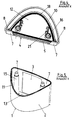
Figur 1- eine Vorderansicht auf eine Kennzeichenleuchte mit einer Abschlußscheibe, welche in einer Freimachung eines Abdeckteils angeordnet ist;
Figur 2- einen Schnitt nach der Linie A-A in
Figur 1; Figur 3- einen Schnitt nach der Linie B-B in
Figur 1; Figur 4- eine Ansicht aus Richtung X in das Innere des Abdeckteils;
Figur 5- eine Ansicht aus Richtung Y auf ein Gehäuseteil, auf welches das Abdeckteil aufgesetzt ist und
Figur 6- das Abdeckteil und das Gehäuseteil vor ihrem Zusammenbau.
- Figure 1
- a front view of a license plate light with a lens, which is arranged in an opening of a cover part;
- Figure 2
- a section along the line AA in Figure 1;
- Figure 3
- a section along the line BB in Figure 1;
- Figure 4
- a view from the direction X into the interior of the cover part;
- Figure 5
- a view from the direction Y of a housing part on which the cover part is placed and
- Figure 6
- the cover part and the housing part before their assembly.
Die Zeichnung zeigt eine Kennzeichenleuchte, welche mit einem Gehäuseteil (1) an einem Fahrzeug befestigbar ist. Das Gehäuseteil (1) weist eine Halteplatte (13) auf, welche an eine nicht dargestellte vertikale Fahrzeugfläche anlegbar ist und durch nicht dargestellte Befestigungsbolzen an dem Fahrzeug festsetzbar ist. In eine Öffnung der Halteplatte (13) ist eine aus elastischem Werkstoff bestehende Tülle (14) eingesetzt. Durch die Tülle (14) ist eine elektrische Leitung hindurchführbar. Das Gehäuseteil (1) weist an dem äußeren Rand der Halteplatte (13) eine umlaufende Seitenwand (2) auf. In einem eben ausgeführten Abschnitt ist die Seitenwand (2) von einer mit optischen Elementen besetzten Abschlußscheibe (3) komplettiert. Die Abschlußscheibe (3), die Seitenwand (2) und die Halteplatte (13) sind einstückig aus lichtdurchlässigem Kunststoff hergestellt. Die Abschlußscheibe (3) verläuft mit angrenzenden Bereichen (20) der Seitenwand (2) des Gehäuseteils (1) in einer Ebene, welche in einem stumpfen Winkel zur Halteplatte (13) steht. Der zwischen den Bereichen (20) verlaufende Abschnitt der Seitenwand (2) verläuft in Aufsetzrichtung (9) des Gehäuseteils (2) gesehen in einem ellipsenförmigen Bogen. Auf das Gehäuseteil (1) ist ein aus lichtundurchlässigem Kunststoff bestehenden Abdeckteil (4) mit einer annähernd in Aufsetzrichtung (9) gerichteten Seitenwand (6) aufgeschoben. Die Seitenwand (6) des Abdeckteils (4) erstreckt sich bis in die Fläche, in welcher die Halteplatte (13) verläuft. Die Seitenwand (6) des Abdeckteils (4) weist eine in Aufsetzrichtung (9) geöffnete Freimachung (5) für die Abschlußscheibe (3) auf, welche mit ihrer Hauptfläche annähernd parallel zur Aufsetzrichtung (9) verläuft. Die Abschlußscheibe (3) und die sie aufnehmende Freimachung (5) verjüngen sich mit ihren seitlichen Rändern (14) entgegen der Aufsetzrichtung (9). In die Freimachung (5) greift die erhaben ausgeführte Abschlußscheibe (3) ein und verläuft mit ihrer Außenseite bündig zu der Außenseite der angrenzenden Randabschnitt (7) der Seitenwand (6) des Abdeckteils (4). Die Randabschnitte (7) der Freimachung (5) verlaufen annähernd in der Ebene der Abschlußscheibe (3), während der an die Randabschnitte (7) angrenzende Abschnitt der Seitenwand (6) des Abdeckteils (4) in Aufsetzrichtung (9) gesehen in einem elliptischen Bogen verläuft. Der in einem elliptischen Bogen verlaufende Abschnitt der Seitenwand (6) des Abdeckteils (4) verjüngt das Abdeckteil (4) entgegen der Aufsetzrichtung (9) bis zu einer oberen Wand (12) des Abdeckteils (4). Die Innenseite des in einem Bogen verlaufenden Abschnitts der Seitenwand (6) des Abdeckteils (4) dient als Auflaufschräge (10) für den freien Rand (11) der Seitenwand (2) des Gehäuseteils (1). Die obere Wand (12) des Abdeckteils (4) weist an seinem inneren Randbereich ein u-förmiges Aufnahmebett (18) auf. Die äußere Wand des u-förmigen Aufnahmebetts (18) ist umlaufend von der Seitenwand (6) des Abdeckteils (4) gebildet, während die innere Wand an die Innenseite der oberen Wand (12) angeformt ist. In das u-förmige Aufnahmebett (18) ist umlaufend eine Dichtung eingesetzt, an welcher die Seitenwand (2) des Gehäuseteils (1) mit ihrem freien Rand (11) dicht anliegt. Die obere Wand (12) verläuft in einem spitzen Winkel (a) zu der in einer Ebene verlaufenden Abschlußscheibe (3), während die Seitenwand (6) des Abdeckteils (4) in einem spitzen Winkel (a) zu der Fläche der Halteplatte (13) und die Seitenwand (2) des Gehäuseteils (1) zumindest abschnittsweise in einem stumpfen Winkel (b) zur Fläche der Halteplatte (13) verläuft. An die Innenseite der oberen Wand (12) des Abdeckteils (4) sind Halteelemente (21) für eine Lampe (22) angebracht. An die Innenseite der Halteplatte (13) des Gehäuseteils (1) sind Befestigungsansätze (15) angeformt, welche sich entgegen der Aufsetzrichtung (9) zu Befestigungsöffnungen (16) hin erstrecken, welche in die obere Wand (12) des Abdeckteils (4) eingebracht sind. Durch die Befestigungsöffnungen (16) sind Befestigungsschrauben (23) mit ihrem Gewindeschaft hindurchgeführt und in den Befestigungsansatz (15) hineingedreht, bis der Kopf der Befestigungsschraube (23) dicht an der Außenseite des Abdeckteils (4) anliegt. Zwischen dem Kopf der Befestigungsschraube (23) und dem Abdeckteil (4) ist eine Dichtungsscheibe angeordnet. Beim Aufschieben der Seitenwand (6) des Abdeckteils (4) auf die Seitenwand (2) des Gehäuseteils (1) gleitet die Auflaufschräge (10) an dem freien Rand (11) der Seitenwand (2) des Gehäuseteils (1) entlang, bis der freie Rand (11) der Seitenwand (2) an dem Aufnahmebett (18) der oberen Wand (12) des Abdeckteils (4) anliegt. In dieser Lage des Abdeckteils (4) hat sich die Abschlußscheibe (3) selbsttätig in die Freimachung (5) des Abdeckteils (4) eingefädelt und die an die Abschlußscheibe (3) heranführenden Bereiche (20) der Seitenwand (6) des Abdeckteils (4) liegen an der Anlagefläche (8) der Randabschnitte (7) der Freimachung (5) an. The drawing shows a license plate light, which with a housing part (1) is attachable to a vehicle. The housing part (1) has a holding plate (13), which can be applied to a vertical vehicle surface, not shown, and by Fastening bolts, not shown, can be fixed on the vehicle. In a Opening of the holding plate (13) is a spout made of elastic material (14) used. An electrical line can be passed through the grommet (14). The housing part (1) has a on the outer edge of the holding plate (13) peripheral side wall (2). In a section just executed is the Side wall (2) of a lens (3) with optical elements completed. The cover plate (3), the side wall (2) and the holding plate (13) are made in one piece from translucent plastic. The lens (3) runs with adjacent areas (20) of the side wall (2) of the housing part (1) in a plane which is at an obtuse angle to the holding plate (13). Of the section of the side wall (2) running between the regions (20) runs in Positioning direction (9) of the housing part (2) seen in an elliptical arc. On the housing part (1) is made of an opaque plastic Cover part (4) with a side wall (6) oriented approximately in the mounting direction (9) postponed. The side wall (6) of the cover part (4) extends into the Area in which the holding plate (13) runs. The side wall (6) of the cover part (4) has a franking (5) open in the mounting direction (9) for the End plate (3), which with its main surface approximately parallel to Setting direction (9). The lens (3) and the receiving Franking (5) taper with their side edges (14) against the Touch direction (9). The raised version reaches into the franking (5) End plate (3) and is flush with the outside to the outside the adjacent edge section (7) of the side wall (6) of the cover part (4). The Edge sections (7) of the franking (5) run approximately in the plane of the End plate (3), while the portion adjacent to the edge portions (7) the side wall (6) of the cover part (4) in the mounting direction (9) seen in one elliptical arc. The section running in an elliptical arc the side wall (6) of the cover part (4) tapers the cover part (4) against Positioning direction (9) up to an upper wall (12) of the cover part (4). The Inside of the arcuate section of the side wall (6) of the Cover part (4) serves as a ramp (10) for the free edge (11) Side wall (2) of the housing part (1). The upper wall (12) of the cover part (4) has a U-shaped receiving bed (18) on its inner edge region. The outer Wall of the U-shaped receiving bed (18) is circumferential from the side wall (6) of the Cover part (4) formed, while the inner wall to the inside of the upper Wall (12) is integrally formed. In the U-shaped receiving bed (18) is all around Seal used, on which the side wall (2) of the housing part (1) with its free edge (11) lies tight. The upper wall (12) runs at an acute angle (a) to the in-plane lens (3), while the Side wall (6) of the cover part (4) at an acute angle (a) to the surface of the Holding plate (13) and the side wall (2) of the housing part (1) at least in sections at an obtuse angle (b) to the surface of the holding plate (13) runs. On the inside of the top wall (12) of the cover part (4) Holding elements (21) for a lamp (22) attached. To the inside of the Retaining plate (13) of the housing part (1) are molded on attachment lugs (15), which are opposite to the mounting direction (9) towards fastening openings (16) extend which are introduced into the upper wall (12) of the cover part (4). Through the mounting holes (16) are mounting screws (23) with your Threaded shaft passed through and screwed into the fastening projection (15), until the head of the fastening screw (23) is close to the outside of the cover part (4) is present. Between the head of the fastening screw (23) and the cover part (4) a sealing washer is arranged. When sliding the side wall (6) of the Cover part (4) on the side wall (2) of the housing part (1) slides Run-up slope (10) on the free edge (11) of the side wall (2) of the housing part (1) along until the free edge (11) of the side wall (2) on the receiving bed (18) the upper wall (12) of the cover part (4) abuts. In this position of the cover part (4) the lens (3) automatically in the franking (5) of the Cover part (4) threaded and leading to the lens (3) Areas (20) of the side wall (6) of the cover part (4) lie on the contact surface (8) of the edge sections (7) of the franking (5).
- 11
- GehäuseteilHousing part
- 22nd
- Seitenwand des GehäuseteilsSide wall of the housing part
- 33rd
- AbschlußscheibeCover lens
- 44th
- AbdeckteilCover part
- 55
- FreimachungFranking
- 66
- Seitenwand des AbdeckteilsSide wall of the cover part
- 77
- Randabschnitte der FreimachungMarginal sections of the franking
- 88th
- AnlageflächeContact surface
- 99
- AufsetzrichtungDirection of touchdown
- 1010th
- AuflaufschrägeRamp
- 1111
- Randedge
- 1212th
- Wandwall
- 1313
- HalteplatteRetaining plate
- 1414
- RänderEdges
- 1515
- BefestigungsansatzAttachment approach
- 1616
- BefestigungsöffnungMounting hole
- 1717th
- Lampelamp
- 1818th
- AufnahmebettExtra bed
- 1919th
- Tüllegrommet
- 2020th
- BereicheAreas
- 2121
- HalteelementHolding element
- 2222
- Lampelamp
- 2323
- BefestigungsschraubenMounting screws
Claims (13)
Applications Claiming Priority (2)
| Application Number | Priority Date | Filing Date | Title |
|---|---|---|---|
| DE19638063A DE19638063A1 (en) | 1996-09-18 | 1996-09-18 | Light for vehicles, in particular license plate light for vehicles |
| DE19638063 | 1996-09-18 |
Publications (3)
| Publication Number | Publication Date |
|---|---|
| EP0830983A2 true EP0830983A2 (en) | 1998-03-25 |
| EP0830983A3 EP0830983A3 (en) | 1999-03-03 |
| EP0830983B1 EP0830983B1 (en) | 2002-04-17 |
Family
ID=7806018
Family Applications (1)
| Application Number | Title | Priority Date | Filing Date |
|---|---|---|---|
| EP97115321A Expired - Lifetime EP0830983B1 (en) | 1996-09-18 | 1997-09-04 | Vehicle light |
Country Status (3)
| Country | Link |
|---|---|
| EP (1) | EP0830983B1 (en) |
| DE (2) | DE19638063A1 (en) |
| ES (1) | ES2175237T3 (en) |
Families Citing this family (1)
| Publication number | Priority date | Publication date | Assignee | Title |
|---|---|---|---|---|
| FI110079B (en) * | 1997-10-17 | 2002-11-29 | Talmu Ab Oy | Lantern |
Citations (1)
| Publication number | Priority date | Publication date | Assignee | Title |
|---|---|---|---|---|
| DE3836032A1 (en) | 1988-10-22 | 1990-04-26 | Hella Kg Hueck & Co | Light for motor vehicles |
Family Cites Families (7)
| Publication number | Priority date | Publication date | Assignee | Title |
|---|---|---|---|---|
| BE423050A (en) * | ||||
| IT1128924B (en) * | 1980-07-10 | 1986-06-04 | Iao Industrie Riunite Spa | OPTICAL GROUP FOR VEHICLES |
| US4506314A (en) * | 1983-09-21 | 1985-03-19 | Moore Dennis G | Submersible signal lamp with interchangeable lens assembly |
| US5157377A (en) * | 1987-01-20 | 1992-10-20 | Mark Wayne | Hood scoop assembly |
| DE3723029C2 (en) * | 1987-07-11 | 1994-06-30 | Hella Kg Hueck & Co | Multi-chamber light with a license plate holder |
| DE4137612C1 (en) * | 1991-11-15 | 1993-05-06 | Hella Kg Hueck & Co, 4780 Lippstadt, De | |
| ES2088174T3 (en) * | 1992-03-03 | 1996-08-01 | Hella Kg Hueck & Co | LAMP FOR VEHICLES. |
-
1996
- 1996-09-18 DE DE19638063A patent/DE19638063A1/en not_active Withdrawn
-
1997
- 1997-09-04 EP EP97115321A patent/EP0830983B1/en not_active Expired - Lifetime
- 1997-09-04 ES ES97115321T patent/ES2175237T3/en not_active Expired - Lifetime
- 1997-09-04 DE DE59707022T patent/DE59707022D1/en not_active Expired - Lifetime
Patent Citations (1)
| Publication number | Priority date | Publication date | Assignee | Title |
|---|---|---|---|---|
| DE3836032A1 (en) | 1988-10-22 | 1990-04-26 | Hella Kg Hueck & Co | Light for motor vehicles |
Also Published As
| Publication number | Publication date |
|---|---|
| DE59707022D1 (en) | 2002-05-23 |
| ES2175237T3 (en) | 2002-11-16 |
| EP0830983B1 (en) | 2002-04-17 |
| EP0830983A3 (en) | 1999-03-03 |
| DE19638063A1 (en) | 1998-03-19 |
Similar Documents
| Publication | Publication Date | Title |
|---|---|---|
| EP2832497B1 (en) | Manually operated work device | |
| DE102004035379B4 (en) | Filter with support columns | |
| EP0175121A1 (en) | Instrument panel for motor vehicles | |
| DE3512882C2 (en) | ||
| DE3902229A1 (en) | HEADLIGHT | |
| DE10010722A1 (en) | Sealing unit for a steering column passing through the separation wall of a motor vehicle comprises a rigid protective plate which is positioned in front of the rubber elastic sealing element | |
| DE602004005628T2 (en) | Bracket with several bridges | |
| DE2819336C3 (en) | Device for captive securing of a screw part | |
| WO1999037502A1 (en) | Light for vehicles, especially rear light for vehicles | |
| EP0830983B1 (en) | Vehicle light | |
| DE4024313A1 (en) | REINFORCED STRUCTURE OF THE COMBUSTION ENGINE CYLINDER BLOCK | |
| EP0888954A1 (en) | Plastic closure cap | |
| DE4204028B4 (en) | wheel cylinder | |
| EP0299151B1 (en) | Multiple lights with a support for a licence plate | |
| WO2004084342A1 (en) | Antenna comprising a plastic housing | |
| DE10217420B4 (en) | Device for connecting a headlamp to a vehicle body | |
| DE3346383C1 (en) | Two-part air-filter housing | |
| DE4126112C1 (en) | ||
| EP0838369A2 (en) | Fixation device for vehicle lights or headlamps | |
| DE4320330C2 (en) | Sealing device for a frameless window of a motor vehicle | |
| DE19522669C2 (en) | Housing of a light-generating device for motor vehicles | |
| DE2914959C2 (en) | Auxiliary headlights for motor vehicles | |
| DE19513369A1 (en) | Lighting device for vehicles | |
| DE19716736A1 (en) | Device for mounting the sensor | |
| EP0679552A2 (en) | Cover for lighting unit with reflectors |
Legal Events
| Date | Code | Title | Description |
|---|---|---|---|
| PUAI | Public reference made under article 153(3) epc to a published international application that has entered the european phase |
Free format text: ORIGINAL CODE: 0009012 |
|
| AK | Designated contracting states |
Kind code of ref document: A2 Designated state(s): DE ES FR GB IT |
|
| AX | Request for extension of the european patent |
Free format text: AL;LT;LV;RO;SI |
|
| PUAL | Search report despatched |
Free format text: ORIGINAL CODE: 0009013 |
|
| AK | Designated contracting states |
Kind code of ref document: A3 Designated state(s): AT BE CH DE DK ES FI FR GB GR IE IT LI LU MC NL PT SE |
|
| AX | Request for extension of the european patent |
Free format text: AL;LT;LV;RO;SI |
|
| 17P | Request for examination filed |
Effective date: 19990707 |
|
| AKX | Designation fees paid |
Free format text: DE ES FR GB IT |
|
| GRAG | Despatch of communication of intention to grant |
Free format text: ORIGINAL CODE: EPIDOS AGRA |
|
| 17Q | First examination report despatched |
Effective date: 20010530 |
|
| GRAG | Despatch of communication of intention to grant |
Free format text: ORIGINAL CODE: EPIDOS AGRA |
|
| GRAH | Despatch of communication of intention to grant a patent |
Free format text: ORIGINAL CODE: EPIDOS IGRA |
|
| REG | Reference to a national code |
Ref country code: GB Ref legal event code: IF02 |
|
| GRAH | Despatch of communication of intention to grant a patent |
Free format text: ORIGINAL CODE: EPIDOS IGRA |
|
| GRAA | (expected) grant |
Free format text: ORIGINAL CODE: 0009210 |
|
| AK | Designated contracting states |
Kind code of ref document: B1 Designated state(s): DE ES FR GB IT |
|
| PG25 | Lapsed in a contracting state [announced via postgrant information from national office to epo] |
Ref country code: GB Free format text: LAPSE BECAUSE OF FAILURE TO SUBMIT A TRANSLATION OF THE DESCRIPTION OR TO PAY THE FEE WITHIN THE PRESCRIBED TIME-LIMIT Effective date: 20020417 |
|
| REF | Corresponds to: |
Ref document number: 59707022 Country of ref document: DE Date of ref document: 20020523 |
|
| ET | Fr: translation filed | ||
| GBV | Gb: ep patent (uk) treated as always having been void in accordance with gb section 77(7)/1977 [no translation filed] |
Effective date: 20020417 |
|
| REG | Reference to a national code |
Ref country code: ES Ref legal event code: FG2A Ref document number: 2175237 Country of ref document: ES Kind code of ref document: T3 |
|
| PLBE | No opposition filed within time limit |
Free format text: ORIGINAL CODE: 0009261 |
|
| STAA | Information on the status of an ep patent application or granted ep patent |
Free format text: STATUS: NO OPPOSITION FILED WITHIN TIME LIMIT |
|
| 26N | No opposition filed |
Effective date: 20030120 |
|
| PGFP | Annual fee paid to national office [announced via postgrant information from national office to epo] |
Ref country code: IT Payment date: 20060930 Year of fee payment: 10 |
|
| PG25 | Lapsed in a contracting state [announced via postgrant information from national office to epo] |
Ref country code: IT Free format text: LAPSE BECAUSE OF NON-PAYMENT OF DUE FEES Effective date: 20070904 |
|
| PGFP | Annual fee paid to national office [announced via postgrant information from national office to epo] |
Ref country code: FR Payment date: 20120926 Year of fee payment: 16 |
|
| PGFP | Annual fee paid to national office [announced via postgrant information from national office to epo] |
Ref country code: ES Payment date: 20121004 Year of fee payment: 16 |
|
| REG | Reference to a national code |
Ref country code: DE Ref legal event code: R084 Ref document number: 59707022 Country of ref document: DE Effective date: 20130606 |
|
| REG | Reference to a national code |
Ref country code: FR Ref legal event code: ST Effective date: 20140530 |
|
| PG25 | Lapsed in a contracting state [announced via postgrant information from national office to epo] |
Ref country code: FR Free format text: LAPSE BECAUSE OF NON-PAYMENT OF DUE FEES Effective date: 20130930 |
|
| REG | Reference to a national code |
Ref country code: ES Ref legal event code: FD2A Effective date: 20141007 |
|
| PG25 | Lapsed in a contracting state [announced via postgrant information from national office to epo] |
Ref country code: ES Free format text: LAPSE BECAUSE OF NON-PAYMENT OF DUE FEES Effective date: 20130905 |
|
| PGFP | Annual fee paid to national office [announced via postgrant information from national office to epo] |
Ref country code: DE Payment date: 20160831 Year of fee payment: 20 |
|
| REG | Reference to a national code |
Ref country code: DE Ref legal event code: R071 Ref document number: 59707022 Country of ref document: DE |