EP0830212B1 - Apparatus for electrostatically depositing and retaining materials upon a substrate - Google Patents
Apparatus for electrostatically depositing and retaining materials upon a substrate Download PDFInfo
- Publication number
- EP0830212B1 EP0830212B1 EP96921360A EP96921360A EP0830212B1 EP 0830212 B1 EP0830212 B1 EP 0830212B1 EP 96921360 A EP96921360 A EP 96921360A EP 96921360 A EP96921360 A EP 96921360A EP 0830212 B1 EP0830212 B1 EP 0830212B1
- Authority
- EP
- European Patent Office
- Prior art keywords
- trace
- collection
- dielectric layer
- charge
- charging
- Prior art date
- Legal status (The legal status is an assumption and is not a legal conclusion. Google has not performed a legal analysis and makes no representation as to the accuracy of the status listed.)
- Expired - Lifetime
Links
- 239000000463 material Substances 0.000 title claims abstract description 69
- 239000000758 substrate Substances 0.000 title claims abstract description 63
- 238000000151 deposition Methods 0.000 title claims description 42
- 230000008021 deposition Effects 0.000 claims abstract description 39
- 239000003814 drug Substances 0.000 claims description 44
- 239000000843 powder Substances 0.000 claims description 30
- 239000007788 liquid Substances 0.000 claims description 15
- 238000000034 method Methods 0.000 claims description 14
- 239000002245 particle Substances 0.000 claims description 11
- 230000000717 retained effect Effects 0.000 claims description 9
- 239000011159 matrix material Substances 0.000 claims description 4
- 239000000126 substance Substances 0.000 claims 1
- 238000007747 plating Methods 0.000 abstract description 7
- 229940079593 drug Drugs 0.000 description 6
- 239000011248 coating agent Substances 0.000 description 4
- 238000000576 coating method Methods 0.000 description 4
- 238000004040 coloring Methods 0.000 description 4
- 239000012530 fluid Substances 0.000 description 4
- 239000004020 conductor Substances 0.000 description 3
- 150000002500 ions Chemical class 0.000 description 3
- 239000000123 paper Substances 0.000 description 3
- 230000002596 correlated effect Effects 0.000 description 2
- 238000007599 discharging Methods 0.000 description 2
- 210000004072 lung Anatomy 0.000 description 2
- 230000014759 maintenance of location Effects 0.000 description 2
- 238000010521 absorption reaction Methods 0.000 description 1
- PNEYBMLMFCGWSK-UHFFFAOYSA-N aluminium oxide Inorganic materials [O-2].[O-2].[O-2].[Al+3].[Al+3] PNEYBMLMFCGWSK-UHFFFAOYSA-N 0.000 description 1
- 239000011111 cardboard Substances 0.000 description 1
- 239000002801 charged material Substances 0.000 description 1
- 239000003989 dielectric material Substances 0.000 description 1
- 238000004924 electrostatic deposition Methods 0.000 description 1
- 230000005686 electrostatic field Effects 0.000 description 1
- 239000004744 fabric Substances 0.000 description 1
- 239000012212 insulator Substances 0.000 description 1
- 230000003252 repetitive effect Effects 0.000 description 1
- 238000000427 thin-film deposition Methods 0.000 description 1
- 229910021654 trace metal Inorganic materials 0.000 description 1
Images

Classifications
-
- B—PERFORMING OPERATIONS; TRANSPORTING
- B05—SPRAYING OR ATOMISING IN GENERAL; APPLYING FLUENT MATERIALS TO SURFACES, IN GENERAL
- B05B—SPRAYING APPARATUS; ATOMISING APPARATUS; NOZZLES
- B05B5/00—Electrostatic spraying apparatus; Spraying apparatus with means for charging the spray electrically; Apparatus for spraying liquids or other fluent materials by other electric means
- B05B5/025—Discharge apparatus, e.g. electrostatic spray guns
-
- G—PHYSICS
- G03—PHOTOGRAPHY; CINEMATOGRAPHY; ANALOGOUS TECHNIQUES USING WAVES OTHER THAN OPTICAL WAVES; ELECTROGRAPHY; HOLOGRAPHY
- G03G—ELECTROGRAPHY; ELECTROPHOTOGRAPHY; MAGNETOGRAPHY
- G03G17/00—Electrographic processes using patterns other than charge patterns, e.g. an electric conductivity pattern; Processes involving a migration, e.g. photoelectrophoresis, photoelectrosolography; Processes involving a selective transfer, e.g. electrophoto-adhesive processes; Apparatus essentially involving a single such process
-
- A—HUMAN NECESSITIES
- A61—MEDICAL OR VETERINARY SCIENCE; HYGIENE
- A61M—DEVICES FOR INTRODUCING MEDIA INTO, OR ONTO, THE BODY; DEVICES FOR TRANSDUCING BODY MEDIA OR FOR TAKING MEDIA FROM THE BODY; DEVICES FOR PRODUCING OR ENDING SLEEP OR STUPOR
- A61M15/00—Inhalators
- A61M15/0028—Inhalators using prepacked dosages, one for each application, e.g. capsules to be perforated or broken-up
- A61M15/0045—Inhalators using prepacked dosages, one for each application, e.g. capsules to be perforated or broken-up using multiple prepacked dosages on a same carrier, e.g. blisters
- A61M15/0046—Inhalators using prepacked dosages, one for each application, e.g. capsules to be perforated or broken-up using multiple prepacked dosages on a same carrier, e.g. blisters characterized by the type of carrier
- A61M15/0048—Inhalators using prepacked dosages, one for each application, e.g. capsules to be perforated or broken-up using multiple prepacked dosages on a same carrier, e.g. blisters characterized by the type of carrier the dosages being arranged in a plane, e.g. on diskettes
-
- A—HUMAN NECESSITIES
- A61—MEDICAL OR VETERINARY SCIENCE; HYGIENE
- A61M—DEVICES FOR INTRODUCING MEDIA INTO, OR ONTO, THE BODY; DEVICES FOR TRANSDUCING BODY MEDIA OR FOR TAKING MEDIA FROM THE BODY; DEVICES FOR PRODUCING OR ENDING SLEEP OR STUPOR
- A61M15/00—Inhalators
- A61M15/02—Inhalators with activated or ionised fluids, e.g. electrohydrodynamic [EHD] or electrostatic devices; Ozone-inhalators with radioactive tagged particles
- A61M15/025—Bubble jet droplet ejection devices
-
- B—PERFORMING OPERATIONS; TRANSPORTING
- B05—SPRAYING OR ATOMISING IN GENERAL; APPLYING FLUENT MATERIALS TO SURFACES, IN GENERAL
- B05B—SPRAYING APPARATUS; ATOMISING APPARATUS; NOZZLES
- B05B12/00—Arrangements for controlling delivery; Arrangements for controlling the spray area
- B05B12/16—Arrangements for controlling delivery; Arrangements for controlling the spray area for controlling the spray area
-
- B—PERFORMING OPERATIONS; TRANSPORTING
- B05—SPRAYING OR ATOMISING IN GENERAL; APPLYING FLUENT MATERIALS TO SURFACES, IN GENERAL
- B05B—SPRAYING APPARATUS; ATOMISING APPARATUS; NOZZLES
- B05B5/00—Electrostatic spraying apparatus; Spraying apparatus with means for charging the spray electrically; Apparatus for spraying liquids or other fluent materials by other electric means
- B05B5/08—Plant for applying liquids or other fluent materials to objects
-
- B—PERFORMING OPERATIONS; TRANSPORTING
- B41—PRINTING; LINING MACHINES; TYPEWRITERS; STAMPS
- B41J—TYPEWRITERS; SELECTIVE PRINTING MECHANISMS, i.e. MECHANISMS PRINTING OTHERWISE THAN FROM A FORME; CORRECTION OF TYPOGRAPHICAL ERRORS
- B41J2/00—Typewriters or selective printing mechanisms characterised by the printing or marking process for which they are designed
- B41J2/385—Typewriters or selective printing mechanisms characterised by the printing or marking process for which they are designed characterised by selective supply of electric current or selective application of magnetism to a printing or impression-transfer material
- B41J2/41—Typewriters or selective printing mechanisms characterised by the printing or marking process for which they are designed characterised by selective supply of electric current or selective application of magnetism to a printing or impression-transfer material for electrostatic printing
- B41J2/415—Typewriters or selective printing mechanisms characterised by the printing or marking process for which they are designed characterised by selective supply of electric current or selective application of magnetism to a printing or impression-transfer material for electrostatic printing by passing charged particles through a hole or a slit
- B41J2/4155—Typewriters or selective printing mechanisms characterised by the printing or marking process for which they are designed characterised by selective supply of electric current or selective application of magnetism to a printing or impression-transfer material for electrostatic printing by passing charged particles through a hole or a slit for direct electrostatic printing [DEP]
-
- A—HUMAN NECESSITIES
- A61—MEDICAL OR VETERINARY SCIENCE; HYGIENE
- A61M—DEVICES FOR INTRODUCING MEDIA INTO, OR ONTO, THE BODY; DEVICES FOR TRANSDUCING BODY MEDIA OR FOR TAKING MEDIA FROM THE BODY; DEVICES FOR PRODUCING OR ENDING SLEEP OR STUPOR
- A61M15/00—Inhalators
- A61M15/02—Inhalators with activated or ionised fluids, e.g. electrohydrodynamic [EHD] or electrostatic devices; Ozone-inhalators with radioactive tagged particles
Definitions
- the invention relates to electrostatic material deposition techniques and, more particularly to a substrate containing electrodes that provide electrostatic fields for retention of various materials upon the substrate.
- US-A-2 408 143 proposes an apparatus for printing, which applies ink or other colouring fluids to the successive image areas only of a movable image carrying member by electrostatic or electronographic and/or magnetic lines of force created by one electrical circuit and then transferring the same from said successive image areas to correlated successive areas of the print receiving material by electrostatic or electronographic and/or magnetic lines of force created by a second and separate electric circuit.
- the moveable image carrying member is electrically insulated from both electrical circuits and is provided with image areas that are permeable to lines of force and non-image areas which are impermeable thereto. This may be accomplished by coating the non-image areas with suitable material that is impermeable to lines of force while leaving the image areas free of said coating material. Then the ink or other colouring fluid is transferred by the lines of force created by the first electrical circuit from an ink discharging element to the image areas only of the image carrying member.
- the ink discharging element cooperates with an ink attraction element electrically connected in circuit with it but separated from the discharge element by the movable image carrying member.
- the ink or other colouring fluid which is deposited on the image areas only of the movable image carrying member is then transferred from said areas to correlated successive areas of the print receiving material by lines of force created by the second and separate electric circuit.
- the print receiving material passes between the image carrying member and supporting member and is supported by the latter.
- a repulsion element or blade is operatively associated with the image carrying member and an attraction element or blade is operatively associated with the supporting member, with said elements or blades electrically connected in the second and separate electric circuit but separated by the supporting member, the print receiving material and the image carrying member, wherefore lines of force passing across the gap between said blades pass through both members and the print receiving material.
- the supporting member may also have operatively associated therewith magnets for creating a magnetic field of force extending through both members and the print receiving material and acting to transfer the ink or colouring fluid from the image areas to the successive areas of said material.
- Electrostatic deposition of materials such as toner powders is typically accomplished using an ion gun or print head to deposit a charge pattern upon a dielectric substrate.
- the print head scans a dielectric substrate and selectively deposits on the substrate a pattern of charge.
- the charge pattern is then exposed to a cloud of oppositely charged powder particles and the charge pattern attracts the powder to the substrate.
- the powder adheres to the substrate via electrostatic forces between the charged substrate and the oppositely charged powder.
- the substrate e.g., paper
- the substrate e.g., paper
- the systems mechanically scan the head over the substrate to produce an accurate charge pattern.
- Such mechanical scanning requires a complicated head scanning mechanism.
- Such a mechanism is generally required where the pattern is constantly changing from one printing job to the next, e.g., systems that print text or graphics.
- other printing applications require repeated deposition of a particular charge quantity in a predefined pattern.
- Such an application includes retention of powdered drugs (medicament) at predefined locations on a substrate that is a component of a medication inhaler.
- Another such application is a printing stamp requiring a repeated pattern to be generated with each use of the stamp.
- apparatus for electrostatically retaining a deposition material comprising:
- a method of electrostatically depositing a dose of medicament comprising the steps of:
- apparatus for electrostatically retaining a deposition material comprising:
- an embodiment of the present invention provides a substrate having a planar conductive plating located on a first surface of a dielectric layer and having a conductive trace (a collection trace) located on a second surface of the dielectric layer such that the conductive plating and the conductive trace have a parallel, spaced-apart relation with respect to one another.
- the conductive trace is charged by supplying a voltage to both the plating and the trace to establish a voltage differential across the dielectric layer. As such, depending upon the magnitude of the voltage, polarity of the voltage and the duration for which the voltage is applied to the trace, a particular quantity and polarity of charge accumulates on the trace.
- the material to be deposited is charged to an opposite polarity than that of the trace and then the deposition material is applied to the trace.
- the deposition material is a powder, such as a powdered medicament
- the powder is charged in a tribo-electric charging gun.
- the material is a liquid, such as an ink
- the liquid is charged using corona discharge apparatus within a liquid atomizer. In either case, the charged material is disposed over the charged collection trace and is electrostatically attracted to the trace. As such, the material adheres to the trace.
- the quantity of material adhered is directly proportional to the charge on the trace and the charge-to-mass ratio of the particles of deposition material. By determining the charge accumulated on the trace and the charge-to-mass ratio, a specific and repeatable quantity of deposition material is retained by the substrate.
- the present invention provides a cost effective apparatus for repeatedly generating a well-defined charge pattern without using a robotically scanned print head.
- Applications for such apparatus include a substrate for retaining dry powder drugs within a drug inhaler and a substrate for retaining ink or toner in a programmable printing stamp.
- the present invention is apparatus for electrostatically retaining a deposition material upon a substrate.
- the apparatus contains a conductive plate, a dielectric layer located upon the plate, and a conductive trace located upon the dielectric layer in a parallel spaced-apart relation with respect to the conductive plate.
- a voltage is temporarily applied between the plate and the trace to charge the trace.
- deposition material having a charge opposite that of the charge on the trace, is disposed upon the charged trace.
- the charged deposition material is attracted to the charged trace and is electrostatically adhered thereto.
- the apparatus utilizes a relatively simple technique for electrostatically retaining the deposition material without using a mechanically scanned print head to form a charge pattern in the substrate.
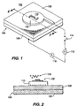
- FIG. 1 depicts a perspective view of the invention
- FIG. 2 depicts a cross-sectional view of a substrate 104 along line 2-2 of FIG. 1.
- the reader should consult both FIG. 1 and 2 while reading the following detailed description of the invention.
- Apparatus 100 is designed to electrostatically retain a predefined quantity of deposition material 102 within a well-defined area upon a substrate 104.
- the apparatus contains the substrate 104, a voltage source 112, an ammeter 118, and a switch 114.
- the substrate 104 contains a conductive plate 106 and a conducive trace 110 (also referred to herein as a collection trace) separated from said conductive plate by a dielectric layer 108.
- the dielectric layer is typically alumina of thickness 5 micrometers.
- the conductors are typically created using a conventional thin film deposition process.
- the collection trace 110 and plate 106 have a parallel spaced-apart relation with respect to one another.
- One terminal of a DC voltage source 112 is connected, through switch 114, to trace 110.
- the other terminal of source 112 is connected through ammeter 118 to plate 106.
- the voltage source charges the collection trace with respect to the plate.
- the amount of charge accumulated on the trace during a specific period of time is directly proportional to the voltage differential applied between the plate and trace, i.e., the larger the differential, the greater the accumulated charge during a given time period.
- the current magnitude indicated by the ammeter 118 is monitored to determine a quantity of charge accumulated on the plate during a specified period of time that the switch is closed.
- the trace is connected to the positive terminal of the source and the negative terminal of the source (ground) is connected to the plate.
- the trace upon closure of the switch, the trace is charged positively with respect to the plate.
- the plate could be charged negatively with respect to the plate without detrimentally affecting the operation of the inventive apparatus.
- the voltage used to charge the trace is a relatively low voltage, i.e., the voltage is typically on the order of tens to hundreds of volts.
- the capacitance between the trace and the plate is approximately 5 pF. With such a capacitance, the time required to charge the plate is approximately 50 picoseconds.
- the charge duration can be increased by adding a series resistor between the plate and the voltage source.
- a deposition material 116 is disposed over the charged collection trace.
- the material 116 is either a powder, such as a medicament or a printing toner, or a liquid, such as a printing ink. Whether a powder or a liquid is used, the material is electrically charged before being disposed over the trace. To facilitate electrostatic attraction between the material and the trace, the charge on the material is opposite the charge on the trace.
- a powder deposition material is charged using a conventional tribo-electric charging technique (e.g., using what is commonly known as a tribo-electric charging gun) that provides a substantially uniform charge-to-mass ratio on the powder particles.
- the powder is charged at an opposite polarity to the charge on the trace.
- the powder is expelled from the tribo-electric charging gun by a flow of air or some other gas.
- the expelled powder forms a cloud of charged powder particles proximate the charged collection trace.
- the trace attracts and retains the charged powder.
- the amount of powder that accumulates on the trace is directly proportional to the charge density on the trace.
- the dimensions of the trace define an area in which the powder is retained. Consequently, using the invention, a particular location on a substrate retains a particular amount of powder.
- the liquid is typically charged by conventional corona charging apparatus within a liquid atomizer device.
- the liquid is typically charged as it is atomized within the atomizer.
- the atomizer expels the atomized liquid proximate to the charged collection trace.
- the trace attracts and retains the charged liquid.
- the particular dimensions of the trace define an area in which the liquid is retained.
- the substrate surface including the collection trace
- a dielectric material such coating is typically required to ensure that the collection trace metal or the dielectric layer material of the substrate do not chemically react with the deposition material.
- a coating of this type should have little or no impact upon the operation and usefulness of the invention as described herein.
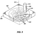
- FIG. 3 depicts a specific application for the invention.
- the apparatus of FIG. 3 is a dry powder drug (medicament) inhaler 300 that is designed to retain a dry powdered drug at specific locations upon a substrate 302.
- a powdered medicament is deposited in well defined doses in the manner discussed above and retained at particular locations upon the substrate until removed by an external force.
- the collection traces 304 that define the location and area upon which the medicament is retained typically have a diameter of 1 ⁇ 02 mm (.040 inches).
- a plurality of circular collection traces 304 are located on the substrate 302 to enable multiple doses of the medicament to be retained in well-defined locations upon a single substrate.
- a housing 306 encloses the substrate 302 and supports a flexible delivery tube 308.
- the substrate is rotatable about a central axis 314 with respect to the housing and the delivery tube. As such, the substrate can be rotated to align a particular medicament dose (i.e., a particular collection trace) with an inlet end 310 of the delivery tube 308.
- a particular medicament dose i.e., a particular collection trace
- the substrate at each of the trace locations is perforated with a plurality of openings that are smaller than the smallest medicament particle. As such, air flows through the dose location, i.e., through perforations in the collection trace, the dielectric layer and the plate, to carry the medicament to the patient.
- FIG. 4 depicts a perspective view of another embodiment of the inventive substrate for utilization in a dry powder medicament inhaler such as the inhaler of FIG. 3.
- FIG. 5 depicts a cross-sectional view of the substrate in FIG. 4 taken along line 5-5. To best understand this embodiment of the invention, the reader should consult both FIGS. 4 and 5 while reading the following detailed description.
- Apparatus 400 contains substrate 402, charging plate 404, an ammeter 405, and voltage source 406.
- Each medicament dose location contains an opening 408 through a dielectric layer 410.
- the opening has deposited therein a collection trace 412 that plates the surface of the opening as well as an area on a top surface 414 of the dielectric layer 410.
- Underlying the entire dielectric layer 410 is a conductive plate 416.
- the plate contains apertures 418 that are coaxial with, but slightly larger in diameter than, the openings 408 through the dielectric layer 410.
- the apparatus contains a charging plate 404 fabricated of a conductive material and having a plurality of cone-shaped protuberances 420.
- the protuberances are aligned with the respective openings 408 and 418 in the dielectric layer 410 and the conductive plate 416.
- the protuberances are sized to enter the openings 408 in the dielectric layer and contact the trace plating 412 within each opening 408 without contacting the conductive plate 416.
- the charging plate is connected to one terminal of a DC voltage source 406 and the conductive plate is connected through an ammeter to the other terminal of the source. As such, when a protuberance of the charging plate contacts the collection trace, a charge accumulates on the trace. Such charging is accomplished by moving the charging plate upwards in a direction indicated by arrow 422. The charge accumulated is directly proportional to the voltage applied between the trace and the conductive plate. Once a particular charge is accumulated, the charging plate is removed from contact with the collection trace by moving the charging plate downwards in a direction indicated by arrow 424.
- a cloud of charged medicament is generated proximate the collection traces.
- the trace retains the medicament in a quantity that is proportional to the accumulated charge on the collection trace.
- the location and quantity (dose) of the medicament dose is strictly controlled.
- the substrate 402 is used in an inhaler such as that described with respect to FIG. 3.
- an inhaler such as that described with respect to FIG. 3.
- air flow passes through the opening 408 in the dielectric layer 410 and dislodges the medicament from the trace 412.
- the airflow carries the dislodged medicament powder to the patient's lungs.
- FIG. 6 depicts another alternative embodiment of the present invention that permits each collection trace to be selectively and individually charged.
- the substrate 616 contains the collection traces 412 shown in FIG. 5 arranged in an array 602 upon a dielectric layer 600.
- the traces for this embodiment may or may not have an opening extending through the trace, i.e., the opening 408 may be filled with conductive material that comprises the collection trace 412.
- the charging plate 604, in the embodiment of FIG. 6, is fabricated of an insulator having a plurality of conductive protuberances 606 deposited upon its surface.
- the protuberances are connected to conductive traces 608 that lead to an edge connector 610 located at one edge of the charging plate.
- Each protuberance 606 is aligned with an associated collection trace 412 of the substrate 616.
- one terminal of a DC voltage source 612 is connected to the conductive plate 61 of the substrate, while the other terminal is connected, through an ammeter 618, to selected ones of the protuberances 606.
- Switching logic 614 such as programmable array logic (PAL), is used to select the protuberances that are to be connected to the voltage source.
- the charging plate is moved upwards along arrow 620 into contact with the substrate such that each of the protuberances 606 contact their associated collection trace 412.
- the protuberances that are selectively connected to the voltage source 612 facilitate charging of their respective collection traces.
- a deposition material is deposited on the collection traces.
- a powder such as a printing toner
- a liquid such as a printing ink
- the charged deposition material adheres to only those collection traces that are charged.
- the material adheres in a pattern defined by the collection traces that are charged.
- the traces coated with deposition material can be used in various applications such as repetitive printing onto paper or other material.
- the traces are selectively coated with ink to form a dot-matrix pattern
- the traces can be pressed against paper, cloth, cardboard or some other material. Absorption of the ink into the material being printed removes the ink from the collection traces.
- the substrate forms a programmable stamp that prints in dot-matrix patterns.
- the charging plate can be reapplied to the collection traces while all the protuberances are grounded. In this manner, the electrostatic charge is removed from the collection traces such that the ink can easily be transferred to a surface, even a non-absorptive surface.
- the collection trace is charged using a conventional ion emitter or electron gun. As such, the emitter or gun is positioned proximate to the collection trace, activated, and, in response to bombardment by ions or electrons, the collection trace becomes charged.
Landscapes
- Health & Medical Sciences (AREA)
- Engineering & Computer Science (AREA)
- Life Sciences & Earth Sciences (AREA)
- Veterinary Medicine (AREA)
- Anesthesiology (AREA)
- Biomedical Technology (AREA)
- Heart & Thoracic Surgery (AREA)
- Hematology (AREA)
- Pulmonology (AREA)
- Animal Behavior & Ethology (AREA)
- General Health & Medical Sciences (AREA)
- Public Health (AREA)
- Bioinformatics & Cheminformatics (AREA)
- Chemical Kinetics & Catalysis (AREA)
- Chemical & Material Sciences (AREA)
- Electrochemistry (AREA)
- Molecular Biology (AREA)
- Physics & Mathematics (AREA)
- General Physics & Mathematics (AREA)
- Application Of Or Painting With Fluid Materials (AREA)
- Electrostatic Spraying Apparatus (AREA)
- Medical Preparation Storing Or Oral Administration Devices (AREA)
- Container, Conveyance, Adherence, Positioning, Of Wafer (AREA)
- Physical Vapour Deposition (AREA)
Applications Claiming Priority (3)
| Application Number | Priority Date | Filing Date | Title |
|---|---|---|---|
| US467647 | 1995-06-06 | ||
| US08/467,647 US5669973A (en) | 1995-06-06 | 1995-06-06 | Apparatus for electrostatically depositing and retaining materials upon a substrate |
| PCT/US1996/009439 WO1996039256A1 (en) | 1995-06-06 | 1996-06-06 | Apparatus for electrostatically depositing and retaining materials upon a substrate |
Publications (3)
| Publication Number | Publication Date |
|---|---|
| EP0830212A1 EP0830212A1 (en) | 1998-03-25 |
| EP0830212A4 EP0830212A4 (en) | 1999-04-21 |
| EP0830212B1 true EP0830212B1 (en) | 2003-08-27 |
Family
ID=23856546
Family Applications (1)
| Application Number | Title | Priority Date | Filing Date |
|---|---|---|---|
| EP96921360A Expired - Lifetime EP0830212B1 (en) | 1995-06-06 | 1996-06-06 | Apparatus for electrostatically depositing and retaining materials upon a substrate |
Country Status (10)
| Country | Link |
|---|---|
| US (1) | US5669973A (enExample) |
| EP (1) | EP0830212B1 (enExample) |
| JP (1) | JPH11507293A (enExample) |
| KR (1) | KR19990022076A (enExample) |
| AT (1) | ATE248026T1 (enExample) |
| AU (1) | AU696179B2 (enExample) |
| CA (1) | CA2223168A1 (enExample) |
| DE (1) | DE69629681T2 (enExample) |
| ES (1) | ES2203708T3 (enExample) |
| WO (1) | WO1996039256A1 (enExample) |
Families Citing this family (38)
| Publication number | Priority date | Publication date | Assignee | Title |
|---|---|---|---|---|
| PL179126B1 (en) * | 1994-10-04 | 2000-07-31 | Procter & Gamble | Method of and apparatus for electrostatically atomising solid particles |
| US5647347A (en) * | 1994-10-21 | 1997-07-15 | Glaxo Wellcome Inc. | Medicament carrier for dry powder inhalator |
| DK0824344T3 (da) * | 1995-05-09 | 2005-08-15 | Phoqus Pharmaceuticals Ltd | Pulverformig sammensætning til elektrostatisk coating af farmaceutiske substrater |
| US7008668B2 (en) | 1995-05-09 | 2006-03-07 | Phoqus Pharmaceuticals Limited | Powder coating composition for electrostatic coating of pharmaceutical substrates |
| DE19758730B4 (de) * | 1996-04-09 | 2004-03-04 | Delsys Pharmaceutical Corp. | Verfahren zum Herstellen einer pharmazeutischen Zusammensetzung |
| AU720813B2 (en) * | 1996-04-25 | 2000-06-15 | Astrazeneca Ab | Inhaler |
| GB9623634D0 (en) | 1996-11-13 | 1997-01-08 | Bpsi Holdings Inc | Method and apparatus for the coating of substrates for pharmaceutical use |
| US6237590B1 (en) * | 1997-09-18 | 2001-05-29 | Delsys Pharmaceutical Corporation | Dry powder delivery system apparatus |
| JP3557170B2 (ja) | 1998-03-04 | 2004-08-25 | デルシス ファーマシューティカル コーポレイション | 医薬乾燥粉末吸入分配装置 |
| US6063194A (en) | 1998-06-10 | 2000-05-16 | Delsys Pharmaceutical Corporation | Dry powder deposition apparatus |
| KR20010052734A (ko) | 1998-06-10 | 2001-06-25 | 낸시 엠. 그레이 | 약제학적 제품 및 이의 제조방법 및 제조장치 |
| US6149774A (en) * | 1998-06-10 | 2000-11-21 | Delsys Pharmaceutical Corporation | AC waveforms biasing for bead manipulating chucks |
| US6287595B1 (en) | 1998-06-10 | 2001-09-11 | Delsys Pharmaceuticals Corporation | Biomedical assay device |
| SE512386C2 (sv) * | 1998-07-30 | 2000-03-06 | Microdrug Ag | Förfarande och anordning för klassificering av elektrostatiskt laddat pulverformigt material |
| JP2003506996A (ja) * | 1998-10-14 | 2003-02-18 | デルシス ファーマシューティカル コーポレーション | 面積を整合させた複数の電極を用いた静電感知チャック |
| US6378518B1 (en) | 1998-10-30 | 2002-04-30 | Richard George Miekka | Method for producing uniform small doses of finely divided substances |
| US6146685A (en) * | 1998-11-05 | 2000-11-14 | Delsys Pharmaceutical Corporation | Method of deposition a dry powder and dispensing device |
| US6372246B1 (en) | 1998-12-16 | 2002-04-16 | Ortho-Mcneil Pharmaceutical, Inc. | Polyethylene glycol coating for electrostatic dry deposition of pharmaceuticals |
| US6923979B2 (en) * | 1999-04-27 | 2005-08-02 | Microdose Technologies, Inc. | Method for depositing particles onto a substrate using an alternating electric field |
| US6428809B1 (en) | 1999-08-18 | 2002-08-06 | Microdose Technologies, Inc. | Metering and packaging of controlled release medication |
| SE517806C2 (sv) * | 1999-11-11 | 2002-07-16 | Microdrug Ag | Doseringsanordning för inhalator |
| US6458426B1 (en) * | 1999-11-23 | 2002-10-01 | The Trustees Of Princeton University | Method for depositing a patterned layer of material over a substrate |
| SE9904705D0 (sv) * | 1999-12-21 | 1999-12-21 | Astra Ab | An inhalation device |
| GB0002305D0 (en) | 2000-02-01 | 2000-03-22 | Phoqus Limited | Power material for electrostatic application |
| AU2001277268A1 (en) * | 2000-07-11 | 2002-01-21 | Delsys Pharmaceutical Corporation | Substrates for powder deposition containing conductive domains |
| US6588457B2 (en) | 2001-05-30 | 2003-07-08 | Richard A. Fotland | Method for packaging uniform small doses of finely divided substances |
| US20070087048A1 (en) * | 2001-05-31 | 2007-04-19 | Abrams Andrew L | Oral dosage combination pharmaceutical packaging |
| US6844048B2 (en) | 2001-07-11 | 2005-01-18 | Sarnoff Corporation | Substrates for powder deposition containing conductive domains |
| US6686207B2 (en) | 2001-10-12 | 2004-02-03 | Massachusetts Institute Of Technology | Manipulating micron scale items |
| DE10217929A1 (de) * | 2002-04-22 | 2003-11-06 | Sixp Ag | Vorrichtung zur Ausgabe von Tabletten |
| NZ527833A (en) * | 2003-08-26 | 2006-06-30 | Darren John Blade | Application of powder paint using dielectric brush to charge powder, and rotating screen |
| GB0330171D0 (en) * | 2003-12-30 | 2004-02-04 | Phoqus Pharmaceuticals Ltd | Method and apparatus for the application of powder material to substrates |
| GB0407312D0 (en) | 2004-03-31 | 2004-05-05 | Phoqus Pharmaceuticals Ltd | Method and apparatus for the application of powder material to substrates |
| US8130005B2 (en) * | 2006-12-14 | 2012-03-06 | Formfactor, Inc. | Electrical guard structures for protecting a signal trace from electrical interference |
| US20090087483A1 (en) * | 2007-09-27 | 2009-04-02 | Sison Raymundo A | Oral dosage combination pharmaceutical packaging |
| US8439033B2 (en) | 2007-10-09 | 2013-05-14 | Microdose Therapeutx, Inc. | Inhalation device |
| CN105381524A (zh) | 2010-01-05 | 2016-03-09 | 微剂量治疗技术公司 | 吸入设备和方法 |
| KR102788879B1 (ko) * | 2019-10-30 | 2025-04-01 | 삼성전자주식회사 | 극자외선 노광 시스템 |
Family Cites Families (37)
| Publication number | Priority date | Publication date | Assignee | Title |
|---|---|---|---|---|
| US2408143A (en) * | 1944-01-15 | 1946-09-24 | William C Huebner | Apparatus for multicolor printing with electro lines of force |
| US3854043A (en) * | 1970-04-07 | 1974-12-10 | Konishiroku Photo Ind | X-ray color electrophotography |
| US3831606A (en) * | 1971-02-19 | 1974-08-27 | Alza Corp | Auto inhaler |
| US3971377A (en) * | 1974-06-10 | 1976-07-27 | Alza Corporation | Medicament dispensing process for inhalation therapy |
| DE2502251A1 (de) * | 1975-01-17 | 1976-07-22 | Schering Ag | Vorrichtung zur inhalation pulverfoermiger feststoffe |
| US4197289A (en) * | 1975-12-15 | 1980-04-08 | Hoffmann-La Roche Inc. | Novel dosage forms |
| US4160257A (en) * | 1978-07-17 | 1979-07-03 | Dennison Manufacturing Company | Three electrode system in the generation of electrostatic images |
| USRE30401E (en) * | 1978-07-07 | 1980-09-09 | Illinois Tool Works Inc. | Gasless ion plating |
| US4628227A (en) * | 1980-10-06 | 1986-12-09 | Dennison Manufacturing Company | Mica-electrode laminations for the generation of ions in air |
| GB2129691B (en) * | 1982-10-08 | 1987-08-05 | Glaxo Group Ltd | Devices for administering medicaments to patients |
| US4538163A (en) * | 1983-03-02 | 1985-08-27 | Xerox Corporation | Fluid jet assisted ion projection and printing apparatus |
| US4570630A (en) * | 1983-08-03 | 1986-02-18 | Miles Laboratories, Inc. | Medicament inhalation device |
| GB8328808D0 (en) * | 1983-10-28 | 1983-11-30 | Riker Laboratories Inc | Inhalation responsive dispensers |
| DE3345722A1 (de) * | 1983-12-17 | 1985-06-27 | Boehringer Ingelheim KG, 6507 Ingelheim | Inhalator |
| AU591152B2 (en) * | 1985-07-30 | 1989-11-30 | Glaxo Group Limited | Devices for administering medicaments to patients |
| US5031610A (en) * | 1987-05-12 | 1991-07-16 | Glaxo Inc. | Inhalation device |
| US4918468A (en) * | 1988-11-14 | 1990-04-17 | Dennison Manufacturing Company | Method and apparatus for charged particle generation |
| US5176132A (en) * | 1989-05-31 | 1993-01-05 | Fisons Plc | Medicament inhalation device and formulation |
| US5014076A (en) * | 1989-11-13 | 1991-05-07 | Delphax Systems | Printer with high frequency charge carrier generation |
| US5027136A (en) * | 1990-01-16 | 1991-06-25 | Dennison Manufacturing Company | Method and apparatus for charged particle generation |
| US4992807A (en) * | 1990-05-04 | 1991-02-12 | Delphax Systems | Gray scale printhead system |
| JP2627689B2 (ja) * | 1990-06-14 | 1997-07-09 | 株式会社リコー | 現像装置 |
| US5115803A (en) * | 1990-08-31 | 1992-05-26 | Minnesota Mining And Manufacturing Company | Aerosol actuator providing increased respirable fraction |
| US5328539A (en) * | 1990-11-28 | 1994-07-12 | H. B. Fuller Licensing & Financing Inc. | Radio frequency heating of thermoplastic receptor compositions |
| US5186164A (en) * | 1991-03-15 | 1993-02-16 | Puthalath Raghuprasad | Mist inhaler |
| AU650953B2 (en) * | 1991-03-21 | 1994-07-07 | Novartis Ag | Inhaler |
| US5243970A (en) * | 1991-04-15 | 1993-09-14 | Schering Corporation | Dosing device for administering metered amounts of powdered medicaments to patients |
| US5278588A (en) * | 1991-05-17 | 1994-01-11 | Delphax Systems | Electrographic printing device |
| US5327883A (en) * | 1991-05-20 | 1994-07-12 | Dura Pharmaceuticals, Inc. | Apparatus for aerosolizing powdered medicine and process and using |
| US5161524A (en) * | 1991-08-02 | 1992-11-10 | Glaxo Inc. | Dosage inhalator with air flow velocity regulating means |
| GB9123953D0 (en) * | 1991-11-12 | 1992-01-02 | Minnesota Mining & Mfg | Inhalation device |
| DE4211475A1 (de) * | 1991-12-14 | 1993-06-17 | Asta Medica Ag | Pulverinhalator |
| US5239993A (en) * | 1992-08-26 | 1993-08-31 | Glaxo Inc. | Dosage inhalator providing optimized compound inhalation trajectory |
| SK51695A3 (en) * | 1992-10-19 | 1995-11-08 | Dura Pharma Inc | Dry powder medicament inhaler |
| SE9203743D0 (sv) * | 1992-12-11 | 1992-12-11 | Astra Ab | Efficient use |
| WO1994023772A2 (en) * | 1993-04-06 | 1994-10-27 | Minnesota Mining And Manufacturing Company | Deagglomerators for dry powder inhalers |
| TW402506B (en) * | 1993-06-24 | 2000-08-21 | Astra Ab | Therapeutic preparation for inhalation |
-
1995
- 1995-06-06 US US08/467,647 patent/US5669973A/en not_active Expired - Lifetime
-
1996
- 1996-06-06 AT AT96921360T patent/ATE248026T1/de not_active IP Right Cessation
- 1996-06-06 EP EP96921360A patent/EP0830212B1/en not_active Expired - Lifetime
- 1996-06-06 WO PCT/US1996/009439 patent/WO1996039256A1/en not_active Ceased
- 1996-06-06 CA CA002223168A patent/CA2223168A1/en not_active Abandoned
- 1996-06-06 JP JP9501758A patent/JPH11507293A/ja not_active Ceased
- 1996-06-06 AU AU62602/96A patent/AU696179B2/en not_active Ceased
- 1996-06-06 ES ES96921360T patent/ES2203708T3/es not_active Expired - Lifetime
- 1996-06-06 KR KR1019970708555A patent/KR19990022076A/ko not_active Ceased
- 1996-06-06 DE DE69629681T patent/DE69629681T2/de not_active Expired - Fee Related
Also Published As
| Publication number | Publication date |
|---|---|
| ATE248026T1 (de) | 2003-09-15 |
| DE69629681T2 (de) | 2004-02-26 |
| WO1996039256A1 (en) | 1996-12-12 |
| JPH11507293A (ja) | 1999-06-29 |
| KR19990022076A (ko) | 1999-03-25 |
| AU6260296A (en) | 1996-12-24 |
| ES2203708T3 (es) | 2004-04-16 |
| DE69629681D1 (de) | 2003-10-02 |
| EP0830212A4 (en) | 1999-04-21 |
| EP0830212A1 (en) | 1998-03-25 |
| CA2223168A1 (en) | 1996-12-12 |
| US5669973A (en) | 1997-09-23 |
| AU696179B2 (en) | 1998-09-03 |
Similar Documents
| Publication | Publication Date | Title |
|---|---|---|
| EP0830212B1 (en) | Apparatus for electrostatically depositing and retaining materials upon a substrate | |
| US6923979B2 (en) | Method for depositing particles onto a substrate using an alternating electric field | |
| EP0494454B1 (en) | Apparatus and method for applying non-magnetic and non-conductive toner | |
| US6074688A (en) | Method for electrostatically depositing a medicament powder upon predefined regions of a substrate | |
| EP0837742B1 (en) | Apparatus and method for supplying material to a substrate | |
| US3306193A (en) | Electrostatic screen printing with magnetic conveyer and moving base electrode | |
| JP2878950B2 (ja) | 画像形成装置の印刷品質改善方法 | |
| KR20010078732A (ko) | 정전기 코팅 방법에 있어서 플래너 기판을 클램핑하기위한 척 장치 | |
| GB2108432A (en) | Electrographic printing | |
| US3273496A (en) | Powder feed for electrostatic printing system with an electric field free chamber | |
| US3635340A (en) | Electrostatic separating apparatus for particles | |
| US4357618A (en) | Electrostatic imaging apparatus | |
| SE522557C2 (sv) | Förfarande och anordning för snabb neutralisering av ett skapat elektrostatiskt fält innefattande ett medicinskt pulver deponderad på en målarea vid en dosutformningsprocess | |
| US4982692A (en) | Apparatus for liquid development of electrostatic latent images | |
| KR100665450B1 (ko) | 물질의 패턴화 증착 | |
| JP2013535362A (ja) | プリント・ヘッド・エレメント、プリント・ヘッドおよびイオノグラフィー印刷装置 | |
| SE522558C2 (sv) | Förfarande och anordning för styrning av överföring av elektriskt laddade partiklar av ett medicinskt pulver till en målarea på ett substratelement vid en dosutformningsprocess | |
| GB2076746A (en) | Electrographic recording | |
| US3418930A (en) | Electrostatic screen printing using a toner repelling screen | |
| JP2000506458A (ja) | 電気遮断マトリクス装置を有するトナー噴射型印刷装置 | |
| Schein | Toner Charging for Monocomponent Development Systems | |
| JPH0646323B2 (ja) | 静電記録装置 | |
| JPS58178378A (ja) | 画像記録装置 | |
| WO1997028966A1 (en) | Electronic printing apparatus and method | |
| JPH04329156A (ja) | 画像形成装置 |
Legal Events
| Date | Code | Title | Description |
|---|---|---|---|
| PUAI | Public reference made under article 153(3) epc to a published international application that has entered the european phase |
Free format text: ORIGINAL CODE: 0009012 |
|
| 17P | Request for examination filed |
Effective date: 19971224 |
|
| AK | Designated contracting states |
Kind code of ref document: A1 Designated state(s): AT CH DE ES FR GB IE IT LI NL SE |
|
| A4 | Supplementary search report drawn up and despatched |
Effective date: 19990304 |
|
| AK | Designated contracting states |
Kind code of ref document: A4 Designated state(s): AT CH DE ES FR GB IE IT LI NL SE |
|
| RAP1 | Party data changed (applicant data changed or rights of an application transferred) |
Owner name: DELSYS PHARMACEUTICAL CORPORATION |
|
| 17Q | First examination report despatched |
Effective date: 20010221 |
|
| GRAH | Despatch of communication of intention to grant a patent |
Free format text: ORIGINAL CODE: EPIDOS IGRA |
|
| GRAH | Despatch of communication of intention to grant a patent |
Free format text: ORIGINAL CODE: EPIDOS IGRA |
|
| GRAA | (expected) grant |
Free format text: ORIGINAL CODE: 0009210 |
|
| AK | Designated contracting states |
Designated state(s): AT CH DE ES FR GB IE IT LI NL SE |
|
| REG | Reference to a national code |
Ref country code: GB Ref legal event code: FG4D |
|
| REG | Reference to a national code |
Ref country code: CH Ref legal event code: EP |
|
| REG | Reference to a national code |
Ref country code: CH Ref legal event code: NV Representative=s name: MOINAS & SAVOYE SA |
|
| REG | Reference to a national code |
Ref country code: SE Ref legal event code: TRGR |
|
| REG | Reference to a national code |
Ref country code: IE Ref legal event code: FG4D |
|
| REF | Corresponds to: |
Ref document number: 69629681 Country of ref document: DE Date of ref document: 20031002 Kind code of ref document: P |
|
| ET | Fr: translation filed | ||
| REG | Reference to a national code |
Ref country code: ES Ref legal event code: FG2A Ref document number: 2203708 Country of ref document: ES Kind code of ref document: T3 |
|
| PG25 | Lapsed in a contracting state [announced via postgrant information from national office to epo] |
Ref country code: GB Free format text: LAPSE BECAUSE OF NON-PAYMENT OF DUE FEES Effective date: 20040606 Ref country code: AT Free format text: LAPSE BECAUSE OF NON-PAYMENT OF DUE FEES Effective date: 20040606 |
|
| PG25 | Lapsed in a contracting state [announced via postgrant information from national office to epo] |
Ref country code: SE Free format text: LAPSE BECAUSE OF NON-PAYMENT OF DUE FEES Effective date: 20040607 Ref country code: IE Free format text: LAPSE BECAUSE OF NON-PAYMENT OF DUE FEES Effective date: 20040607 Ref country code: ES Free format text: LAPSE BECAUSE OF NON-PAYMENT OF DUE FEES Effective date: 20040607 |
|
| PG25 | Lapsed in a contracting state [announced via postgrant information from national office to epo] |
Ref country code: LI Free format text: LAPSE BECAUSE OF NON-PAYMENT OF DUE FEES Effective date: 20040630 Ref country code: CH Free format text: LAPSE BECAUSE OF NON-PAYMENT OF DUE FEES Effective date: 20040630 |
|
| PLBE | No opposition filed within time limit |
Free format text: ORIGINAL CODE: 0009261 |
|
| STAA | Information on the status of an ep patent application or granted ep patent |
Free format text: STATUS: NO OPPOSITION FILED WITHIN TIME LIMIT |
|
| 26N | No opposition filed |
Effective date: 20040528 |
|
| PG25 | Lapsed in a contracting state [announced via postgrant information from national office to epo] |
Ref country code: NL Free format text: LAPSE BECAUSE OF NON-PAYMENT OF DUE FEES Effective date: 20050101 Ref country code: DE Free format text: LAPSE BECAUSE OF NON-PAYMENT OF DUE FEES Effective date: 20050101 |
|
| GBPC | Gb: european patent ceased through non-payment of renewal fee |
Effective date: 20040606 |
|
| EUG | Se: european patent has lapsed | ||
| EUG | Se: european patent has lapsed | ||
| REG | Reference to a national code |
Ref country code: CH Ref legal event code: PL |
|
| PG25 | Lapsed in a contracting state [announced via postgrant information from national office to epo] |
Ref country code: FR Free format text: LAPSE BECAUSE OF NON-PAYMENT OF DUE FEES Effective date: 20050228 |
|
| NLV4 | Nl: lapsed or anulled due to non-payment of the annual fee |
Effective date: 20050101 |
|
| REG | Reference to a national code |
Ref country code: IE Ref legal event code: MM4A |
|
| REG | Reference to a national code |
Ref country code: FR Ref legal event code: ST |
|
| PG25 | Lapsed in a contracting state [announced via postgrant information from national office to epo] |
Ref country code: IT Free format text: LAPSE BECAUSE OF NON-PAYMENT OF DUE FEES Effective date: 20050606 |
|
| REG | Reference to a national code |
Ref country code: ES Ref legal event code: FD2A Effective date: 20040607 |