EP0829948A2 - Stromrichterschaltungsanordnung mit lastseitigem Filter - Google Patents
Stromrichterschaltungsanordnung mit lastseitigem Filter Download PDFInfo
- Publication number
- EP0829948A2 EP0829948A2 EP97810592A EP97810592A EP0829948A2 EP 0829948 A2 EP0829948 A2 EP 0829948A2 EP 97810592 A EP97810592 A EP 97810592A EP 97810592 A EP97810592 A EP 97810592A EP 0829948 A2 EP0829948 A2 EP 0829948A2
- Authority
- EP
- European Patent Office
- Prior art keywords
- filter
- parallel resonant
- circuit arrangement
- connection
- converter circuit
- Prior art date
- Legal status (The legal status is an assumption and is not a legal conclusion. Google has not performed a legal analysis and makes no representation as to the accuracy of the status listed.)
- Granted
Links
Images

Classifications
-
- H—ELECTRICITY
- H02—GENERATION; CONVERSION OR DISTRIBUTION OF ELECTRIC POWER
- H02M—APPARATUS FOR CONVERSION BETWEEN AC AND AC, BETWEEN AC AND DC, OR BETWEEN DC AND DC, AND FOR USE WITH MAINS OR SIMILAR POWER SUPPLY SYSTEMS; CONVERSION OF DC OR AC INPUT POWER INTO SURGE OUTPUT POWER; CONTROL OR REGULATION THEREOF
- H02M1/00—Details of apparatus for conversion
- H02M1/12—Arrangements for reducing harmonics from AC input or output
- H02M1/126—Arrangements for reducing harmonics from AC input or output using passive filters
-
- B—PERFORMING OPERATIONS; TRANSPORTING
- B60—VEHICLES IN GENERAL
- B60L—PROPULSION OF ELECTRICALLY-PROPELLED VEHICLES; SUPPLYING ELECTRIC POWER FOR AUXILIARY EQUIPMENT OF ELECTRICALLY-PROPELLED VEHICLES; ELECTRODYNAMIC BRAKE SYSTEMS FOR VEHICLES IN GENERAL; MAGNETIC SUSPENSION OR LEVITATION FOR VEHICLES; MONITORING OPERATING VARIABLES OF ELECTRICALLY-PROPELLED VEHICLES; ELECTRIC SAFETY DEVICES FOR ELECTRICALLY-PROPELLED VEHICLES
- B60L9/00—Electric propulsion with power supply external to the vehicle
- B60L9/005—Interference suppression
Definitions
- the invention relates to the field of power electronics. It goes out from a converter circuit arrangement with a load-side arrangement Filter network according to the preamble of the first claim.
- the resonance frequency of the LC low pass can therefore be in the range between the highest useful frequency and the lowest harmonic can be chosen so that the resonance frequency of the filter is not excited. But is the switching frequency of the semiconductor switch lower, e.g. in medium or high voltage applications, such Interpretation can no longer be found.
- One possible solution would be that active regulation of the resonance frequency by the converter control electronics. However, this requires considerable computing effort and additional Measuring equipment.
- Another solution would be to extend the filter by one Damping resistor, either in series with the capacitor or parallel to the throttle (see also EP 0 682 402). For medium and high voltage applications but would the losses in damping resistance for one effective damping too high.
- the object of the present invention is a converter circuit arrangement specify at which the resonance frequency of the load side Filters can be effectively damped without the losses becoming too great.
- the damping means comprise a parallel resonant circuit.
- the parallel resonant circuit is for everyone Phase module is provided and will be in series with the capacitor of the LC low pass switched.
- the second connection of the parallel resonant circuits can either combined into a common, possibly grounded star point are or returned to the positive and / or negative connection of the DC link be.
- a return to the plus and minus connection are two parallel resonant circuits and two filter capacitors per phase module intended.
- the advantage of the construction according to the invention is that the resonance frequency of the LC low pass can be damped selectively, so that the rest Frequency range is hardly an attenuation effective and the loss as a whole can be reduced.
- FIG. 1 shows a first embodiment of a scarf according to the invention device arrangement 1.
- three phase modules are referred to one DC voltage intermediate circuit, represented by the intermediate circuit capacitor Czk and the plus and minus connection +/-, are connected.
- the Phase modules are connected in series by power semiconductor switches 3, e.g. GTOs, IGBTs or power transistors, formed with a middle node of the series circuit forms a load connection 4.
- To the Load connection 4 can be a load 5, e.g. a motor to be connected.
- a filter network from a filter inductor Lf and a filter capacitor Cf.
- the Filter network thus acts as an LC low pass with the purpose of pre-loading the load 5 steep voltage edges caused by the switching mode of operation Protect power semiconductor switch 3.
- the filter network also comprises damping means, formed e.g. from a damping capacitor Cb, a damping inductor Lb and a damping resistor Rb.
- damping means formed e.g. from a damping capacitor Cb, a damping inductor Lb and a damping resistor Rb.
- These elements are kind of one Parallel resonant circuit arranged.
- the resonance frequency of the parallel oscillating circuit is now about the same size as the main resonance frequency of the Lf-Cf filter. This gives you in the area of the main resonance frequency an effective and selective damping of the influences of the main resonance frequency.
- the resonance frequency of the parallel resonant circuit is preferably less as a factor of 2 and in particular approximately the same size as the main resonance frequency chosen. The more precise the parallel resonant circuit resonance frequency can be tuned to the main resonance frequency, the more selective the damping.
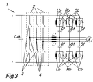
- the capacitors Cb of the parallel resonant circuits according to the invention can either combined into a common star point as shown in FIG. 1 or there are two parallel resonant circuits per phase module provided that leads back to the positive or negative connection of the DC link be ( Figure 3).
- the common star point can also be grounded, in particular a grounding capacitor can be used for this purpose Ce are provided.
- the common star point can also either can be connected to the positive or negative connection of the DC link.
- the invention thus provides a converter circuit arrangement with a filter on the load side, in which the total losses are available seen can be reduced.
Landscapes
- Engineering & Computer Science (AREA)
- Power Engineering (AREA)
- Life Sciences & Earth Sciences (AREA)
- Sustainable Development (AREA)
- Sustainable Energy (AREA)
- Transportation (AREA)
- Mechanical Engineering (AREA)
- Power Conversion In General (AREA)
- Inverter Devices (AREA)
Abstract
Description
- Fig. 1
- Ein erstes Ausführungsbeispiel des erfindungsgemässen Schaltungsaufbaus;
- Fig. 2
- Ein zweites Ausführungsbeispiel des erfindungsgemässen Schaltungsaufbaus;
- Fig. 3
- Ein drittes Ausführungsbeispiel des erfindungsgemässen Schaltungsaufbaus.
- 1
- Stromrichterschaltungsanordnung
- 2
- Phasenbaustein
- 3
- Leistungshalbleiterschalter
- 4
- Lastanschluss
- 5
- Last
- Lf
- Filterinduktivität
- Cf
- Filterkondensator
- Lb
- Dämpfungsinduktivität
- Cb
- Dämpfungskondensator
- Rb
- Dämpfungswiderstand
- Ce
- Erdungskondensator
- Czk
- Zwrischenkreiskondensator
- +
- Plusanschluss
- -
- Minusanschluss
Claims (9)
- Stromrichterschaltungsanordnung (1) mit mindestens einem an einen Zwischenkreis (Czk) angeschlossenen Phasenbaustein (2), der eine Serieschaltung von Leistungshalbleiterschaltern (3) umfasst, wobei ein mittlerer Knotenpunkt der Serieschaltung einen Lastanschluss (4) bildet, und mit einem Filternetzwerk (Cf, Lf), das zwischen den Lastanschluss (4) und eine Last (5) geschaltet ist und eine Hauptresonanzfrequenz bildet, dadurch gekennzeichnet, dass das Filternetzwerk (Cf, Lf) Dämpfungsmittel (Cb, Lb, Rb) umfasst, die für eine selektive Dämpfung der Hauptresonanzfrequenz ausgebildet sind.
- Stromrichterschaltungsanordnung nach Anspruch 1, dadurch gekennzeichnet, dass das Filternetzwerk pro Phasenbaustein (2) einen Tiefpass mit einer Serieschaltung einer Filterinduktivität (Lf) und einem Filterkondensator (Cf) umfasst, wobei die Last (5) an den gemeinsamen Knotenpunkt der Serieschaltung der Filterinduktivität (Lf) und des Filterkondensators (Cf) angeschlossen ist.
- Stromrichterschaltungsanordnung nach Anspruch 2, dadurch gekennzeichnet, dass die Dämpfungsmittel pro Phasenbaustein (2) mindestens einen mit dem Filterkondensator (Cf) in Serie geschalteten Parallelschwingkreis mit einer Dämpfungsinduktivität (Lb), einem Dämpfungskondensator (Cb) und einem Dämpfungswiderstand (Rb) umfassen.
- Stromrichterschaltungsanordnung nach Anspruch 3, dadurch gekennzeichnet, dass die Parallelschwingkreise aller Phasenbausteine (2) auf einen gemeinsamen Sternpunkt geführt sind.
- Stromrichterschaltungsanordnung nach Anspruch 4, dadurch gekennzeichnet, dass der gemeinsame Sternpunkt der Parallelschwingkreise geerdet ist.
- Stromrichterschaltungsanordnung nach Anspruch 4, dadurch gekennzeichnet, dass der gemeinsame Sternpunkt der Parallelschwingkreise über einen Erdungskondensator (Ce) geerdet ist.
- Stromrichterschaltungsanordnung nach Anspruch 4, dadurch gekennzeichnet, dass der gemeinsame Sternpunkt des Parallelschwingkreise entweder mit dem Plusanschluss (+) oder dem Minusanschluss (-) verbunden ist.
- Stromrichterschaltungsanordnung nach Anspruch 3, dadurch gekennzeichnet, dass pro Phasenbaustein (2) zwei Filterkondensatoren (Cf) und zwei Parallelschwingkreise vorgesehen sind, von denen der eine ausserdem mit dem Minusanschluss (-) des Zwischenkreises (Czk) und der andere ausserdem mit dem Plusanschluss (+) des Zwischenkreises (Czk) verbunden ist.
- Stromrichterschaltungsanordnung nach einem der Ansprüche 3 bis 8, dadurch gekennzeichnet, dass der Parallelschwingkreis eine Resonanzfrequenz aufweist, die um weniger als einen Faktor 2 von der Hauptresonanzfrequenz abweicht und insbesondere ungefähr gleich der Hauptresonanzfrequenz ist.
Applications Claiming Priority (2)
| Application Number | Priority Date | Filing Date | Title |
|---|---|---|---|
| DE19637290A DE19637290A1 (de) | 1996-09-13 | 1996-09-13 | Stromrichterschaltungsanordnung mit lastseitigem Filter |
| DE19637290 | 1996-09-13 |
Publications (3)
| Publication Number | Publication Date |
|---|---|
| EP0829948A2 true EP0829948A2 (de) | 1998-03-18 |
| EP0829948A3 EP0829948A3 (de) | 1999-05-19 |
| EP0829948B1 EP0829948B1 (de) | 2004-03-03 |
Family
ID=7805510
Family Applications (1)
| Application Number | Title | Priority Date | Filing Date |
|---|---|---|---|
| EP97810592A Expired - Lifetime EP0829948B1 (de) | 1996-09-13 | 1997-08-21 | Stromrichterschaltungsanordnung mit lastseitigem Filter |
Country Status (2)
| Country | Link |
|---|---|
| EP (1) | EP0829948B1 (de) |
| DE (2) | DE19637290A1 (de) |
Cited By (8)
| Publication number | Priority date | Publication date | Assignee | Title |
|---|---|---|---|---|
| EP0948121A3 (de) * | 1998-03-30 | 2000-03-15 | Asea Brown Boveri AG | Lastseitige Filteranordnung für eine Stromrichter-Schaltungsanordnung |
| EP1318594A1 (de) * | 2001-12-10 | 2003-06-11 | ABB Schweiz AG | Stromrichterschaltungsanordnung zur Erhöhung einer Wechselspannung |
| AT410999B (de) * | 2000-12-05 | 2003-09-25 | Elin Ebg Traction Gmbh | Stromrichtergespeiste antriebseinheit |
| EP1411621A1 (de) * | 2002-10-16 | 2004-04-21 | Schaffner Emv Ag | Anpass-Schaltung zur Begrenzung der Reflexionen in Verbindungskabeln zu Drehfeldmaschinen |
| EP1126573A3 (de) * | 2000-02-15 | 2005-08-31 | Siemens Aktiengesellschaft | Bedämpfungseinrichtung für wenigstens ein elektrisches Kabel |
| DE102006042384A1 (de) * | 2006-09-08 | 2008-03-27 | Siemens Ag | Umrichter und Verfahren zur Steuerung eines Umrichters |
| US8994232B2 (en) | 2009-07-17 | 2015-03-31 | Siemens Aktiengesellschaft | Star-point reactor |
| CN110190790A (zh) * | 2018-02-19 | 2019-08-30 | 株式会社捷太格特 | 马达控制装置 |
Families Citing this family (6)
| Publication number | Priority date | Publication date | Assignee | Title |
|---|---|---|---|---|
| DE19908124C2 (de) * | 1999-02-25 | 2003-04-30 | Aloys Wobben | Wechselrichter ohne Oberschwingungen |
| DE19918093A1 (de) * | 1999-04-21 | 2000-11-02 | Epcos Ag | Filtermodul |
| DE19952886A1 (de) * | 1999-11-03 | 2001-05-10 | Abb Research Ltd | Mehrfachstromrichter |
| DE102012005622B4 (de) | 2012-03-22 | 2022-03-10 | Sew-Eurodrive Gmbh & Co Kg | Schaltungsanordnung |
| CN106335376A (zh) * | 2016-11-03 | 2017-01-18 | 北京全路通信信号研究设计院集团有限公司 | 一种牵引回流装置 |
| DE102018010146A1 (de) * | 2018-12-24 | 2020-06-25 | Finepower Gmbh | Vorrichtung zur Filterung von hochfrequenten Störspannungen in einer Schaltung zur Leistungsfaktorkorrektur |
Family Cites Families (7)
| Publication number | Priority date | Publication date | Assignee | Title |
|---|---|---|---|---|
| GB1450931A (en) * | 1973-01-17 | 1976-09-29 | Ass Elect Ind | Frequency selective damping circuits for use in ac power systems |
| ATE73967T1 (de) * | 1987-12-04 | 1992-04-15 | Siemens Ag | Hochpass einer filteranordnung fuer eine mit stromrichtern verbundene leitung. |
| US4967334A (en) * | 1989-09-12 | 1990-10-30 | Sundstrand Corporation | Inverter input/output filter system |
| JPH06292365A (ja) * | 1992-10-30 | 1994-10-18 | Fuji Electric Co Ltd | Pwmインバータの制御方法および制御装置 |
| US5343381A (en) * | 1993-02-25 | 1994-08-30 | Hydro-Quebec | Electrical dampening circuit for dampening resonance of a power signal in a power distribution network |
| CH693524A5 (de) * | 1994-05-11 | 2003-09-15 | Schaffner Emv Ag | Einrichtung zur Begrenzung der Aenderungsgeschwindigkeit der Ausgangsgrössen eines über einen Gleichspannungszwischenkreis selbstgeführten mehrphasigen Umrichters. |
| CH693523A5 (de) * | 1994-05-11 | 2003-09-15 | Schaffner Emv Ag | Einrichtung zur Begrenzung der Aenderungsgeschwindigkeit der ausgangsseitigen Spannung eines selbstgeführten mehrphasigen Umrichters. |
-
1996
- 1996-09-13 DE DE19637290A patent/DE19637290A1/de not_active Withdrawn
-
1997
- 1997-08-21 DE DE59711361T patent/DE59711361D1/de not_active Expired - Lifetime
- 1997-08-21 EP EP97810592A patent/EP0829948B1/de not_active Expired - Lifetime
Cited By (13)
| Publication number | Priority date | Publication date | Assignee | Title |
|---|---|---|---|---|
| EP0948121A3 (de) * | 1998-03-30 | 2000-03-15 | Asea Brown Boveri AG | Lastseitige Filteranordnung für eine Stromrichter-Schaltungsanordnung |
| EP1126573A3 (de) * | 2000-02-15 | 2005-08-31 | Siemens Aktiengesellschaft | Bedämpfungseinrichtung für wenigstens ein elektrisches Kabel |
| AT410999B (de) * | 2000-12-05 | 2003-09-25 | Elin Ebg Traction Gmbh | Stromrichtergespeiste antriebseinheit |
| EP1318594A1 (de) * | 2001-12-10 | 2003-06-11 | ABB Schweiz AG | Stromrichterschaltungsanordnung zur Erhöhung einer Wechselspannung |
| EP1411621A1 (de) * | 2002-10-16 | 2004-04-21 | Schaffner Emv Ag | Anpass-Schaltung zur Begrenzung der Reflexionen in Verbindungskabeln zu Drehfeldmaschinen |
| DE102006042384B4 (de) * | 2006-09-08 | 2008-09-11 | Siemens Ag | Umrichter und Verfahren zur Steuerung eines Umrichters |
| DE102006042384A1 (de) * | 2006-09-08 | 2008-03-27 | Siemens Ag | Umrichter und Verfahren zur Steuerung eines Umrichters |
| US7948779B2 (en) | 2006-09-08 | 2011-05-24 | Siemens Aktiengesellschaft | Converter with reduced harmonic waves |
| US8994232B2 (en) | 2009-07-17 | 2015-03-31 | Siemens Aktiengesellschaft | Star-point reactor |
| CN110190790A (zh) * | 2018-02-19 | 2019-08-30 | 株式会社捷太格特 | 马达控制装置 |
| EP3528381A3 (de) * | 2018-02-19 | 2019-11-20 | Jtekt Corporation | Motorsteuergerät |
| US10673360B2 (en) | 2018-02-19 | 2020-06-02 | Jtekt Corporation | Motor controller |
| CN110190790B (zh) * | 2018-02-19 | 2024-03-12 | 株式会社捷太格特 | 马达控制装置 |
Also Published As
| Publication number | Publication date |
|---|---|
| DE19637290A1 (de) | 1998-03-19 |
| EP0829948A3 (de) | 1999-05-19 |
| DE59711361D1 (de) | 2004-04-08 |
| EP0829948B1 (de) | 2004-03-03 |
Similar Documents
| Publication | Publication Date | Title |
|---|---|---|
| EP0829948B1 (de) | Stromrichterschaltungsanordnung mit lastseitigem Filter | |
| DE60025865T2 (de) | Halbleitervorrichtung und elektrische Stromwandlungsvorrichtung | |
| EP3075056B1 (de) | Verfahren zum betreiben eines wechselrichters und wechselrichter mit einem schalter zwischen einem mittelpunkt eines gleichspannungszwischenkreises und einem anschluss für einen nullleiter eines wechselstromnetzes | |
| DE10042624B4 (de) | Dreipegel-Wechselrichter-Vorrichtung | |
| EP0899859A2 (de) | U-Umrichter | |
| WO2002049196A2 (de) | Umrichter mit integrierten zwischnkreiskondensatoren | |
| EP0660496A2 (de) | Umrichteranordnung mit niederinduktivem Kommutierungskreis | |
| EP0399139A2 (de) | Verfahren zur Erweiterung eines dreistufigen regelmässigen Koppelfeldes | |
| EP0682402A1 (de) | Einrichtung zur Begrenzung der Änderungsgeschwindigkeit der Ausgangsgrössen eines über einen Gleichspannungszwischenkreis selbstgeführten Umrichters | |
| DE3410580C2 (de) | ||
| DE69516879T2 (de) | Zu einer gedruckten schaltplatte gehörende koppelvorrichtung, die eine kapazität anzeigt und/oder steuert | |
| EP0948121B1 (de) | Lastseitige Filteranordnung für eine Stromrichter-Schaltungsanordnung | |
| DE102018216916A1 (de) | Einrichtung zur kontaktlosen induktiven Energieübertragung, insbesondere für induktive Ladevorgänge bei Kraftfahrzeugen | |
| DE19650820A1 (de) | Stromversorgungs-Störsignalbeseitigungs- verfahren und Halbleitervorrichtung | |
| EP0678977B1 (de) | Mit akustischen Oberflächenwellen arbeitendes Filter | |
| DE10310577A1 (de) | Nullspannungsfilter für Umrichter mit selbstgeführtem Netzstromrichter (AFE) und Gleichspannungszwischenkreis | |
| DE19741430A1 (de) | Schaltungsanordnung und Verfahren zur Unterdrückung störender Rückwirkungen eines Umrichters | |
| DE102019205946A1 (de) | Filterschaltung zum Reduzieren von Rückwirkungen eines Verbrauchers auf eine Energieversorgung | |
| EP1318594B1 (de) | Stromrichterschaltungsanordnung zur Erhöhung einer Wechselspannung | |
| DE102005030658A1 (de) | Halbleitervorrichtung mit einer verbesserten spannungsgesteuerten Oszillatorschaltung | |
| DE102005031372A1 (de) | Wechselrichter mit Sinusfilter | |
| DE3513032C2 (de) | Netzgerät | |
| EP3477835A1 (de) | Umrichter mit gleichtaktfilter | |
| DE19647933A1 (de) | Leistungselektronische Schaltungsanordnung | |
| DE4303317A1 (de) | Umrichterbrücke |
Legal Events
| Date | Code | Title | Description |
|---|---|---|---|
| PUAI | Public reference made under article 153(3) epc to a published international application that has entered the european phase |
Free format text: ORIGINAL CODE: 0009012 |
|
| AK | Designated contracting states |
Kind code of ref document: A2 Designated state(s): DE FR GB IT |
|
| TPAD | Observations filed by third parties |
Free format text: ORIGINAL CODE: EPIDOS TIPA |
|
| PUAL | Search report despatched |
Free format text: ORIGINAL CODE: 0009013 |
|
| AK | Designated contracting states |
Kind code of ref document: A3 Designated state(s): AT BE CH DE DK ES FI FR GB GR IE IT LI LU MC NL PT SE |
|
| 17P | Request for examination filed |
Effective date: 19991015 |
|
| AKX | Designation fees paid |
Free format text: DE FR GB IT |
|
| RAP1 | Party data changed (applicant data changed or rights of an application transferred) |
Owner name: ABB INDUSTRIE AG |
|
| RAP1 | Party data changed (applicant data changed or rights of an application transferred) |
Owner name: ABB SCHWEIZ AG |
|
| GRAP | Despatch of communication of intention to grant a patent |
Free format text: ORIGINAL CODE: EPIDOSNIGR1 |
|
| GRAS | Grant fee paid |
Free format text: ORIGINAL CODE: EPIDOSNIGR3 |
|
| GRAA | (expected) grant |
Free format text: ORIGINAL CODE: 0009210 |
|
| AK | Designated contracting states |
Kind code of ref document: B1 Designated state(s): DE FR GB IT |
|
| PG25 | Lapsed in a contracting state [announced via postgrant information from national office to epo] |
Ref country code: GB Free format text: LAPSE BECAUSE OF FAILURE TO SUBMIT A TRANSLATION OF THE DESCRIPTION OR TO PAY THE FEE WITHIN THE PRESCRIBED TIME-LIMIT Effective date: 20040303 |
|
| REG | Reference to a national code |
Ref country code: GB Ref legal event code: FG4D Free format text: NOT ENGLISH |
|
| REF | Corresponds to: |
Ref document number: 59711361 Country of ref document: DE Date of ref document: 20040408 Kind code of ref document: P |
|
| GBV | Gb: ep patent (uk) treated as always having been void in accordance with gb section 77(7)/1977 [no translation filed] |
Effective date: 20040303 |
|
| ET | Fr: translation filed | ||
| PLBE | No opposition filed within time limit |
Free format text: ORIGINAL CODE: 0009261 |
|
| STAA | Information on the status of an ep patent application or granted ep patent |
Free format text: STATUS: NO OPPOSITION FILED WITHIN TIME LIMIT |
|
| 26N | No opposition filed |
Effective date: 20041206 |
|
| PGFP | Annual fee paid to national office [announced via postgrant information from national office to epo] |
Ref country code: DE Payment date: 20140821 Year of fee payment: 18 |
|
| PGFP | Annual fee paid to national office [announced via postgrant information from national office to epo] |
Ref country code: FR Payment date: 20140821 Year of fee payment: 18 |
|
| PGFP | Annual fee paid to national office [announced via postgrant information from national office to epo] |
Ref country code: IT Payment date: 20140828 Year of fee payment: 18 |
|
| REG | Reference to a national code |
Ref country code: DE Ref legal event code: R119 Ref document number: 59711361 Country of ref document: DE |
|
| PG25 | Lapsed in a contracting state [announced via postgrant information from national office to epo] |
Ref country code: IT Free format text: LAPSE BECAUSE OF NON-PAYMENT OF DUE FEES Effective date: 20150821 |
|
| REG | Reference to a national code |
Ref country code: FR Ref legal event code: ST Effective date: 20160429 |
|
| PG25 | Lapsed in a contracting state [announced via postgrant information from national office to epo] |
Ref country code: DE Free format text: LAPSE BECAUSE OF NON-PAYMENT OF DUE FEES Effective date: 20160301 |
|
| PG25 | Lapsed in a contracting state [announced via postgrant information from national office to epo] |
Ref country code: FR Free format text: LAPSE BECAUSE OF NON-PAYMENT OF DUE FEES Effective date: 20150831 |