EP0829668A1 - Vanne électromagnétique - Google Patents
Vanne électromagnétique Download PDFInfo
- Publication number
- EP0829668A1 EP0829668A1 EP19970112113 EP97112113A EP0829668A1 EP 0829668 A1 EP0829668 A1 EP 0829668A1 EP 19970112113 EP19970112113 EP 19970112113 EP 97112113 A EP97112113 A EP 97112113A EP 0829668 A1 EP0829668 A1 EP 0829668A1
- Authority
- EP
- European Patent Office
- Prior art keywords
- solenoid valve
- valve member
- valve according
- support member
- channel
- Prior art date
- Legal status (The legal status is an assumption and is not a legal conclusion. Google has not performed a legal analysis and makes no representation as to the accuracy of the status listed.)
- Granted
Links
Images

Classifications
-
- F—MECHANICAL ENGINEERING; LIGHTING; HEATING; WEAPONS; BLASTING
- F16—ENGINEERING ELEMENTS AND UNITS; GENERAL MEASURES FOR PRODUCING AND MAINTAINING EFFECTIVE FUNCTIONING OF MACHINES OR INSTALLATIONS; THERMAL INSULATION IN GENERAL
- F16K—VALVES; TAPS; COCKS; ACTUATING-FLOATS; DEVICES FOR VENTING OR AERATING
- F16K31/00—Actuating devices; Operating means; Releasing devices
- F16K31/02—Actuating devices; Operating means; Releasing devices electric; magnetic
- F16K31/06—Actuating devices; Operating means; Releasing devices electric; magnetic using a magnet, e.g. diaphragm valves, cutting off by means of a liquid
- F16K31/0686—Braking, pressure equilibration, shock absorbing
- F16K31/0693—Pressure equilibration of the armature
-
- F—MECHANICAL ENGINEERING; LIGHTING; HEATING; WEAPONS; BLASTING
- F16—ENGINEERING ELEMENTS AND UNITS; GENERAL MEASURES FOR PRODUCING AND MAINTAINING EFFECTIVE FUNCTIONING OF MACHINES OR INSTALLATIONS; THERMAL INSULATION IN GENERAL
- F16K—VALVES; TAPS; COCKS; ACTUATING-FLOATS; DEVICES FOR VENTING OR AERATING
- F16K39/00—Devices for relieving the pressure on the sealing faces
- F16K39/02—Devices for relieving the pressure on the sealing faces for lift valves
- F16K39/022—Devices for relieving the pressure on the sealing faces for lift valves using balancing surfaces
-
- Y—GENERAL TAGGING OF NEW TECHNOLOGICAL DEVELOPMENTS; GENERAL TAGGING OF CROSS-SECTIONAL TECHNOLOGIES SPANNING OVER SEVERAL SECTIONS OF THE IPC; TECHNICAL SUBJECTS COVERED BY FORMER USPC CROSS-REFERENCE ART COLLECTIONS [XRACs] AND DIGESTS
- Y10—TECHNICAL SUBJECTS COVERED BY FORMER USPC
- Y10T—TECHNICAL SUBJECTS COVERED BY FORMER US CLASSIFICATION
- Y10T137/00—Fluid handling
- Y10T137/7722—Line condition change responsive valves
- Y10T137/7837—Direct response valves [i.e., check valve type]
- Y10T137/7904—Reciprocating valves
- Y10T137/7905—Plural biasing means
Definitions
- the invention relates to a solenoid valve, with an inlet duct that can be connected to a pressure medium source and an outlet duct that can be connected with a consumer, and with an overflow opening arranged between the two ducts the valve seat enclosing the overflow opening rests and is acted upon in the closing direction.
- a solenoid valve of this type in the form of a 2/3-way valve is apparent from DE-AS 1 o31 o73. It has a base body with an inlet channel acted upon by the feed pressure and an outlet channel leading to a consumer.
- An electromagnet is arranged on the base body and has a valve member which is biased by a return spring device into a closed position in which it bears against a valve seat defining an overflow opening between the inlet channel and the outlet channel.
- the valve member is switched to an open position by excitation of the electromagnet, in which it is lifted off the valve seat and the overflow opening is opened.
- a movable support member acted upon by a control pressure is present, which acts on the valve member through the working channel in the opening direction.
- the opening movement of the valve member is supported by fluid force.
- the valve member is acted upon by the support member acted upon by a control pressure in the opening direction, so that it experiences an actuating force effective in the opening direction, which counteracts the closing force caused by the feed pressure.
- the resulting fluid force biasing the valve member into the closed position can thereby be reduced as required, so that the driving force to be used by the electromagnet for the opening movement is only low. Even if the cross-section of the overflow opening is very large and the valve member is accordingly biased into the closed position with a high closing force caused by the supply pressure, the oppositely acting support member can at least partially compensate for the fluid-related forces, which results in short switching times or low energy consumption allows rapid movements of the valve member.
- a corresponding one large overflow opening enables high flow values, and this with a relatively small electromagnet.
- control pressure can be variably adjusted.
- the resulting pressure forces acting on the valve member can be specifically influenced and predetermined in accordance with the respective application.
- control pressure corresponds to the feed pressure.
- control fluid supplying the control pressure can be branched off from the inlet channel, so that a separate fluid supply is not necessary.
- the support member expediently has a movable drive section in one pass is movably received under seal, which connects the outlet channel with a control chamber acted upon by the control pressure.
- the drive section can form a movable section of the wall delimiting the outlet channel and is acted upon on the one hand by the control pressure and on the other hand by the outlet pressure prevailing in the outlet channel.
- the drive section is expediently formed by a displaceable piston, on which an actuating plunger which projects to the valve member is expediently arranged and which has a considerably smaller cross section than the outlet duct, so that it reduces the flow cross section of the outlet duct only slightly.
- the support member preferably acts through the overflow opening on the end region of the valve member covering the overflow opening in the closed position.
- the closing force caused by the supply pressure is already greatly reduced, and even a weak electromagnet is able to move the valve member fully to the open position.
- the advantage of this arrangement is that the support member does not have to be pushed back immediately in the subsequent closing movement. Rather, this is only acted upon by the valve member when the valve member already has a certain kinetic energy, so that the valve member can safely switch to the closed position while simultaneously pushing back the support member.
- the closing process can be accelerated by providing an acceleration spring device which drives the valve member at the beginning of the closing movement, but only during the last section the opening movement of the valve member is tensioned. It therefore only acts during the initial movement phase of the opening movement in order to give the valve member a strong acceleration pulse.
- the solenoid valves 1 shown in the drawing each have a base body 2, on which an electromagnet 3 is in particular detachably fixed.
- the electromagnet 3, which is only indicated schematically, has at least one coil 4, which is connected to connection means 5, via which are used for the operation of the electromagnet 3 required electrical energy is supplied.
- a fixed armature 6 Arranged within the coil 4 is a fixed armature 6, in the axial extension of which a longitudinally movable armature 7 is arranged on the side facing the base body 2.
- the movable armature 7 dips with a partial length into an armature receptacle 8 which adjoins the fixed armature 6 and is enclosed by the coil 4.
- An inlet channel 12 and an outlet channel 13 are formed in the base body 2. Each of these channels 12, 13 opens out with a connection opening 14 on the outside of the base body 2.
- the inlet channel 12 can be connected via the associated connection opening 14 to a pressure medium source P, which supplies pressurized fluidic pressure medium, in particular compressed air.
- the outlet duct 13 can be connected via its connection opening 14 to a consumer V to be actuated by fluid force, for example a working cylinder.
- the inlet channel 12 and the outlet channel 13 are connected in the interior of the base body 2 via a closable overflow opening 15. This is surrounded on the side facing the inlet channel 12 by an annular, self-contained valve seat 19, which is preferably part of the base body 2.
- the overflow opening 15 opens into an inflow chamber 16, which is formed by an expansion of the inlet channel 12.
- a valve member 17 protrudes into this inflow chamber 16, which is formed, for example, by the movable armature 7.
- the inflow chamber 16 is open to a mounting surface 18 located on the outside of the base body 2, the electromagnet 3 being attached to this mounting surface 18, so that the end section 22 of the movable armature 7 or the valve member 17 protruding from the armature receptacle 8 protrudes into the inflow chamber 16.
- the electromagnet 3 also forms a sealing cover for the inflow chamber 16.
- the inflow chamber 16 preferably has a circular cross section, the overflow opening 15 being formed, in particular, centrally in the bottom 23 of the inflow chamber 16 opposite the electromagnet. This also has the valve seat 19.
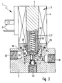
- the valve member 17 can be switched in a linear direction of movement indicated by the double arrow 24 between a closed position shown in FIG. 1 and an open position shown in FIG. 2.
- the switching movement of the valve member 17 is preferably a linear stroke movement, the valve member 17 expediently has a substantially cylindrical shape and the direction of movement 24 coincides with its longitudinal axis.
- the valve member 17 is opposite the overflow opening 15 and the valve seat 19 on the side of the inlet channel 12. In the closed position, the valve member 17 sits tightly on the valve seat 19 with a closure part 25 provided on the end face of the projecting end section 22.
- the exemplary solenoid valve 1 is thus a seat valve.
- the closure part 25 is preferably an element consisting of sealing material, in particular of rubber-elastic material, which is fixed on the valve member 17.
- a return spring device 26 constantly biases the valve member 17 in the closing direction 27. It is supported, for example, between a projection 28 of the valve member 17 and a housing part 29 of the electromagnet 3. It encloses the valve member 17 coaxially. In the closed position, there is an intermediate space 33 between the rear end section 32 of the valve member 17 and the fixed armature 6.
- the overflow opening 15 is closed, so that no pressure medium from the inlet channel 12 in can flow over the outlet channel 13.
- valve member 17 By energizing the coil 4 of the electromagnet 3, the valve member 17 can be switched to the open position shown in FIG. 2.
- the valve member 17 is attracted to the magnetic field and shifted in the opening direction 34 until it comes to rest on the fixed armature 6.
- the gap 33 is closed in the open position.
- the width of the intermediate space 33 measured in the direction of movement 24 thus defines the switching path s of the valve member 17 between the closed position and the open position.
- the return spring device 26 When the valve member 17 is moved into the open position, the return spring device 26 is compressed. It contributes to the fact that when the coil 4 is de-energized, the valve member 17 is returned to the closed position that represents the starting position according to FIG. 1.
- the overflow opening 15 is first connected to a first channel section 35 of the outlet channel 13, which extends coaxially with the overflow opening 15 and the valve member 17. It therefore extends in the direction of movement 24 of the valve member 17.
- This second channel section 35 is followed by a second channel section 36 of the outlet channel 13, which extends sideways, so that the course of the outlet channel 13 has a kink. 1 and 2, the second channel section extends at right angles to the first channel section 35, so that the pressure medium flowing out through the outlet channel 13 undergoes a relatively sharp deflection.
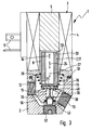
- a more aerodynamic course of the outlet channel 13 is provided, in that the second channel section 36 slopes obliquely at an obtuse angle with respect to the first channel section 35.
- FIG. 3 shows an embodiment of the solenoid valve, in which the valve member 17 is comparable to FIG. 1 in the closed position.
- valve member 17 In the closed position, the valve member 17 is acted upon in the closing direction 27 by the feed pressure on the inlet side, that is to say by the pressure prevailing in the inlet channel 12.
- the resulting closing force which is effective in the closing direction 27
- only one effective surface section 37 pointing in the opening direction 34 is relevant, the area of which corresponds to the cross-sectional area of the overflow opening 15 corresponds.
- the valve member 17 is pressure balanced. The resulting closing force results from the pressure difference in relation to the surfaces mentioned.
- a high magnetic force is therefore required to switch the valve member 17 into the open position.
- a movable support member 38 acted upon by a control pressure p S is provided in the described solenoid valve 1, which can act on the valve member 17 through the outlet channel 13 in the opening direction 34.
- the support member 38 thus exerts a force acting in the opening direction 34 on the valve member 17 and thereby supports the activity of the electromagnet.
- the support force of the support member 38 counteracts the closing force of the feed pressure, so that the resulting closing force due to the pressure medium can be minimized and the electromagnet only requires a small amount of power in order to switch the valve member 17 very quickly into the open position. There is therefore a quick-switching valve which, even with large flow cross-sections and the associated high flow values, enables extremely short switching times with low actuation energy.
- the arrangement is such that an extension 42 is provided in the extension of the first channel section 35 of the outlet channel 13, which connects the outlet channel 13 to a control chamber 43 which can be acted upon by the control pressure p s .
- the support member 38 has a drive section 44, for example a diaphragm or, as shown, a piston, which is arranged in the passage 42 so as to be displaceable under sealing in an adjustment direction 45 indicated by a double arrow.
- the drive section 44 is thus acted upon from the side of the outlet channel 13 by the pressure prevailing therein and in the opposite direction by the control pressure p s prevailing in the control chamber 43. Since the control pressure p s, at least in the closed position of the valve member 17, is considerably greater than the pressure in the outlet channel 13, a support force 46 results with which the support member 38 is pressed in the direction of the valve member 13.
- the support member 38 On the side of the drive section 44 facing the outlet channel 13, the support member 38 has an actuating plunger 47 which projects in the longitudinal direction of the first channel section 35 to the overflow opening 15 and, in the exemplary embodiment according to FIG. 1, with its free end 48 on the section 49 covering the overflow opening 15 of Valve member 17 abuts. 1 and 2, a loose contact is preferably provided here, that is to say a purely touching contact.
- a fixed connection is provided between the support member 38 and the valve member 17, in that the actuating plunger 47 is expediently fixed in any manner with its free end 48 to the covering part 49.
- the support member 38 could even be an integral part of the valve member 17.
- control pressure p s prevailing in the control chamber 43 corresponds to the feed pressure on the inlet side.
- control surface 53 which is acted upon by the control pressure p s and faces the control chamber 43, corresponds at least approximately to the cross-sectional area of the overflow opening 17, this has the consequence that the closing force exerted on the valve member 17 by the supply pressure is practically completely canceled.
- the drive energy required to actuate the solenoid valve only has to be oriented essentially to the actuating force of the return spring device 26, which, however, can be designed to be relatively weak.
- the vibration resistance of the solenoid valve is usually sufficient to ensure.
- control pressure p s is supplied to the control chamber 43 separately.
- the control chamber 43 therefore has a connection opening 54 through which a connection to a further pressure medium source 55 which supplies the control pressure p s can be established.
- This preferably also enables a variable setting of the control pressure p s in order to influence the support force and to be able to variably specify the desired resulting closing force of the valve member 17 as required.
- control chamber 43 can also be connected to the pressure medium source P supplying the feed pressure in order to reduce the structural outlay.
- a corresponding embodiment is shown in FIG. 3, where the control fluid supplying the control pressure is branched off from the inlet channel 12.
- a control channel 56 is formed in the interior of the base body 2, which connects the inlet channel 12 to the control chamber 43.
- a sealing plug which closes the control chamber 43 tightly and enables the mounting of the support member 38 and a sealing device 58 which serves to seal between the base body 2 and the support member 38.
- the latter is ring-shaped and can be mounted in the embodiment shown in FIGS. 1 and 2 via the connection opening 54.
- an external pressure medium line 59 can also be provided in order to connect the control chamber 43 to the common pressure medium source P.
- a pressure setting device 62 which is only indicated in FIG. 1 and which allows the control pressure p s to be specified as required, can be switched on both in the pressure medium line 59 and in the control channel 56.
- the control pressure p s is preferably constantly present in the control chamber 43.
- the support force 46 is available without delay when the solenoid valve 1 is opened.
- the valve member 17 is moving in the opening direction 34 during the opening process, it is additionally pushed by the support member 38.
- the support member 38 dips a little way into the inflow chamber 16 through the overflow opening 15.
- the arrangement is such that the outlet duct 13 is not blocked by the support member 38, in particular by the drive section 44 being designed such that it is open when the valve member 17th does not protrude, or only insignificantly, from the passage 42 into the outlet duct 13.
- the actuating plunger 47 which is arranged centrally, for example, is made very thin in relation to the flow cross section of the outlet channel 13.
- the support member 38 In the closed position of the valve member 17, the support member 38 assumes the basic position shown in FIGS. 1 and 3. In the exemplary embodiment according to FIGS. 1 and 2, measures have been taken on the basis of which the maximum adjustment path a of the support element 38, measured from the basic position, is less than the switching path s of the valve element 17. This has the consequence that the support element 38 only at the beginning of the Opening movement of the valve member 17 acts on it. The remaining stroke until the open position is reached is carried out by the valve member 17 alone and without being acted upon by the support member 38. As a result, in the open position of the valve member 17, an intermediate space 63 remains between the latter and the associated free end 48 of the support member 38.
- the decoupling thus present in the open position between the valve member and the support member 38 has the result that, during the subsequent closing movement, the valve member 17 is initially unaffected by the support member 38 is movable in the closing direction 27. Only when the gap 63 is closed after a short distance, does the valve member 17 act on the support member 38 and press it back against the control pressure p s into the basic position. The pushing back is facilitated in that the valve member receives kinetic energy until it hits the support member 38, so that the support member 38 is returned to the basic position with momentum.
- the adjustment distance of the support member 38 is achieved by providing at least one stop 64 in the adjustment path of the support member 38 and in particular the drive part 44.
- This stop 64 projects, for example, into the passage 42 and / or into the first channel section 35. Since a subdivision between the valve member 17 and the support member 38 is not provided in the embodiment of FIG. 3, the two parts are always connected until the open position is reached. Switching to the closed position therefore requires a somewhat higher force than in the embodiment according to FIGS. 1 and 2. A stop is not provided here.
- Acceleration spring device 65 which drives valve member 17 at the beginning of the closing movement and is tensioned only during the last section of the opening movement of valve member 17. Such is realized in the embodiment of FIGS. 1 and 2.
- the valve member 17 has a receptacle 66 which is open to the end face of the rear end section 32.
- the acceleration spring device 65 is formed, for example formed by a helical compression spring, which acts on a support member 67, so that this protrudes with a support section 68 beyond the end face of the valve member 17.
- a stop 69 defines this position of the support member 67.
- the acceleration spring device 65 expands abruptly, the valve member 17 being repelled by the fixed armature 6 in the closing direction.
- the thus obtained Kinetic energy also aids in pushing the support member 38 back to the home position.
- the exemplary solenoid valve 1 is a 2/2-way valve. However, it would be conceivable to apply the principle according to the invention to other valve types.
Landscapes
- Engineering & Computer Science (AREA)
- General Engineering & Computer Science (AREA)
- Mechanical Engineering (AREA)
- Magnetically Actuated Valves (AREA)
Applications Claiming Priority (2)
| Application Number | Priority Date | Filing Date | Title |
|---|---|---|---|
| DE1996132379 DE19632379C2 (de) | 1996-08-10 | 1996-08-10 | Magnetventil |
| DE19632379 | 1996-08-10 |
Publications (2)
| Publication Number | Publication Date |
|---|---|
| EP0829668A1 true EP0829668A1 (fr) | 1998-03-18 |
| EP0829668B1 EP0829668B1 (fr) | 2001-02-28 |
Family
ID=7802364
Family Applications (1)
| Application Number | Title | Priority Date | Filing Date |
|---|---|---|---|
| EP19970112113 Expired - Lifetime EP0829668B1 (fr) | 1996-08-10 | 1997-07-16 | Vanne électromagnétique |
Country Status (3)
| Country | Link |
|---|---|
| US (1) | US5823505A (fr) |
| EP (1) | EP0829668B1 (fr) |
| DE (2) | DE19632379C2 (fr) |
Cited By (5)
| Publication number | Priority date | Publication date | Assignee | Title |
|---|---|---|---|---|
| WO2003014607A1 (fr) * | 2001-08-06 | 2003-02-20 | Continental Teves Ag & Co. Ohg | Vanne electromagnetique |
| EP1806526A1 (fr) | 2006-01-07 | 2007-07-11 | FESTO AG & Co | Soupape électromagnétique |
| CN102943896A (zh) * | 2012-11-15 | 2013-02-27 | 李志红 | 一种结构紧凑密封性好可靠性高的电磁阀 |
| CN104534681A (zh) * | 2014-12-24 | 2015-04-22 | 浙江双杰铜业有限公司 | 电热水器系统 |
| CN104534150A (zh) * | 2014-12-24 | 2015-04-22 | 浙江双杰铜业有限公司 | 热水器进水电磁阀 |
Families Citing this family (13)
| Publication number | Priority date | Publication date | Assignee | Title |
|---|---|---|---|---|
| US6237631B1 (en) * | 1999-08-19 | 2001-05-29 | Parker-Hannifin Corporation | Low spill quick disconnect coupling |
| US6776391B1 (en) | 1999-11-16 | 2004-08-17 | Continental Teves Ag & Co. Ohg | Electromagnet valve |
| DE102005014100B4 (de) * | 2004-07-15 | 2014-01-02 | Continental Teves Ag & Co. Ohg | Elektromagnetventil, insbesondere für schlupfgeregelte Kraftfahrzeugbremsanlagen |
| US8397745B2 (en) | 2007-02-12 | 2013-03-19 | Colt Irrigation, LLC | Fluid activated flow control apparatus |
| US9341281B2 (en) | 2007-02-12 | 2016-05-17 | Colt Irrigation Llc | Fluid activated flow control apparatus |
| NL2009504C2 (en) * | 2012-09-24 | 2014-03-25 | Daf Trucks Nv | Suspension system for a driver's compartment of a vehicle. |
| DE102013013940B3 (de) * | 2013-08-21 | 2014-11-27 | Festo Ag & Co. Kg | Magnetventil |
| US10571937B1 (en) | 2014-01-23 | 2020-02-25 | Colt Irrigation, LLC | Valve control apparatus |
| US9599286B2 (en) | 2014-01-23 | 2017-03-21 | Colt Irrigation, LLC | Fluid activated flow control apparatus |
| US10088849B2 (en) | 2014-01-23 | 2018-10-02 | Colt Irrigation, LLC | Fluid activated flow control apparatus |
| KR101926914B1 (ko) * | 2016-07-22 | 2018-12-07 | 현대자동차주식회사 | 연료 전지 시스템용 연료 공급 밸브 |
| DE102021211154B3 (de) | 2021-10-04 | 2022-12-29 | Festo Se & Co. Kg | Aktoreinrichtung |
| DE102022119889A1 (de) | 2022-08-08 | 2024-02-08 | Festo Se & Co. Kg | Ventil |
Citations (7)
| Publication number | Priority date | Publication date | Assignee | Title |
|---|---|---|---|---|
| DE1031073B (de) | 1953-04-04 | 1958-05-29 | Erich Herion | Ventil fuer Schaltungen íÀAuf und ZuíÂmit einer elastischen Ventilverschlussscheibe |
| FR1390295A (fr) * | 1964-01-07 | 1965-02-26 | Procédé de compensation des forces tendant à maintenir ou ouvrir un clapet dues à la pression différentielle appliquée à ce clapet | |
| DE1234469B (de) * | 1959-09-21 | 1967-02-16 | Bendix Corp | Entlastetes Ventil |
| GB1579662A (en) * | 1977-04-29 | 1980-11-19 | Shipowners Cargo Res Assoc | Refrigeration control systems |
| FR2567985A1 (fr) * | 1984-07-17 | 1986-01-24 | Singer Co | Soupape de detente actionnee electriquement et installation de conditionnement d'air pour vehicules, notamment pour automobiles, munie d'une telle soupape |
| DE3500802A1 (de) * | 1985-01-11 | 1986-07-17 | Kraftwerk Union AG, 4330 Mülheim | Steuerventil |
| DE3942026A1 (de) * | 1988-12-29 | 1990-07-05 | Yamatake Honeywell Co Ltd | Druckausgeglichenes stell- oder regelventil |
Family Cites Families (6)
| Publication number | Priority date | Publication date | Assignee | Title |
|---|---|---|---|---|
| GB705216A (en) * | 1951-10-19 | 1954-03-10 | Dunlop Rubber Co | Improvements in fluid pressure relief valves |
| DE1205623B (de) * | 1960-11-12 | 1965-11-25 | Concordia Maschinen Und Elek Z | Magnetanker |
| BE754257Q (fr) * | 1968-10-14 | 1970-12-31 | Mac Valves Inc | Soupape d'inversion, notamment a actionnement electromagnetique |
| JPS571881A (en) * | 1980-06-04 | 1982-01-07 | Aisin Seiki Co Ltd | Proportional flow control valve |
| US4821774A (en) * | 1988-04-04 | 1989-04-18 | Chorkey William J | Solenoid operated valve with balancing means |
| DE4137123A1 (de) * | 1991-11-12 | 1993-05-13 | Teves Gmbh Alfred | Drucksteuerventil |
-
1996
- 1996-08-10 DE DE1996132379 patent/DE19632379C2/de not_active Expired - Fee Related
-
1997
- 1997-07-16 DE DE59703038T patent/DE59703038D1/de not_active Expired - Lifetime
- 1997-07-16 EP EP19970112113 patent/EP0829668B1/fr not_active Expired - Lifetime
- 1997-08-04 US US08/905,639 patent/US5823505A/en not_active Expired - Lifetime
Patent Citations (7)
| Publication number | Priority date | Publication date | Assignee | Title |
|---|---|---|---|---|
| DE1031073B (de) | 1953-04-04 | 1958-05-29 | Erich Herion | Ventil fuer Schaltungen íÀAuf und ZuíÂmit einer elastischen Ventilverschlussscheibe |
| DE1234469B (de) * | 1959-09-21 | 1967-02-16 | Bendix Corp | Entlastetes Ventil |
| FR1390295A (fr) * | 1964-01-07 | 1965-02-26 | Procédé de compensation des forces tendant à maintenir ou ouvrir un clapet dues à la pression différentielle appliquée à ce clapet | |
| GB1579662A (en) * | 1977-04-29 | 1980-11-19 | Shipowners Cargo Res Assoc | Refrigeration control systems |
| FR2567985A1 (fr) * | 1984-07-17 | 1986-01-24 | Singer Co | Soupape de detente actionnee electriquement et installation de conditionnement d'air pour vehicules, notamment pour automobiles, munie d'une telle soupape |
| DE3500802A1 (de) * | 1985-01-11 | 1986-07-17 | Kraftwerk Union AG, 4330 Mülheim | Steuerventil |
| DE3942026A1 (de) * | 1988-12-29 | 1990-07-05 | Yamatake Honeywell Co Ltd | Druckausgeglichenes stell- oder regelventil |
Cited By (5)
| Publication number | Priority date | Publication date | Assignee | Title |
|---|---|---|---|---|
| WO2003014607A1 (fr) * | 2001-08-06 | 2003-02-20 | Continental Teves Ag & Co. Ohg | Vanne electromagnetique |
| EP1806526A1 (fr) | 2006-01-07 | 2007-07-11 | FESTO AG & Co | Soupape électromagnétique |
| CN102943896A (zh) * | 2012-11-15 | 2013-02-27 | 李志红 | 一种结构紧凑密封性好可靠性高的电磁阀 |
| CN104534681A (zh) * | 2014-12-24 | 2015-04-22 | 浙江双杰铜业有限公司 | 电热水器系统 |
| CN104534150A (zh) * | 2014-12-24 | 2015-04-22 | 浙江双杰铜业有限公司 | 热水器进水电磁阀 |
Also Published As
| Publication number | Publication date |
|---|---|
| DE19632379C2 (de) | 1999-10-07 |
| DE19632379A1 (de) | 1998-02-19 |
| DE59703038D1 (de) | 2001-04-05 |
| US5823505A (en) | 1998-10-20 |
| EP0829668B1 (fr) | 2001-02-28 |
Similar Documents
| Publication | Publication Date | Title |
|---|---|---|
| EP0829668B1 (fr) | Vanne électromagnétique | |
| DE3638369C2 (de) | Elektromagnetisch gesteuertes Ventil für ein Kraftstoffeinspritzsystem | |
| WO1997048900A1 (fr) | Dispositif d'injection de carburant pour moteurs a combustion interne | |
| WO2010085991A2 (fr) | Soupape de régulation de pression proportionnelle | |
| DE4416279A1 (de) | Magnetventil | |
| EP2558757B1 (fr) | Régulateur de débit | |
| EP1409873A1 (fr) | Bloc de distribution pour un dispositif de regulation, en particulier une machine hydrostatique | |
| DE102014006510B3 (de) | Ventilanordnung | |
| DE2952237A1 (de) | Drucksteuerventil | |
| EP2193298B1 (fr) | Soupape | |
| DE10010690B4 (de) | Ventil | |
| EP2702460B1 (fr) | Vanne pneumatique et son usage pour un consommateur connecté | |
| WO2017080602A1 (fr) | Soupape pour commander l'écoulement d'un fluide | |
| EP0483585B1 (fr) | Valve d'étranglement proportionelle réglable à contre-réaction | |
| DE19632368A1 (de) | Elektrohydraulisches Regelwegeventil | |
| EP2110591B1 (fr) | Soupape | |
| EP0182053B1 (fr) | Vanne de régulation de pression électromagnétiquement commandée | |
| DE19702948C2 (de) | Ventilanordnung | |
| EP2737236B1 (fr) | Soupape à commande électrique | |
| DE102004046976B4 (de) | Mehrwegeventil | |
| DE2347559A1 (de) | Hydraulikventil | |
| DE102020200172B4 (de) | Ventilanordnung | |
| EP2716946B1 (fr) | Dispositif de soupape et son procédé de fabrication | |
| DE102004021528B4 (de) | Elektropneumatisches Sitzventil mit einem nach Art des Hubankersystems ausgebildeten elektromagnetischen Antrieb | |
| DE102022110949A1 (de) | Ventil zur Steuerung der Strömung eines Fluides |
Legal Events
| Date | Code | Title | Description |
|---|---|---|---|
| PUAI | Public reference made under article 153(3) epc to a published international application that has entered the european phase |
Free format text: ORIGINAL CODE: 0009012 |
|
| 17P | Request for examination filed |
Effective date: 19980109 |
|
| AK | Designated contracting states |
Kind code of ref document: A1 Designated state(s): DE FR GB IT NL |
|
| AX | Request for extension of the european patent |
Free format text: AL;LT;LV;RO;SI |
|
| AKX | Designation fees paid |
Free format text: DE FR GB IT NL |
|
| RBV | Designated contracting states (corrected) |
Designated state(s): DE FR GB IT NL |
|
| 17Q | First examination report despatched |
Effective date: 19990126 |
|
| GRAG | Despatch of communication of intention to grant |
Free format text: ORIGINAL CODE: EPIDOS AGRA |
|
| GRAG | Despatch of communication of intention to grant |
Free format text: ORIGINAL CODE: EPIDOS AGRA |
|
| GRAH | Despatch of communication of intention to grant a patent |
Free format text: ORIGINAL CODE: EPIDOS IGRA |
|
| GRAH | Despatch of communication of intention to grant a patent |
Free format text: ORIGINAL CODE: EPIDOS IGRA |
|
| GRAA | (expected) grant |
Free format text: ORIGINAL CODE: 0009210 |
|
| AK | Designated contracting states |
Kind code of ref document: B1 Designated state(s): DE FR GB IT NL |
|
| GBT | Gb: translation of ep patent filed (gb section 77(6)(a)/1977) |
Effective date: 20010228 |
|
| ITF | It: translation for a ep patent filed |
Owner name: UFFICIO BREVETTI RAPISARDI S.R.L. |
|
| REF | Corresponds to: |
Ref document number: 59703038 Country of ref document: DE Date of ref document: 20010405 |
|
| ET | Fr: translation filed | ||
| REG | Reference to a national code |
Ref country code: GB Ref legal event code: IF02 |
|
| PLBE | No opposition filed within time limit |
Free format text: ORIGINAL CODE: 0009261 |
|
| STAA | Information on the status of an ep patent application or granted ep patent |
Free format text: STATUS: NO OPPOSITION FILED WITHIN TIME LIMIT |
|
| 26N | No opposition filed | ||
| PGFP | Annual fee paid to national office [announced via postgrant information from national office to epo] |
Ref country code: NL Payment date: 20020731 Year of fee payment: 6 |
|
| PG25 | Lapsed in a contracting state [announced via postgrant information from national office to epo] |
Ref country code: NL Free format text: LAPSE BECAUSE OF NON-PAYMENT OF DUE FEES Effective date: 20040201 |
|
| NLV4 | Nl: lapsed or anulled due to non-payment of the annual fee |
Effective date: 20040201 |
|
| PG25 | Lapsed in a contracting state [announced via postgrant information from national office to epo] |
Ref country code: IT Free format text: LAPSE BECAUSE OF NON-PAYMENT OF DUE FEES Effective date: 20050716 |
|
| PGFP | Annual fee paid to national office [announced via postgrant information from national office to epo] |
Ref country code: FR Payment date: 20050719 Year of fee payment: 9 |
|
| PGFP | Annual fee paid to national office [announced via postgrant information from national office to epo] |
Ref country code: GB Payment date: 20060630 Year of fee payment: 10 |
|
| REG | Reference to a national code |
Ref country code: FR Ref legal event code: ST Effective date: 20070330 |
|
| GBPC | Gb: european patent ceased through non-payment of renewal fee |
Effective date: 20070716 |
|
| PG25 | Lapsed in a contracting state [announced via postgrant information from national office to epo] |
Ref country code: FR Free format text: LAPSE BECAUSE OF NON-PAYMENT OF DUE FEES Effective date: 20060731 |
|
| PG25 | Lapsed in a contracting state [announced via postgrant information from national office to epo] |
Ref country code: GB Free format text: LAPSE BECAUSE OF NON-PAYMENT OF DUE FEES Effective date: 20070716 |
|
| PGFP | Annual fee paid to national office [announced via postgrant information from national office to epo] |
Ref country code: DE Payment date: 20110708 Year of fee payment: 15 |
|
| PG25 | Lapsed in a contracting state [announced via postgrant information from national office to epo] |
Ref country code: DE Free format text: LAPSE BECAUSE OF NON-PAYMENT OF DUE FEES Effective date: 20130201 |
|
| REG | Reference to a national code |
Ref country code: DE Ref legal event code: R119 Ref document number: 59703038 Country of ref document: DE Effective date: 20130201 |