EP0829596A1 - Reinforcing bar binding machine - Google Patents
Reinforcing bar binding machine Download PDFInfo
- Publication number
- EP0829596A1 EP0829596A1 EP96921144A EP96921144A EP0829596A1 EP 0829596 A1 EP0829596 A1 EP 0829596A1 EP 96921144 A EP96921144 A EP 96921144A EP 96921144 A EP96921144 A EP 96921144A EP 0829596 A1 EP0829596 A1 EP 0829596A1
- Authority
- EP
- European Patent Office
- Prior art keywords
- wire
- loop
- annular portion
- male thread
- reinforcing bar
- Prior art date
- Legal status (The legal status is an assumption and is not a legal conclusion. Google has not performed a legal analysis and makes no representation as to the accuracy of the status listed.)
- Withdrawn
Links
- 230000003014 reinforcing effect Effects 0.000 title claims abstract description 88
- 230000007246 mechanism Effects 0.000 claims abstract description 25
- 230000000452 restraining effect Effects 0.000 claims description 12
- 230000008859 change Effects 0.000 claims description 3
- 238000010276 construction Methods 0.000 abstract description 3
- 230000002265 prevention Effects 0.000 abstract 1
- 230000000694 effects Effects 0.000 description 8
- 238000010586 diagram Methods 0.000 description 7
- 230000007797 corrosion Effects 0.000 description 5
- 238000005260 corrosion Methods 0.000 description 5
- 230000009467 reduction Effects 0.000 description 4
- 230000000149 penetrating effect Effects 0.000 description 2
- 208000027418 Wounds and injury Diseases 0.000 description 1
- 230000009471 action Effects 0.000 description 1
- 230000006378 damage Effects 0.000 description 1
- 208000014674 injury Diseases 0.000 description 1
- 230000002093 peripheral effect Effects 0.000 description 1
Images




Classifications
-
- E—FIXED CONSTRUCTIONS
- E04—BUILDING
- E04G—SCAFFOLDING; FORMS; SHUTTERING; BUILDING IMPLEMENTS OR AIDS, OR THEIR USE; HANDLING BUILDING MATERIALS ON THE SITE; REPAIRING, BREAKING-UP OR OTHER WORK ON EXISTING BUILDINGS
- E04G21/00—Preparing, conveying, or working-up building materials or building elements in situ; Other devices or measures for constructional work
- E04G21/12—Mounting of reinforcing inserts; Prestressing
- E04G21/122—Machines for joining reinforcing bars
-
- E—FIXED CONSTRUCTIONS
- E04—BUILDING
- E04G—SCAFFOLDING; FORMS; SHUTTERING; BUILDING IMPLEMENTS OR AIDS, OR THEIR USE; HANDLING BUILDING MATERIALS ON THE SITE; REPAIRING, BREAKING-UP OR OTHER WORK ON EXISTING BUILDINGS
- E04G21/00—Preparing, conveying, or working-up building materials or building elements in situ; Other devices or measures for constructional work
- E04G21/12—Mounting of reinforcing inserts; Prestressing
- E04G21/122—Machines for joining reinforcing bars
- E04G21/123—Wire twisting tools
-
- Y—GENERAL TAGGING OF NEW TECHNOLOGICAL DEVELOPMENTS; GENERAL TAGGING OF CROSS-SECTIONAL TECHNOLOGIES SPANNING OVER SEVERAL SECTIONS OF THE IPC; TECHNICAL SUBJECTS COVERED BY FORMER USPC CROSS-REFERENCE ART COLLECTIONS [XRACs] AND DIGESTS
- Y10—TECHNICAL SUBJECTS COVERED BY FORMER USPC
- Y10T—TECHNICAL SUBJECTS COVERED BY FORMER US CLASSIFICATION
- Y10T29/00—Metal working
- Y10T29/51—Plural diverse manufacturing apparatus including means for metal shaping or assembling
- Y10T29/5187—Wire working
Definitions
- the present invention relates to a portable reinforcing bar binding device for binding reinforcing bars, laid down laterally and longitudinally at construction sites, by a wire at their intersections.
- a reinforcing bar binding device as shown in Fig. 29 has been proposed (Japanese Patent Publication No. 5-13223).
- This reinforcing bar binding device has a J-shaped loop forming unit 102 provided at the leading end of a main body 101, and a wire reel 103 provided at the rear part of the main body 101, and the loop forming unit 102 is moved back and forth by a reciprocal driving mechanism 104, and a wire 105 is sent out from the wire reel 103 by a pair of pinch rollers 107 driven by a motor 106.
- This wire 105 is further fed into the loop forming unit 102 through a bar-shaped wire twisting unit 110 rotated by a wire cutter 108 driven by solenoid or the like, not shown, and a motor 109.
- the intersection of reinforcing bars 111 is placed in the loop forming unit 102 in opened state, and the loop forming unit 102 is moved back to close, and the wire 105 is supplied in the loop forming unit 102 to form a wire loop 112, and the wire 105 is cut by the wire cutter 108, and the wire loop 112 is twisted by the wire twisting unit 110.
- the first reinforcing bar binding device disclosed in Japanese Patent Publication No. 5-13223, four driving devices are used, that is, the reciprocal driving device 104, motor 106, solenoid, and motor 109.
- the device is not only bulky but also heavy, and the efficiency of the reinforcing bar binding work by this device is, hence, poor.
- the loop is twisted by the bar-shaped loop twisting unit 110. That is, the loop is twisted at its one point. Accordingly, only the portion closer to the loop twisting unit 110 is easily twisted, and the height of the twisted portion of the loop is increased.
- the wire is cut off near the leading end of the J-shaped loop forming unit considerably remote from the loop twisting unit. Accordingly, according to the example disclosed in the microfilm of Japanese Utility Model Application No. 3-51329, at least 3/4 of the periphery of the wire loop is displaced out of the twisted portion of the wire, and it is a wasteful portion.
- the wire loop is twisted at its one point by the bar-shaped loop twisting unit. Accordingly, same as above, the twisted portion of the wire loop is high, and the wasteful portion is further extended above the twisted portion, and the wire is exposed from the concrete, which gives rise to corrosion of reinforcing bar.
- the invention is devised to solve the problems of such prior arts, and it is an object thereof to present a reinforcing bar binding device of simple structure and light weight, capable of preventing exposure of wire from the concrete which may cause corrosion of reinforcing bar, by reducing the height of the twisted portion of wire.
- a first invention comprises a main body, and a loop forming unit having a pair of curved members with grooves disposed at the leading end of the main body so as to be free to open and close
- the main body comprises a wire feeder for forming a loop of wire by feeding a wire into the grooves of the pair of curved members in a closed state so as to enclose the intersection of reinforcing bars, and a driving mechanism incorporating a motor for opening or closing the pair of curved members, and, after forming the loop, advancing and retracting the cutter for cutting off the wire being sent out to the grooves, twisting the formed loop, and advancing, retracting and rotating a pair of pin members disposed at an interval for binding the reinforcing bar by the wire, sequentially.
- the pair of curved members are formed so as to operate by a link mechanism
- the driving mechanism comprises a first male thread member driven and rotated by the motor, a second male thread member disposed parallel to the first male thread member, driven and rotated by the motor through this first male thread member, a first annular portion having a female thread portion to be engaged with the first male thread member, and plural protrusions extending in the axial direction on the outer circumference for moving in the direction departing from the loop forming unit, that is, backward, when the first male thread member rotates normally, relatively to the female thread portion, being coupled to the link mechanism through an intermediate member, for closing the curved members by moving backward, and opening the curved members by moving forward in the direction toward the loop forming unit, a second annular portion having a female thread portion to be engaged with the second male thread member, and plural protrusions extending in the axial direction on the outer circumference for moving forward when the second male thread member rotates relatively along with the normal rotation of the first male thread member,
- the guide groove of the head unit has an overhang portion projecting above the groove, at the outlet unit and at the advanced side when the head rotates for twisting the loop, and is inclined forward along the wire advancing direction.
- the front part of the head unit is formed as a slope so that the side wall of the guide groove may be lower toward the end portion, in the inlet side and outside side follower side portions when the head rotates for twisting the loop.
- the loop forming unit comprises a stationary guide member having a guide surface which is inclined in the same direction as the bottom of the inlet of the groove at the inlet side of the groove of the curved member, and forms a step to be low forward in the wire advancing direction.
- the curved member has a groove in a shape tapered along the wire advancing direction.
- the intermediate member consists of a first member movable integrally with the first annular portion and provided rotatably, relatively to the first annular portion, and a second member for operating the link mechanism directly, being operating in the same direction as the moving direction of the first member, by the first member through a spring whether the first member moves in normal direction or reverse direction.
- the wire feeder has a guide member piercing guide hole for guiding the wire into the guide groove, being inclined in the longitudinal direction in a plane parallel to the plane extending in the longitudinal direction to the width direction of the guide groove of the head, at the outlet side of a pair of grooved gears for pinching and sending out the wire.
- the motor is operated by a direct-current power source, and is limited in the torque so that its current may be lower than a preset value.
- the main body comprises a wire feeder for forming a loop of wire by feeding a wire into the grooves of the pair of curved members in a closed state so as to enclose the intersection of reinforcing bars, and a driving mechanism incorporating a motor for opening or closing the pair of curved members, and, after forming the loop, advancing and retracting the cutter for cutting off the wire being sent out to the grooves, twisting the formed loop, and advancing, retracting and rotating a pair of pin members disposed at an interval for binding the reinforcing bar by the wire, sequentially.
- the driving mechanism is driven by one motor, the structure is simple and lightweight, and the working efficiency of reinforcing bar binding is enhanced.
- the pair of curved members are formed so as to operate by a link mechanism
- the driving mechanism comprises a first male thread member driven and rotated by the motor, a second male thread member disposed parallel to the first male thread member, driven and rotated by the motor through this first male thread member, a first annular portion having a female thread portion to be engaged with the first male thread member, and plural protrusions extending in the axial direction on the outer circumference for moving in the direction departing from the loop forming unit, that is, backward, when the first male thread member rotates normally, relatively to the female thread portion, being coupled to the link mechanism through an intermediate member, for closing the curved members by moving backward, and opening the curved members by moving forward in the direction toward the loop forming unit, a second annular portion having a female thread portion to be engaged with the second male thread member, and plural protrusions extending in the axial direction on the outer circumference for moving forward when the second male thread member rotates relatively along with the normal rotation of the first male thread member,
- the height of the twisted portion of the loop is low.
- the cutter is moved beyond the cutting position, when the head is rotated for twisting the loop, the cut portion of the wire is prevented from projecting out of the twisted portion of the loop as being bent by the friction with the peripheral inner wall of the head.
- the reinforcing bar is buried in the concrete, the wire is prevented from being exposed from the concrete, and corrosion of the reinforcing bar can be suppressed.
- the guide groove of the head unit has an overhang portion projecting above the groove, at the outlet unit and at the advanced side when the head rotates for listing the loop, and is inclined forward along the wire advancing direction.
- the wire is not dislocated from the guide groove when forming a loop, and the working efficiency is further enhanced.
- the front part of the head unit is formed as a slope so that the side wall of the guide groove may be lower toward the end portion, in the inlet side and outside side follower side portions when the head rotates for twisting the loop.
- the loop can be twisted smoothly as the loop is dislocated from the guide groove when twisting the loop.
- the loop forming unit comprises a stationary guide member having a guide surface which is inclined in the same direction as the bottom of the inlet of the groove at the inlet side of the groove of the curved member, and forms a step to be low forward in the wire advancing direction.
- the wire advances easily when forming a loop, the loop is formed smoothly, the wire feeding force can be reduced, and the working efficiency is enhanced, and the device is reduced in size.
- the curved member has a groove in a shape tapered along the dire advancing direction.
- the wire can be securely guided into the forward groove when forming a loop, and the reliability of loop forming can be enhanced.
- the intermediate member consists of a first member movable integrally with the first annular portion and provided rotatably, relatively to the first annular portion, and a second member for operating the link mechanism directly, being operating in the same direction as the moving direction of the first member, by the first member through a spring whether the first member moves in normal direction or reverse direction.
- the spring works as the cushion to prevent injury, or if the reinforcing bar is caught in the curved members, the spring works as the cushion to prevent the motor or driving unit from being overloaded. Still more, since the spring is provided, if the curved members are closed, there is a certain play allowing the curved members to move in the opening direction, and when the wire advanced in the grooves of the curved members, a clearance is formed between the wire and the groove bottom, which helps to form a loop, thereby contributing further to the enhancement of working efficiency and reduction of size of the driving unit.
- the curved members when the curved members are opened, if the curved members hit against obstacle such as reinforcing bar to block the opening action of the curved members, the cutter and pin members operate to return to the initial state, and when the obstacle is cleared, the curved members can be also opened, so that the motor is prevented from being overloaded, too.
- obstacle such as reinforcing bar
- the wire feeder has a guide member piercing guide hole for guiding the wire into the guide groove, being inclined in the longitudinal direction in a plane parallel to the plane extending in the longitudinal direction to the width direction of the guide groove of the head, at the outlet side of a pair of grooved gears for pinching and sending out the wire.
- the loop can be formed further smoothly.
- the motor is operated by a direct-current power source, and is limited in the torque so that its current may be lower than a preset value.
- the torque caused by the motor is prevented from becoming excessive to avoid excessive twisting of the loop, while the twisting degree can be kept constant.
- Fig. 1 is a plan view showing a first state of a reinforcing bar binding device according to the invention.
- Fig. 2 is a sectional view of line II-II in Fig. 1.
- Fig. 3 is a sectional view of line III-III in Fig. 1.
- Fig. 4 is a perspective view showing an example of a stationary guide member shown in Fig. 2.
- Fig. 5 is a perspective view showing other example of a stationary guide member shown in Fig. 2.
- Fig. 6 is a partial sectional view showing an example of engaged state of a first annular member and a first pawl member.
- Fig. 7 is a partial sectional view showing an example of engaged state of a second annular member and a second pawl member.
- Fig. 8 is a diagram showing a second state of the reinforcing bar binding device of the invention, at a section of same position as in Fig. 2.
- Fig. 9 is a diagram showing a second state of the reinforcing bar binding device of the invention, at a section of same position as in Fig. 3.
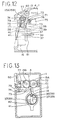
- Fig. 10 is a left side view of second state of the reinforcing bar binding device of the invention.
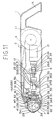
- Fig. 11 is a diagram showing a third state of the reinforcing bar binding device of the invention, at a section of same position as in Fig. 2.
- Fig. 12 is a partial sectional view showing essential parts of a wire feeding mechanism of the reinforcing bar binding device shown in Fig. 11.
- Fig. 13 is a partial sectional view showing a state of the wire feeding mechanism shown in Fig. 12, seen from a forward direction, by omitting the wall portion of the main body.
- Fig. 14 is a diagram showing third and fourth states of the reinforcing bar binding device according to the invention, at a section of same position as in Fig. 2.
- Fig. 15 is a diagram showing third and fourth states of the reinforcing bar binding device according to the invention, at a section of same position as in Fig. 3.
- Fig. 16 is a partial sectional view showing a second male thread member, a second annular portion, a head, and its vicinity, in the second state of the reinforcing bar binding device according to the invention.
- Fig. 17 is a partial sectional view showing the second male thread member, the second annular portion, the head, and its vicinity, in the third and fourth states of the reinforcing bar binding device according to the invention.
- Fig. 18 is a partial sectional view of line XVIII-XVIII in Fig. 16.
- Fig. 19 is a partial sectional view showing other state at same position as in Fig. 18.
- Fig. 20 is a diagram showing the head of the reinforcing bar binding device shown in Fig. 1.
- Fig. 21 is a sectional view of line XXI-XXI in Fig. 20.
- Fig. 22 is a side view of the head shown in Fig. 20.
- Fig. 23 is a top view of the head shown in Fig. 20.
- Fig. 24 is a bottom view of the head shown in Fig. 20.
- Fig. 25 is a schematic perspective view of the state before start of twisting of loop of wire by pin members projecting from the head shown in Fig. 20.
- Fig. 26 is a schematic perspective view showing an intermediate state of twisting of loop of wire by pin members projecting from the head shown in Fig. 20.
- Fig. 27 is a schematic perspective view showing a completed state of twisting of loop of wire by pin members projecting from the head shown in Fig. 20.
- Fig. 28 is a perspective view showing the loop of wire twisted by pin members projecting from the head shown in Fig. 20.
- Fig. 29 is a sectional view showing a conventional reinforcing bar binding device.
- Figs. 1 to 3 show the reinforcing bar binding device according to the invention, which is composed of a main body 1, and a loop forming unit 3 having a pair of grooved curved members 2A, 2B provided at the leading end of the main body 1 in a manner free to open and close.
- the main body 1 comprises a wire feeder 5 for feeding a wire 5 to the loop forming unit 3, and a driving mechanism 6 for cutting the wire 4, opening and closing the curved members, and twisting the wire loop as specifically described below.
- a total of four protrusions 7 are provided at both sides of the curved members 2A, 2B, and a handle 8 is formed in the rear portion of the main body 1.
- the protrusions 7 function to position the intersection of reinforcing bars at the center of twisting, and also function to prevent the curved members 2A, 2B from abutting against the reinforcing bar or other object and being broken.
- the wire feeder 5 consists of a wire reel 11 on which the wire 4 is wound, grooved guide rollers 12 provided rotatably, a wire pay-off unit 16 having a pair of grooved gears 15A, 15B driven by a first motor 14, and a fixed annular guide member 18 having a guide hole 17 for inclining and guiding the wire 4.
- the motor or the combination of the motor and reduction gear is expressed as the motor.
- the driving mechanism 6 comprises a second motor 21, a first male thread member 22, a second male thread member 23, a first annular portion 25, a second annular portion 25, a pair of first pawl members 26A, 26B, a pair of second pawl members 27A, 27B, and head 28.
- the first male thread member 22 is driven by the second motor 21, and is rotated both normally and reversely.
- the second male thread member 23 is disposed parallel to the first male thread member 22, and is coupled through a reduction gear 29, and is rotated in the same directions s the first male thread member 22.
- the first annular portion 24 has plural protrusions 30 extending in the axial direction on the outer circumference, having a female thread portion to be engaged with the first male thread member 22, for moving to the right in Fig. 2, or backward, when the first male thread member 22 normally rotates, relatively to the female thread portion.
- the first annular portion 24 has a plate 31, which does not rotate if the first male thread member 22 and first annular portion 24 rotate but moves in the axial direction together with the first annular portion 24, through a proper bearing. Penetrating through this plate 31, a bar member 32 is provided parallel to the first and second male thread members 22, 23, and the bar member 32 is moved in the axial direction by the plate 31 through coil springs 33, 34 disposed at both sides of the plate 31.
- the second annular portion 25 has a female thread portion 43 (see Figs. 16, 17; to be described later) engaged with the second male thread member 23, and when the second male thread member 23 rotates normally relatively to the female thread portion 43, it moves to the left in Fig. 2, or in the forward direction.
- a cutter 36 and two pin members 37 are projected.
- the first pawl members 26A, 26B are arranged so as to be engaged with the protrusions 30 of the first male thread member 22 at different positions, and the leading ends are thrust by spring so as to always press the first pawl members 26A, 26B.
- the second pawl members 27A, 27B are also arranged so as to be engaged with the protrusions 35A, 35B of the second male thread member 23 at different positions, and the leading ends are thrust by spring so as to always press the second pawl members 27A, 27B.
- the head 28 has a guide groove 38 for sliding the cutter 36, and a guide hole 39 for sliding the pin members 37, and is rotatably inserted into the fixed guide member 18. Together with the second annular portion 25, when the cutter 36 and pin members 37 rotate, the head 28 rotates together.
- a guide groove 40 is opened for guiding the wire 4 guided by the guide hole 17 into the loop forming unit 3 and further into the inlet of the curved member 2A.
- the bottom of the guide grooves 40 is inclined, in Fig. 2, so that the lower side may be positioned forward rather than the upper side, and is formed so that the wire 4 may be inclined in the same direction as the inlet.
- an overhang portion41 projecting over the groove is provided at the outlet of the guide groove 40, and at the advancing side when the head 28 rotates for twisting the loop of the wire 4, an overhang portion41 projecting over the groove is provided.
- the loop forming unit 3 has the curved members 2A, 2B as mentioned above, and they are rotatably supported on the main body 1 by pins 51, 52.
- grooves 53, 54 are formed in the shape tapered in the advancing direction of the wire 4, and in this illustrated example, when the curved members 2A, 2B are closed, the leading end of the curved member 2A gets into the groove 54 of the curved member 2B. As a result, between the groove 53 and groove 54, there is a step difference so that the advancing direction of the wire 4 is lower.
- the curved members 2A, 2B are movable in the opening direction, that is, although the plate 31 and curved members 2A, 2B are coupled indirectly, they are not coupled rigidly, but are coupled with a slight play between them. This play helps to advance the wire 4 smoothly.
- This coil spring 33 also functions as a cushion, if the worker has his hand pinched by the both members by mistake, when closing the curved members 2A, 2B, and also functions to lessen the load acting on the motor or the like if the reinforcing bar is caught between the both members.
- the second motor 21 rotates reversely, the first annular portion 24 advances to move the bar member 32 forward, and at the same time the second annular portion 25 retracts to move the cutter 36 and pin members 37 backward.
- the opening motion of the curved members 2A, 2B is blocked by, for example, reinforcing bar, since the coil spring 34 is provided, the cutter 36 and pin members 37 are allowed to retract.
- the first annular portion 24 and second annular portion 25 return to the initial state described below, and the curved members 2A, 2B are in closed state or incompletely opened state, and hence the coil spring 34 is contracted from the initial state.
- the curved members 2A, 2B are opened by the force of the coil spring 34.
- a stationary guide member 58 for guiding the wire 4 guided by the guide groove 40 into the groove 53.
- the guide surface 58A of this stationary guide member 58 is inclined, and forms a step difference to be lower in the forward direction when advancing from the guide surface 58A to the groove 53.
- This step difference and the step difference formed between the curved members 2A, 2B contribute to smoother advancing of the wire 4, and the stationary guide member 58 helps to curve the wire 4 initially at a greater curvature rate than the curvature rate of the curved member 2A.
- the guide surface 58A of the stationary guide member 58 is preferred to be formed to have a step difference in its width direction.
- the wire 4 coming in with a slope to the plane including the guide groove 40 first advances into the upper stage of the left side of the guide surface 58A as indicated by arrow X in Fig. 4, and in the second turn, it advances to the lower stage at the right side of the guide surface 58A as indicated by arrow Y. That is, without overlapping, the wire 4 is sequentially deviated in the width direction of the guide groove 40, so that a loop is formed smoothly.
- the guide surface 58A may be a slope.
- the wire 4 advances according to arrow X in the first turn, and according to arrow Y in the second turn.
- the loop forming unit 3 has the stationary guide member 58, but this stationary guide member 58 is not always required, but instead of this stationary guide member 58, a guide member of a substantially same shape may be fixed in the curved member 2A so as to operate integrally with the curved member 2A.
- the motors in the reinforcing bar binding device are driven, for example, by batteries not shown herein. Therefore, the first and second motors 14, 21 are DC motors.
- the upper limit of the current flowing in the second motor 21 is determined, and it is designed so that larger current may not flow.
- the flowing current and the torque produced by the DC motor are proportional. Therefore, when the upper limit of the current is determined, the DC motor stops when reaching a specific torque, that is, a torque to such an extent as not to twist the loop too much.
- this stop of rotation is detected by a sensor, not shown, and reverse rotation is started.
- this upper limit should be adjustable because the optimum torque for twisting varies with the diameter of reinforcing bar and operating conditions of the reinforcing bar binding device.
- the reinforcing bar binding device shown in Figs. 1 to 3 shows the first state or the initial state, and the leading end of the wire 4 is positioned at the outlet of the guide hole 17, the first annular portion 24 is positioned to the left in Fig. 2, the second annular portion 25 is positioned to the right, and the curved members 2A, 2B are opened.
- the protrusion 30 of the first annular portion 24 is engaged with the first pawl member 26A, and normal rotation of the first annular portion 24 is defined, and the protrusion 35A of the second annular portion 25 is engaged with the second pawl members 27A, 27B, and the rotation of the second annular portion 25 is defined.
- the loop forming unit 3 is positioned so as to surround the intersection of the reinforcing bar 60. In this case, as mentioned above, it is easy to position the intersection of the reinforcing bar 60 at the center of twisting, by means of the protrusion 7.
- Figs. 6, 7 show detail of the first and second annular portions 24, 25, first and second pawl members 26A, 26B, and 27A, 27B.
- the first pawl member 26A is engaged with the protrusion 30 to define only the normal rotation of the first annular portion 24, and the first pawl member 26B is engaged with the protrusion 30 to define only the reverse rotation of the first annular portion 24.
- the normal rotation is clockwise rotation as indicated by arrow. In the first state, the first pawl member 26B and the protrusion 30 are apart.
- the second pawl member 27B is engaged with the protrusion 35A or protrusion 35B to define the reverse rotation of the second annular portion 25, and the second pawl member 27A is engaged with the protrusion 35A to define the normal rotation of the second annular portion 25.
- the second pawl members 27A, 27B are engaged with the protrusion 35A.
- the protrusion 30 and protrusion 35B are shorter than the moving stroke of the first and second annular portions 24, 25, while the protrusion 35A is at least same in length as the moving stroke of the second annular portion 25.
- Figs. 8 and 9 show the second state of the reinforcing bar binding device.
- the first male thread member 22 is rotated normally by the second motor 21, and the first annular portion 24 defined of normal rotation by the first pawl member 26A moves backward toward the rear stopper 61.
- the plate 31 moves backward, and, at the same time, the bar member 32 moves backward together with the plate 31. Consequently, through the pin 57, the leading ends of the link members 55, 56 engaged with the bar member 32 are attracted backward, and when the bar member 32 reaches the position where the curved members 2A, 2B are closed, the arrival of the bar member 32 is detected by the sensor not shown, so that the second motor 21 is stopped.
- the first annular portion 24 is allowed to rotate normally, but is defined in the reverse rotation.
- Fig. 10 shows the reinforcing bar binding device in a closed state of the curved members 2A, 2B, in which the leading end of the curved member 2A gets into the inlet of the groove 54 of the curved member 2B, so that the wire 4 may advance smoothly from the groove 53 of the curved member 2A into the groove 54 of the curved member 2B.
- Fig. 11 shows a third state of the reinforcing bar binding device.
- the mutually engaged pair of gears 15A, 15B are rotated by the first motor 14, and the wire 4 is sent into the curved members 2A, 2B through the guide hole 17, guide groove 40, and stationary guide member 58.
- the wire 4 is wound plural times, for example, 2.5 times or 3 times, and the wire loop 62 is formed.
- the number of revolutions of the first motor 14 is detected by a sensor not shown, and the first motor 14 stops automatically after operating for the specified number of revolutions.
- the gear 15A is rotatably supported on a support plate 72 by a shaft 71
- the gear 15B is rotatably supported on an L-shaped support member 74 rotatably supported by a pin 73.
- the shaft 71 rotatably penetrates through the support plate 72, and is coupled with a drive shaft 75 rotated by the first motor 14 through a universal joint 76.
- the gear 15A is driven by the first motor 14, and the gear 15B is engaged with the gear 15A so as to rotate synchronously with the gear 15A.
- the gears 15A, 15B have, for example, V-section grooves in the central part.
- a cam 78 is engaged with the end portion beneath the support member 74.
- the cam 78 is rotatable about a shaft 79 penetrating through the wall of the main body 1.
- the shaft 79 is provided with a handle 80 to rotate integrally therewith.
- Figs. 12 and 13 show the state in which the shorter end of the cam 78 is engaged with the lower end of the support member 74, and the end portion is raised by the force of the coil spring 77. In this case, the gears 15A, 15B are kept in engaged state.
- the wire 4 may smoothly advance into the guide hole 17 by the gears 15A, 15B, it is sent out in a state inclined when seen from either sideward or forward direction of the reinforcing bar binding device as shown in Figs. 12 and 13.
- the wire 4 advances in an oblique direction to the guide groove 40, and gets into the stationary guide member 58 through the right side in Fig. 13 at the outlet of the guide groove 40.
- the overhang portion 41 is formed, and this overhang portion 41 prevents the wire from being dislocated from the guide groove 40 effectively.
- Figs. 14 and 15 show the fourth and fifth states of the reinforcing bar binding device.
- the second male thread member 23 together with the first male thread member 22, begins to rotate normally, and the first annular portion 24 rotates normally at the same position, while the second annular portion 25 is defined of the normal rotation by the second pawl member 27A, and moves forward together with the cutter 36 and pin members 37.
- the cutter 36 moves forward, the wire 4 is cut off at the outlet of the guide hole 17, and the pin members 37 project from the front side of the head 28.
- the second male thread member 23 slows down and rotates, so that the cutter 36 advancing force may be greater when cutting off the wire 4.
- the cutter 36 not only cuts off the wire 4, but also advances to the position of pushing out the cut portion of the wire 4 at the head 28 side to the front side of the head 28 (see Fig. 17). This point is further described below.
- the second annular portion 25 abuts against a front stopper 81 provided in the second male thread member 23, and stops advancing. As the second male thread member 23 slows down and rotates, the forward speed of the pin member 37 is reduced, so that the advancing amount may not be excessive.
- the second annular portion 25 hits against the front stopper 81, the second pawl member 27A and the protrusion 35A depart from each other, and the second annular portion 25 is put in normal rotation.
- a flange member 82 is provided around the front end of the male thread portion of the second male thread member 23.
- the second annular portion 25 has a space 83 for inserting this flange member 82 in its inside, and the female thread portion 43 is provided in the rear side opening of this space 83, and its inside diameter is smaller than the outside diameter of the flange member 82.
- the end portion of the female thread portion 43 side of the flange member 82 is the front stopper 81.
- the bar upper member is projecting, and its base part 84 has a section in a shape cutting parallel the both sides of the circular shape, and a front end portion 85 has a section in a circular shape of smaller diameter than the above circular shape, and the base part 84 is continuous to the end portion 85 through a taper 86.
- two leaf springs 87 are disposed parallel across an interval. As shown in Fig. 16, in the third state in which the second annular portion 25 is at the retracted position, as shown in Fig. 18, the leaf spring 87 is kept in a state of pressing the flat portions at both ends of the base part 84 by a spring force.
- the second motor 21 continues to rotate normally.
- the first annular portion 24 rotates normally at the same position
- the second annular portion rotates normally at the same position.
- the pin members 37 rotate together with the head 28, and the loop 62 is twisted.
- the upper limit of the current flowing in the second motor 21 is specified, and when the torque by the second motor 21 reaches a predetermined value, the second motor 21 stops.
- the second motor 21 stops.
- the second motor 21 begins to rotate reversely.
- the second annular portion 25 is defined of its reverse rotation, and it begins to retract along the second male thread support member 23.
- the arrival at this position is detected by a sensor not shown, and the reverse rotation of the second motor 21 is terminated. That is, the reinforcing bar binding device returns to the first state.
- Fig. 20 shows only the head 28 in Fig. 13, and as indicated by twin dot chain line, the loop 62 is twisted in a state being pulled in the direction indicated by solid line arrow in the diagram by the pin members 37.
- the cutter 36 cuts the wire 4, and advances until the end of the wire 4 at the head 28 side is positioned outside of the head 28.
- the front side of the head 28 is formed as a slope so that the side wall of the guide wall 40 may be lower toward the end portion, in the follow-up side portion of the inlet and outlet of the guide groove 40, when the head 28 rotates normally as indicated by broken line arrow in Fig. 20, that is, when twisting the loop 62. More specifically, in Figs. 20 to 24, the sector ends indicated by A and B are sloped so that the groove depth may be smaller toward the end portion of the guide groove 40.
- Figs. 22 to 24 show only the head 28, and the others are omitted, and Figs. 25 to 28 are for clarifying the state of twisting of the loop 62, and other parts not directly relating with twisting are omitted.
- the overhang portion 41 is opened at the follow-up side when rotating for twisting the loop 62, and when twisting is started, the loop 62 is immediately dislocated from the overhang unit 41.
- the loop 62 is dislocated from the guide groove 40 immediately when twisting is started.
- this portion does not project from the twisted portion, and hence the height H in this twisted portion (see Fig. 28) can be set low.
- the cutter 36 is designed to prevent such projection of the wire 4.
- the wire 4 is twisted as being pulled to the both sides of the pin members 37, the height H of the twisted portion is low.
- the second motor 21 stops, and further begins to rotate reversely, and returns to the first state. That is, by the second motor 21, the first male thread member 22 rotates in reverse direction, and the first annular portion 24 define of its reverse rotation by the first pawl member 26B moves forward. As the first annular portion 24 moves forward, the bar member 32 moves back, and the curved members 2A, 2B are opened, so that the reinforcing bar binding device can be dislocated from the reinforcing bar binding portion. At the same time, the second male thread member 23 also begins to rotate reversely, and the second annular portion 25 defined of reverse rotation moves backward, together with the cutter 36 and pin member 37, without rotating from the position shown in Fig. 17.
- the number of protrusions 35B is increased to minimize the angle of reverse rotation of the second annular portion 25.
- the second annular portion 25 retracts, the engagement of the protrusion 35B and second pawl member 27B is cleared, so that the second annular portion 25 is ready to rotate reversely.
- the second annular portion 25 begins to rotate reversely together with the second male thread member 23 rotating reversely.
- the protrusion 35A and pawl member 27B are engaged with each other, and the second annular portion 25 returns to the initial rotation angle sate.
- the second motor 21 when the second annular portion 25 reaches near the position where the engagement state of the protrusion 35B and second pawl member 27B is cleared, the arrival at this position is detected by a sensor not shown, and a stop signal is issued to the second motor 21 rotating reversely.
- the second motor 21 continues t rotate somewhat by inertia after the output of the stop signal, and the leaf spring 87 and base part 84 repeat the state shown in Fig. 18 and Fig. 19, and stop thereafter. That is, the reinforcing bar binding device returns to the initial state shown in Figs. 1 to 3.
- the reinforcing bar binding device works sequentially from the first state to the fifth state, and returns to the first state and stops.
Landscapes
- Engineering & Computer Science (AREA)
- Architecture (AREA)
- Mechanical Engineering (AREA)
- Civil Engineering (AREA)
- Structural Engineering (AREA)
- Basic Packing Technique (AREA)
- Wire Processing (AREA)
- Reinforcement Elements For Buildings (AREA)
Abstract
A reinforcing bar binding machine of a simple construction and a small weight enables the prevention of the exposure of a wire to the outside of concrete, which causes the reinforcing bars to be corroded, by reducing the height of a twisted portion of a wire loop. This machine comprises a machine body (1), and a loop forming unit (3) provided at a front end portion of the machine body (1) and having a pair of groove-carrying bent members (2A, 2B) provided so that the bent members can be opened and closed. The machine body (1) is provided with a wire supply unit (5) for sending a wire (4) to the grooved portions of the bent members (2A, 2B) which are closed so as to enclose crossing portions of reinforcing bars (60), and thereby forming a loop of the wire (4), and a driving mechanism (6) for carrying out in order by one motor (21) the opening and closing of the bent members (2A, 2B), the forward and backward movements of a cutter (36), which is adapted to cut the wire (4) sent to the grooved portions after the loop has been formed, and the forward and backward movements and turning of a pair of spaced and parallel pin members (37) for twisting the formed loop and binding the reinforcing bars (60) by the wire (4).
Description
- The present invention relates to a portable reinforcing bar binding device for binding reinforcing bars, laid down laterally and longitudinally at construction sites, by a wire at their intersections.
- Hitherto, as the means for improving the reinforcing bar binding work at construction sites, a reinforcing bar binding device as shown in Fig. 29 has been proposed (Japanese Patent Publication No. 5-13223). This reinforcing bar binding device has a J-shaped
loop forming unit 102 provided at the leading end of amain body 101, and awire reel 103 provided at the rear part of themain body 101, and theloop forming unit 102 is moved back and forth by areciprocal driving mechanism 104, and awire 105 is sent out from thewire reel 103 by a pair ofpinch rollers 107 driven by amotor 106. Thiswire 105 is further fed into theloop forming unit 102 through a bar-shapedwire twisting unit 110 rotated by awire cutter 108 driven by solenoid or the like, not shown, and amotor 109. The intersection ofreinforcing bars 111 is placed in theloop forming unit 102 in opened state, and theloop forming unit 102 is moved back to close, and thewire 105 is supplied in theloop forming unit 102 to form awire loop 112, and thewire 105 is cut by thewire cutter 108, and thewire loop 112 is twisted by thewire twisting unit 110. - Furthermore, in other reinforcing bar binding device (Japanese Laid-open Utility Model No. 5-3495 (a microfilm of Japanese Utility Model Application No. 3-51320), by a drive mechanism composed of motors, gears, cams, clutches, rollers, and others, a wire is supplied from the wire reel into the J-shaped loop forming unit to form a wire loop, the wire is cut off, and the wire loop is twisted, and in this reinforcing bar binding device, after supplying the wire into the loop forming unit, it is cut off by a cutter provided near the J-shaped leading end, and the wire loop is formed by hooking and twisting by a hook provided in the bar-shaped wire twisting unit.
- In the case of the first reinforcing bar binding device disclosed in Japanese Patent Publication No. 5-13223, four driving devices are used, that is, the
reciprocal driving device 104,motor 106, solenoid, andmotor 109. As a result, the device is not only bulky but also heavy, and the efficiency of the reinforcing bar binding work by this device is, hence, poor. Besides, the loop is twisted by the bar-shapedloop twisting unit 110. That is, the loop is twisted at its one point. Accordingly, only the portion closer to theloop twisting unit 110 is easily twisted, and the height of the twisted portion of the loop is increased. As a result, when the reinforcing bar is buried in concrete, this wire twisted portion is exposed, and corrosion of reinforcing bar may be originated from this exposed portion. Moreover, the intersection of reinforcing bars must be bound by forming loops plural times by the wire, but in the case of this reinforcing bar binding device, it seems difficult to form loops of wire plural times. - In the case of the second reinforcing bar binding device mentioned above, after forming a wire loop, the wire is cut off near the leading end of the J-shaped loop forming unit considerably remote from the loop twisting unit. Accordingly, according to the example disclosed in the microfilm of Japanese Utility Model Application No. 3-51329, at least 3/4 of the periphery of the wire loop is displaced out of the twisted portion of the wire, and it is a wasteful portion.
- In this reinforcing bar binding device, too, same as in the first reinforcing bar binding device, the wire loop is twisted at its one point by the bar-shaped loop twisting unit. Accordingly, same as above, the twisted portion of the wire loop is high, and the wasteful portion is further extended above the twisted portion, and the wire is exposed from the concrete, which gives rise to corrosion of reinforcing bar.
- Moreover, in this reinforcing bar binding device, various mechanical elements are used in the driving mechanism, such as motor, gears, cam, clutch and rollers, and the structure is too much complicated.
- The invention is devised to solve the problems of such prior arts, and it is an object thereof to present a reinforcing bar binding device of simple structure and light weight, capable of preventing exposure of wire from the concrete which may cause corrosion of reinforcing bar, by reducing the height of the twisted portion of wire.
- To solve the problems, a first invention comprises a main body, and a loop forming unit having a pair of curved members with grooves disposed at the leading end of the main body so as to be free to open and close, wherein the main body comprises a wire feeder for forming a loop of wire by feeding a wire into the grooves of the pair of curved members in a closed state so as to enclose the intersection of reinforcing bars, and a driving mechanism incorporating a motor for opening or closing the pair of curved members, and, after forming the loop, advancing and retracting the cutter for cutting off the wire being sent out to the grooves, twisting the formed loop, and advancing, retracting and rotating a pair of pin members disposed at an interval for binding the reinforcing bar by the wire, sequentially.
- In a second invention, the pair of curved members are formed so as to operate by a link mechanism, and the driving mechanism comprises a first male thread member driven and rotated by the motor, a second male thread member disposed parallel to the first male thread member, driven and rotated by the motor through this first male thread member, a first annular portion having a female thread portion to be engaged with the first male thread member, and plural protrusions extending in the axial direction on the outer circumference for moving in the direction departing from the loop forming unit, that is, backward, when the first male thread member rotates normally, relatively to the female thread portion, being coupled to the link mechanism through an intermediate member, for closing the curved members by moving backward, and opening the curved members by moving forward in the direction toward the loop forming unit, a second annular portion having a female thread portion to be engaged with the second male thread member, and plural protrusions extending in the axial direction on the outer circumference for moving forward when the second male thread member rotates relatively along with the normal rotation of the first male thread member, being formed to be free to advance and retract integrally with the cutter and pin members, and to rotate integrally, for advancing the cutter by moving forward to move over the wire cutting position, and projecting the pin members to the position for twisting the loop, a pair of first pawl members to be engaged and disengaged with the protrusions of the first annular portion, for restraining the normal rotation of the first annular portion and allowing to move in a direction along the shaft in a first state which is an initial state before start of reinforcing bar binding work, moving from the position in the first state, hitting against the rear stopper, allowing to move in a forward direction toward the first annular portion restrained of the move in the backward direction, restraining reverse rotation and allowing normal rotation in a second state, and holding the second in third and fourth states, and a fifth state returning to the first state, a pair of second pawl members to be engaged and disengaged with the protrusions of the second annular portion, for restraining the rotation of the second annular portion and allowing to move in an axial direction in the first, second and third states, and allowing rotation of the second male thread member along the normal rotation of the first male member and rotation of the second annular portion in the same direction, restraining the rotation of the second annular portion in the opposite direction thereof, hitting against the front stopper after moving from the position in the third state, and allowing to move in the backward direction toward the second annular portion restrained of the move in the forward direction in the fourth and fifth states, and a head unit having a guide unit for sliding the cutter and pin members, and also having a guide groove for guiding the wire toward the inlet of the loop forming unit on the front surface, being provided rotatably together with the pin members, wherein normal rotation of the first male thread member from the first state in which the first annular portion is at the advanced position and the second annular portion is at the retracted position causes to change to the second and third states, further normal rotation of the first male thread member to the fourth state, further normal rotation of the first male thread member to the fifth state, and the subsequent reverse rotation of the male thread member causes to move to the first state.
- In a third invention, the guide groove of the head unit has an overhang portion projecting above the groove, at the outlet unit and at the advanced side when the head rotates for twisting the loop, and is inclined forward along the wire advancing direction.
- In a fourth invention, the front part of the head unit is formed as a slope so that the side wall of the guide groove may be lower toward the end portion, in the inlet side and outside side follower side portions when the head rotates for twisting the loop.
- In a fifth invention, the loop forming unit comprises a stationary guide member having a guide surface which is inclined in the same direction as the bottom of the inlet of the groove at the inlet side of the groove of the curved member, and forms a step to be low forward in the wire advancing direction.
- In a sixth invention, the curved member has a groove in a shape tapered along the wire advancing direction.
- In a seventh invention, the intermediate member consists of a first member movable integrally with the first annular portion and provided rotatably, relatively to the first annular portion, and a second member for operating the link mechanism directly, being operating in the same direction as the moving direction of the first member, by the first member through a spring whether the first member moves in normal direction or reverse direction.
- In an eighth invention, the wire feeder has a guide member piercing guide hole for guiding the wire into the guide groove, being inclined in the longitudinal direction in a plane parallel to the plane extending in the longitudinal direction to the width direction of the guide groove of the head, at the outlet side of a pair of grooved gears for pinching and sending out the wire.
- In a ninth invention, the motor is operated by a direct-current power source, and is limited in the torque so that its current may be lower than a preset value.
- According to the first invention, which comprises a main body, and a loop forming unit having a pair of curved members with grooves disposed at the leading end of the main body so as to be free to open and close, the main body comprises a wire feeder for forming a loop of wire by feeding a wire into the grooves of the pair of curved members in a closed state so as to enclose the intersection of reinforcing bars, and a driving mechanism incorporating a motor for opening or closing the pair of curved members, and, after forming the loop, advancing and retracting the cutter for cutting off the wire being sent out to the grooves, twisting the formed loop, and advancing, retracting and rotating a pair of pin members disposed at an interval for binding the reinforcing bar by the wire, sequentially.
- Therefore, since the driving mechanism is driven by one motor, the structure is simple and lightweight, and the working efficiency of reinforcing bar binding is enhanced.
- According to the second invention, the pair of curved members are formed so as to operate by a link mechanism, and the driving mechanism comprises a first male thread member driven and rotated by the motor, a second male thread member disposed parallel to the first male thread member, driven and rotated by the motor through this first male thread member, a first annular portion having a female thread portion to be engaged with the first male thread member, and plural protrusions extending in the axial direction on the outer circumference for moving in the direction departing from the loop forming unit, that is, backward, when the first male thread member rotates normally, relatively to the female thread portion, being coupled to the link mechanism through an intermediate member, for closing the curved members by moving backward, and opening the curved members by moving forward in the direction toward the loop forming unit, a second annular portion having a female thread portion to be engaged with the second male thread member, and plural protrusions extending in the axial direction on the outer circumference for moving forward when the second male thread member rotates relatively along with the normal rotation of the first male thread member, being formed to be free to advance and retract integrally with the cutter and pin members, and to rotate integrally, for advancing the cutter by moving forward to move over the wire cutting position, and projecting the pin members to the position for twisting the loop, a pair of first pawl members to be engaged and disengaged with the protrusions of the first annular portion, for restraining the normal rotation of the first annular portion and allowing to move in a direction along the shaft in a first state which is an initial state before start of reinforcing bar binding work, moving from the position in the first state, hitting against the rear stopper, allowing to move in a forward direction toward the first annular portion restrained of the move in the backward direction, restraining reverse rotation and allowing normal rotation in a second state, and holding the second in third and fourth states, and a fifth state returning to the first state, a pair of second pawl members to be engaged and disengaged with the protrusions of the second annular portion, for restraining the rotation of the second annular portion and allowing to move in an axial direction in the first, second and third states, and allowing rotation of the second male thread member along the normal rotation of the first male member and rotation of the second annular portion in the same direction, restraining the rotation of the second annular portion in the opposite direction thereof, hitting against the front stopper after moving from the position in the third state, and allowing to move in the backward direction toward the second annular portion restrained of the move in the forward direction in the fourth and fifth states, and a head unit having a guide unit for sliding the cutter and pin members, and also having a guide groove for guiding the wire toward the inlet of the loop forming unit on the front surface, being provided rotatably together with the pin members, wherein normal rotation of the first male thread member from the first state in which the first annular portion is at the advanced position and the second annular portion is at the retracted position causes to change to the second and third states, further normal rotation of the first male thread member to the fourth state, further normal rotation of the first male thread member to the fifth state, and the subsequent reverse rotation of the male thread member causes to move to the first state.
- Therefore, in addition to the effects of the first invention, when twisting the loop, since the loop is twisted by applying a pulling direction at both sides by the pair of pin members, the height of the twisted portion of the loop is low. Besides, since the cutter is moved beyond the cutting position, when the head is rotated for twisting the loop, the cut portion of the wire is prevented from projecting out of the twisted portion of the loop as being bent by the friction with the peripheral inner wall of the head. As a result, when the reinforcing bar is buried in the concrete, the wire is prevented from being exposed from the concrete, and corrosion of the reinforcing bar can be suppressed.
- According to the third invention, the guide groove of the head unit has an overhang portion projecting above the groove, at the outlet unit and at the advanced side when the head rotates for listing the loop, and is inclined forward along the wire advancing direction.
- Therefore, in addition to the effects of the above inventions, the wire is not dislocated from the guide groove when forming a loop, and the working efficiency is further enhanced.
- According to the fourth invention, the front part of the head unit is formed as a slope so that the side wall of the guide groove may be lower toward the end portion, in the inlet side and outside side follower side portions when the head rotates for twisting the loop.
- Therefore, in addition to the effects of the above inventions, the loop can be twisted smoothly as the loop is dislocated from the guide groove when twisting the loop.
- According to the fifth invention, the loop forming unit comprises a stationary guide member having a guide surface which is inclined in the same direction as the bottom of the inlet of the groove at the inlet side of the groove of the curved member, and forms a step to be low forward in the wire advancing direction.
- Therefore, in addition to the effects of the above inventions, the wire advances easily when forming a loop, the loop is formed smoothly, the wire feeding force can be reduced, and the working efficiency is enhanced, and the device is reduced in size.
- According to the sixth invention, the curved member has a groove in a shape tapered along the dire advancing direction.
- Therefore, in addition to the effects of the above inventions, the wire can be securely guided into the forward groove when forming a loop, and the reliability of loop forming can be enhanced.
- According to the seventh invention, the intermediate member consists of a first member movable integrally with the first annular portion and provided rotatably, relatively to the first annular portion, and a second member for operating the link mechanism directly, being operating in the same direction as the moving direction of the first member, by the first member through a spring whether the first member moves in normal direction or reverse direction.
- Therefore, in addition to the effects of the above inventions, when the curved members are closed, if, for example, the worker has his hand pinched by the curved members by mistake, the spring works as the cushion to prevent injury, or if the reinforcing bar is caught in the curved members, the spring works as the cushion to prevent the motor or driving unit from being overloaded. Still more, since the spring is provided, if the curved members are closed, there is a certain play allowing the curved members to move in the opening direction, and when the wire advanced in the grooves of the curved members, a clearance is formed between the wire and the groove bottom, which helps to form a loop, thereby contributing further to the enhancement of working efficiency and reduction of size of the driving unit. Further, when the curved members are opened, if the curved members hit against obstacle such as reinforcing bar to block the opening action of the curved members, the cutter and pin members operate to return to the initial state, and when the obstacle is cleared, the curved members can be also opened, so that the motor is prevented from being overloaded, too.
- According to the eighth invention, the wire feeder has a guide member piercing guide hole for guiding the wire into the guide groove, being inclined in the longitudinal direction in a plane parallel to the plane extending in the longitudinal direction to the width direction of the guide groove of the head, at the outlet side of a pair of grooved gears for pinching and sending out the wire.
- Therefore, in addition to the effects of the above inventions, the loop can be formed further smoothly.
- According to the ninth invention, the motor is operated by a direct-current power source, and is limited in the torque so that its current may be lower than a preset value.
- Therefore, in addition to the effects of the above inventions, the torque caused by the motor is prevented from becoming excessive to avoid excessive twisting of the loop, while the twisting degree can be kept constant.
- Fig. 1 is a plan view showing a first state of a reinforcing bar binding device according to the invention.
- Fig. 2 is a sectional view of line II-II in Fig. 1.
- Fig. 3 is a sectional view of line III-III in Fig. 1.
- Fig. 4 is a perspective view showing an example of a stationary guide member shown in Fig. 2.
- Fig. 5 is a perspective view showing other example of a stationary guide member shown in Fig. 2.
- Fig. 6 is a partial sectional view showing an example of engaged state of a first annular member and a first pawl member.
- Fig. 7 is a partial sectional view showing an example of engaged state of a second annular member and a second pawl member.
- Fig. 8 is a diagram showing a second state of the reinforcing bar binding device of the invention, at a section of same position as in Fig. 2.
- Fig. 9 is a diagram showing a second state of the reinforcing bar binding device of the invention, at a section of same position as in Fig. 3.
- Fig. 10 is a left side view of second state of the reinforcing bar binding device of the invention.
- Fig. 11 is a diagram showing a third state of the reinforcing bar binding device of the invention, at a section of same position as in Fig. 2.
- Fig. 12 is a partial sectional view showing essential parts of a wire feeding mechanism of the reinforcing bar binding device shown in Fig. 11.
- Fig. 13 is a partial sectional view showing a state of the wire feeding mechanism shown in Fig. 12, seen from a forward direction, by omitting the wall portion of the main body.
- Fig. 14 is a diagram showing third and fourth states of the reinforcing bar binding device according to the invention, at a section of same position as in Fig. 2.
- Fig. 15 is a diagram showing third and fourth states of the reinforcing bar binding device according to the invention, at a section of same position as in Fig. 3.
- Fig. 16 is a partial sectional view showing a second male thread member, a second annular portion, a head, and its vicinity, in the second state of the reinforcing bar binding device according to the invention.
- Fig. 17 is a partial sectional view showing the second male thread member, the second annular portion, the head, and its vicinity, in the third and fourth states of the reinforcing bar binding device according to the invention.
- Fig. 18 is a partial sectional view of line XVIII-XVIII in Fig. 16.
- Fig. 19 is a partial sectional view showing other state at same position as in Fig. 18.
- Fig. 20 is a diagram showing the head of the reinforcing bar binding device shown in Fig. 1.
- Fig. 21 is a sectional view of line XXI-XXI in Fig. 20.
- Fig. 22 is a side view of the head shown in Fig. 20.
- Fig. 23 is a top view of the head shown in Fig. 20.
- Fig. 24 is a bottom view of the head shown in Fig. 20.
- Fig. 25 is a schematic perspective view of the state before start of twisting of loop of wire by pin members projecting from the head shown in Fig. 20.
- Fig. 26 is a schematic perspective view showing an intermediate state of twisting of loop of wire by pin members projecting from the head shown in Fig. 20.
- Fig. 27 is a schematic perspective view showing a completed state of twisting of loop of wire by pin members projecting from the head shown in Fig. 20.
- Fig. 28 is a perspective view showing the loop of wire twisted by pin members projecting from the head shown in Fig. 20.
- Fig. 29 is a sectional view showing a conventional reinforcing bar binding device.
- Referring now to the drawings, preferred embodiments of the invention are described in detail below.
- Figs. 1 to 3 show the reinforcing bar binding device according to the invention, which is composed of a main body 1, and a
loop forming unit 3 having a pair of groovedcurved members - The main body 1 comprises a
wire feeder 5 for feeding awire 5 to theloop forming unit 3, and adriving mechanism 6 for cutting thewire 4, opening and closing the curved members, and twisting the wire loop as specifically described below. In the front portion of the main body 1, that is, at the left end in Fig. 2, a total of fourprotrusions 7 are provided at both sides of thecurved members handle 8 is formed in the rear portion of the main body 1. Theprotrusions 7 function to position the intersection of reinforcing bars at the center of twisting, and also function to prevent thecurved members - The
wire feeder 5 consists of awire reel 11 on which thewire 4 is wound,grooved guide rollers 12 provided rotatably, a wire pay-off unit 16 having a pair ofgrooved gears first motor 14, and a fixedannular guide member 18 having aguide hole 17 for inclining and guiding thewire 4. - In this specification, the motor or the combination of the motor and reduction gear is expressed as the motor.
- The
driving mechanism 6 comprises asecond motor 21, a firstmale thread member 22, a secondmale thread member 23, a firstannular portion 25, a secondannular portion 25, a pair offirst pawl members second pawl members head 28. The firstmale thread member 22 is driven by thesecond motor 21, and is rotated both normally and reversely. The secondmale thread member 23 is disposed parallel to the firstmale thread member 22, and is coupled through areduction gear 29, and is rotated in the same directions s the firstmale thread member 22. - The first
annular portion 24 hasplural protrusions 30 extending in the axial direction on the outer circumference, having a female thread portion to be engaged with the firstmale thread member 22, for moving to the right in Fig. 2, or backward, when the firstmale thread member 22 normally rotates, relatively to the female thread portion. The firstannular portion 24 has aplate 31, which does not rotate if the firstmale thread member 22 and firstannular portion 24 rotate but moves in the axial direction together with the firstannular portion 24, through a proper bearing. Penetrating through thisplate 31, abar member 32 is provided parallel to the first and secondmale thread members bar member 32 is moved in the axial direction by theplate 31 throughcoil springs plate 31. - The second
annular portion 25 has a female thread portion 43 (see Figs. 16, 17; to be described later) engaged with the secondmale thread member 23, and when the secondmale thread member 23 rotates normally relatively to thefemale thread portion 43, it moves to the left in Fig. 2, or in the forward direction. On the outer circumference of the secondannular portion 25,plural protrusions annular member 25, acutter 36 and twopin members 37 are projected. - The
first pawl members protrusions 30 of the firstmale thread member 22 at different positions, and the leading ends are thrust by spring so as to always press thefirst pawl members second pawl members protrusions male thread member 23 at different positions, and the leading ends are thrust by spring so as to always press thesecond pawl members - The
head 28 has aguide groove 38 for sliding thecutter 36, and aguide hole 39 for sliding thepin members 37, and is rotatably inserted into the fixedguide member 18. Together with the secondannular portion 25, when thecutter 36 andpin members 37 rotate, thehead 28 rotates together. In the middle of the end ahead of thehead 28, aguide groove 40 is opened for guiding thewire 4 guided by theguide hole 17 into theloop forming unit 3 and further into the inlet of thecurved member 2A. The bottom of theguide grooves 40 is inclined, in Fig. 2, so that the lower side may be positioned forward rather than the upper side, and is formed so that thewire 4 may be inclined in the same direction as the inlet. At the outlet of theguide groove 40, and at the advancing side when thehead 28 rotates for twisting the loop of thewire 4, an overhang portion41 projecting over the groove is provided. - The
loop forming unit 3 has thecurved members pins curved members grooves wire 4, and in this illustrated example, when thecurved members curved member 2A gets into thegroove 54 of thecurved member 2B. As a result, between thegroove 53 andgroove 54, there is a step difference so that the advancing direction of thewire 4 is lower. - On the other hand, in the
curved members members bar member 32 through apin 57. When thebar member 32 moves forward, that is, to the left in Fig. 2, thecurved members bar member 32 moves backward, thecurved members bar member 32 andplate 31, coil springs 33, 34 are provided, and as theplate 31 moves forward or backward, thebar member 32 moves somewhat later. That is, when the spring force by thecoil spring 33 orcoil spring 34 becomes somewhat large, thebar member 32 begins to move. Therefore, when theplate 31 moves, thecurved members - For example, in the closed state of the
curved members curved members coil spring 33 becomes somewhat large, thecurved members plate 31 andcurved members wire 4 smoothly. - In the absence of the
coil spring 33, when thecurved members curved members link members bar member 32, and firstannular portion 24 is sufficiently high. In actual trial products, when closing thecurved members link members bar member 32 are stopped after moving 12 mm, while the firstannular portion 24 moves by 14 mm. Therefore, when thecurved members coil spring 33 is contracted by 2 mm from the initial state, so that the error in the position and dimension of the members can be allowed. - This
coil spring 33 also functions as a cushion, if the worker has his hand pinched by the both members by mistake, when closing thecurved members - On the other hand, when the
curved members second motor 21 rotates reversely, the firstannular portion 24 advances to move thebar member 32 forward, and at the same time the secondannular portion 25 retracts to move thecutter 36 andpin members 37 backward. In this case, if the opening motion of thecurved members coil spring 34 is provided, thecutter 36 andpin members 37 are allowed to retract. - In this case, the first
annular portion 24 and secondannular portion 25 return to the initial state described below, and thecurved members coil spring 34 is contracted from the initial state. By moving the reinforcing bar binding device and is pulled out of the disturbing reinforcing bar, thecurved members coil spring 34. - Further, at the inlet of the
groove 53 of thecurved member 2A, there is astationary guide member 58 for guiding thewire 4 guided by theguide groove 40 into thegroove 53. Theguide surface 58A of thisstationary guide member 58 is inclined, and forms a step difference to be lower in the forward direction when advancing from theguide surface 58A to thegroove 53. This step difference and the step difference formed between thecurved members wire 4, and thestationary guide member 58 helps to curve thewire 4 initially at a greater curvature rate than the curvature rate of thecurved member 2A. - As shown in Fig. 4, meanwhile, the
guide surface 58A of thestationary guide member 58 is preferred to be formed to have a step difference in its width direction. In this case, thewire 4 coming in with a slope to the plane including theguide groove 40 first advances into the upper stage of the left side of theguide surface 58A as indicated by arrow X in Fig. 4, and in the second turn, it advances to the lower stage at the right side of theguide surface 58A as indicated by arrow Y. That is, without overlapping, thewire 4 is sequentially deviated in the width direction of theguide groove 40, so that a loop is formed smoothly. - Moreover, as shown in Fig. 5, the
guide surface 58A may be a slope. In this case, thewire 4 advances according to arrow X in the first turn, and according to arrow Y in the second turn. - In the case of the reinforcing bar binding device illustrated herein, the
loop forming unit 3 has thestationary guide member 58, but thisstationary guide member 58 is not always required, but instead of thisstationary guide member 58, a guide member of a substantially same shape may be fixed in thecurved member 2A so as to operate integrally with thecurved member 2A. - The motors in the reinforcing bar binding device are driven, for example, by batteries not shown herein. Therefore, the first and
second motors - In the illustrated example, moreover, the upper limit of the current flowing in the
second motor 21 is determined, and it is designed so that larger current may not flow. In the case of a DC motor, the flowing current and the torque produced by the DC motor are proportional. Therefore, when the upper limit of the current is determined, the DC motor stops when reaching a specific torque, that is, a torque to such an extent as not to twist the loop too much. When thesecond motor 21 stops, this stop of rotation is detected by a sensor, not shown, and reverse rotation is started. - Preferably, this upper limit should be adjustable because the optimum torque for twisting varies with the diameter of reinforcing bar and operating conditions of the reinforcing bar binding device.
- Together with the operation of the reinforcing bar binding device, its structure is specifically described below.
- The reinforcing bar binding device shown in Figs. 1 to 3 shows the first state or the initial state, and the leading end of the
wire 4 is positioned at the outlet of theguide hole 17, the firstannular portion 24 is positioned to the left in Fig. 2, the secondannular portion 25 is positioned to the right, and thecurved members protrusion 30 of the firstannular portion 24 is engaged with thefirst pawl member 26A, and normal rotation of the firstannular portion 24 is defined, and theprotrusion 35A of the secondannular portion 25 is engaged with thesecond pawl members annular portion 25 is defined. - In the first state, the
loop forming unit 3 is positioned so as to surround the intersection of the reinforcingbar 60. In this case, as mentioned above, it is easy to position the intersection of the reinforcingbar 60 at the center of twisting, by means of theprotrusion 7. - Figs. 6, 7 show detail of the first and second
annular portions second pawl members first pawl member 26A is engaged with theprotrusion 30 to define only the normal rotation of the firstannular portion 24, and thefirst pawl member 26B is engaged with theprotrusion 30 to define only the reverse rotation of the firstannular portion 24. In Figs. 6, 7, the normal rotation is clockwise rotation as indicated by arrow. In the first state, thefirst pawl member 26B and theprotrusion 30 are apart. Thesecond pawl member 27B is engaged with theprotrusion 35A orprotrusion 35B to define the reverse rotation of the secondannular portion 25, and thesecond pawl member 27A is engaged with theprotrusion 35A to define the normal rotation of the secondannular portion 25. In the first state, thesecond pawl members protrusion 35A. - The
protrusion 30 andprotrusion 35B are shorter than the moving stroke of the first and secondannular portions protrusion 35A is at least same in length as the moving stroke of the secondannular portion 25. - Figs. 8 and 9 show the second state of the reinforcing bar binding device. In this state, the first
male thread member 22 is rotated normally by thesecond motor 21, and the firstannular portion 24 defined of normal rotation by thefirst pawl member 26A moves backward toward therear stopper 61. Further, as the firstannular portion 24 moves backward, theplate 31 moves backward, and, at the same time, thebar member 32 moves backward together with theplate 31. Consequently, through thepin 57, the leading ends of thelink members bar member 32 are attracted backward, and when thebar member 32 reaches the position where thecurved members bar member 32 is detected by the sensor not shown, so that thesecond motor 21 is stopped. - As a result of the first
annular member 24 moving backward, the engagement or thefirst pawl member 26A andprotrusion 30 is cleared, and thefirst pawl member 26B andprotrusion 30 are engaged with each other. Hence, the firstannular portion 24 is allowed to rotate normally, but is defined in the reverse rotation. - When the first
male thread member 22 rotates normally, the secondmale thread member 23 also rotates normally at the same time, and the secondannular portion 25 defined of normal rotation by thesecond pawl member 27B is moved forward. As the secondannular portion 25 moves forward, thecutter 36 andpin member 37 also move forward. - Between the first
male thread member 22 and secondmale thread member 23, areduction gear 29 is placed, and the secondmale thread member 23 is rotated and driven at lower speed than the firstmale thread member 22. Therefore, when thecurved members male thread member 22 also moves together, and the closing force is weakened, so that the operator may not be injured if the hand is caught by mistake between thecurved members second motor 21 itself is small. Still more, by slowing down and rotating the secondmale thread member 23, the rotating torque of the secondmale thread member 23 is increased, so that a greater force may be generated when cutting thewire 4 by thecutter 36 or twisting the loop by thepin member 37 as mentioned below. Moreover, by slowing down and rotating the secondmale thread member 23, the forward moving amount of thecutter 36 andpin members 37 is prevented from being excessive. - Fig. 10 shows the reinforcing bar binding device in a closed state of the
curved members curved member 2A gets into the inlet of thegroove 54 of thecurved member 2B, so that thewire 4 may advance smoothly from thegroove 53 of thecurved member 2A into thegroove 54 of thecurved member 2B. - Fig. 11 shows a third state of the reinforcing bar binding device. In this state, the mutually engaged pair of
gears first motor 14, and thewire 4 is sent into thecurved members guide hole 17,guide groove 40, andstationary guide member 58. Moreover, along thegrooves curved members wire 4 is wound plural times, for example, 2.5 times or 3 times, and thewire loop 62 is formed. The number of revolutions of thefirst motor 14 is detected by a sensor not shown, and thefirst motor 14 stops automatically after operating for the specified number of revolutions. - As shown in Figs. 12 and 13, the
gear 15A is rotatably supported on asupport plate 72 by ashaft 71, and thegear 15B is rotatably supported on an L-shapedsupport member 74 rotatably supported by apin 73. Theshaft 71 rotatably penetrates through thesupport plate 72, and is coupled with adrive shaft 75 rotated by thefirst motor 14 through auniversal joint 76. Directly, thegear 15A is driven by thefirst motor 14, and thegear 15B is engaged with thegear 15A so as to rotate synchronously with thegear 15A. Thegears - In Fig. 13, the upper part of the
support member 74 is always thrust toward thegear 15A by acoil spring 77 supported on the inner wall of the main body 1 at one end portion. That is, thegear 15B is thrust so as to be engaged always with thegear 15A. - In Fig. 13, a
cam 78 is engaged with the end portion beneath thesupport member 74. Thecam 78 is rotatable about ashaft 79 penetrating through the wall of the main body 1. At the outside of the main body 1, theshaft 79 is provided with ahandle 80 to rotate integrally therewith. Figs. 12 and 13 show the state in which the shorter end of thecam 78 is engaged with the lower end of thesupport member 74, and the end portion is raised by the force of thecoil spring 77. In this case, thegears - On the other hand, from the state shown in Figs. 12, 13, rotating the
handle 80, the longer end of thecam 78 is engaged with the end portion, and the end portion moves down, overcoming the force of thecoil spring 77, and thesupport member 74 rotates in the counterclockwise direction in Fig. 13. As a result, the gear 15BV moves in a direction departing from thegear 15A, and the passage for thewire 4 formed by the grooves of thegears wire reel 11, when passing anew wire 4 into thegears gears handle 80 as mentioned above, thewire 4 may b easily guided in between thegears - When departing the
gears handle 80, if the engagement of thegears gear 15B is pressed again to thegear 15A, and it is preferred to leave the engagement slightly. - Besides, in order that the
wire 4 may smoothly advance into theguide hole 17 by thegears - In particular, as shown in Fig. 13, the
wire 4 advances in an oblique direction to theguide groove 40, and gets into thestationary guide member 58 through the right side in Fig. 13 at the outlet of theguide groove 40. - In this right side portion, the
overhang portion 41 is formed, and thisoverhang portion 41 prevents the wire from being dislocated from theguide groove 40 effectively. - Figs. 14 and 15 show the fourth and fifth states of the reinforcing bar binding device. First, in the fourth state, further by the
second motor 21, the secondmale thread member 23, together with the firstmale thread member 22, begins to rotate normally, and the firstannular portion 24 rotates normally at the same position, while the secondannular portion 25 is defined of the normal rotation by thesecond pawl member 27A, and moves forward together with thecutter 36 andpin members 37. As thecutter 36 moves forward, thewire 4 is cut off at the outlet of theguide hole 17, and thepin members 37 project from the front side of thehead 28. As described above, the secondmale thread member 23 slows down and rotates, so that thecutter 36 advancing force may be greater when cutting off thewire 4. Moreover, thecutter 36 not only cuts off thewire 4, but also advances to the position of pushing out the cut portion of thewire 4 at thehead 28 side to the front side of the head 28 (see Fig. 17). This point is further described below. - When the
pin members 37 project to the front side of thehead 28, and thecutter 36 advances to the above position, as shown in Fig. 16, the secondannular portion 25 abuts against afront stopper 81 provided in the secondmale thread member 23, and stops advancing. As the secondmale thread member 23 slows down and rotates, the forward speed of thepin member 37 is reduced, so that the advancing amount may not be excessive. When the secondannular portion 25 hits against thefront stopper 81, thesecond pawl member 27A and theprotrusion 35A depart from each other, and the secondannular portion 25 is put in normal rotation. - Incidentally, as shown in Fig. 16, a
flange member 82 is provided around the front end of the male thread portion of the secondmale thread member 23. - On the other hand, the second
annular portion 25 has aspace 83 for inserting thisflange member 82 in its inside, and thefemale thread portion 43 is provided in the rear side opening of thisspace 83, and its inside diameter is smaller than the outside diameter of theflange member 82. The end portion of thefemale thread portion 43 side of theflange member 82 is thefront stopper 81. - At the forward side of the
flange member 82, the bar upper member is projecting, and itsbase part 84 has a section in a shape cutting parallel the both sides of the circular shape, and afront end portion 85 has a section in a circular shape of smaller diameter than the above circular shape, and thebase part 84 is continuous to theend portion 85 through ataper 86. On the other hand, in the inner wall near the opening of thespace 83, twoleaf springs 87 are disposed parallel across an interval. As shown in Fig. 16, in the third state in which the secondannular portion 25 is at the retracted position, as shown in Fig. 18, theleaf spring 87 is kept in a state of pressing the flat portions at both ends of thebase part 84 by a spring force. Fig. 19 shows a state of theleaf spring 87 being pushed widely by the arc portion of thebase part 84, as only the secondmale thread member 23 is rotated, in the state where thebase part 84 is engaged with theleaf spring 87. By contrast, as shown in Fig. 17, when the secondannular portion 25 is advanced, theleaf spring 87 is departed from thebase part 84, and is not engaged with aleading end 85 having a circular section. These states are described later. - In the fifth state, successively to the fourth state, the
second motor 21 continues to rotate normally. In this case, the firstannular portion 24 rotates normally at the same position, and the second annular portion rotates normally at the same position. At the same time, thepin members 37 rotate together with thehead 28, and theloop 62 is twisted. - As mentioned above, the upper limit of the current flowing in the
second motor 21 is specified, and when the torque by thesecond motor 21 reaches a predetermined value, thesecond motor 21 stops. When stopping of the rotation of thesecond motor 21 is detected by a sensor not shown, thesecond motor 21 begins to rotate reversely. - Since the second
annular portion 25 is defined of its reverse rotation, and it begins to retract along the second malethread support member 23. When the secondannular portion 25 retract to the predetermined position, the arrival at this position is detected by a sensor not shown, and the reverse rotation of thesecond motor 21 is terminated. That is, the reinforcing bar binding device returns to the first state. - The operation is further described by referring to Figs. 20 to 28.
- Fig. 20 shows only the
head 28 in Fig. 13, and as indicated by twin dot chain line, theloop 62 is twisted in a state being pulled in the direction indicated by solid line arrow in the diagram by thepin members 37. - As shown in Fig. 21, the
cutter 36 cuts thewire 4, and advances until the end of thewire 4 at thehead 28 side is positioned outside of thehead 28. - On the other hand, the front side of the
head 28 is formed as a slope so that the side wall of theguide wall 40 may be lower toward the end portion, in the follow-up side portion of the inlet and outlet of theguide groove 40, when thehead 28 rotates normally as indicated by broken line arrow in Fig. 20, that is, when twisting theloop 62. More specifically, in Figs. 20 to 24, the sector ends indicated by A and B are sloped so that the groove depth may be smaller toward the end portion of theguide groove 40. - Incidentally, Figs. 22 to 24 show only the
head 28, and the others are omitted, and Figs. 25 to 28 are for clarifying the state of twisting of theloop 62, and other parts not directly relating with twisting are omitted. - The
overhang portion 41 is opened at the follow-up side when rotating for twisting theloop 62, and when twisting is started, theloop 62 is immediately dislocated from theoverhang unit 41. As mentioned above, moreover, since the end surfaces of thehead 28 indicated by A and B are formed in slopes, theloop 62 is dislocated from theguide groove 40 immediately when twisting is started. Further, as shown in Fig. 21, because of twisting by extruding the end of thewire 4 outward of thehead 28, after theloop 62 is twisted, this portion does not project from the twisted portion, and hence the height H in this twisted portion (see Fig. 28) can be set low. That is, when the end of thewire 4 is positioned inside of theguide groove 38 of thecutter 36, to twist theloop 62, the leading end of thewire 4 is rubbed by the inner wall of theguide member 18 when thehead 28 rotates, and is bent to project from the twisted portion of theloop 62. Thecutter 36 is designed to prevent such projection of thewire 4. - As described herein, since the
wire 4 is twisted as being pulled to the both sides of thepin members 37, the height H of the twisted portion is low. - Since the height H of the twisted portion is lowered, when the reinforcing
bar 60 is covered with concrete, this twisted portion is not exposed from the concrete, and corrosion of reinforcing bar due to such exposure is prevented. - As mentioned above, when a constant torque acts on the second
annular portion 25, and theloop 62 is twisted until the current flowing in thesecond motor 21 reaches the upper limit, thesecond motor 21 stops, and further begins to rotate reversely, and returns to the first state. That is, by thesecond motor 21, the firstmale thread member 22 rotates in reverse direction, and the firstannular portion 24 define of its reverse rotation by thefirst pawl member 26B moves forward. As the firstannular portion 24 moves forward, thebar member 32 moves back, and thecurved members male thread member 23 also begins to rotate reversely, and the secondannular portion 25 defined of reverse rotation moves backward, together with thecutter 36 andpin member 37, without rotating from the position shown in Fig. 17. - Herein, to prevent the twisted portion of the
loop 62 from being loosened when twisting of theloop 62 is over and the secondmale thread member 23 begins to rotate reversely, as shown in Fig. 7, the number ofprotrusions 35B is increased to minimize the angle of reverse rotation of the secondannular portion 25. - Consequently, the second
annular portion 25 retracts, the engagement of theprotrusion 35B andsecond pawl member 27B is cleared, so that the secondannular portion 25 is ready to rotate reversely. Afterwards, as aleaf spring 87 andbase part 84 engage each other, the secondannular portion 25 begins to rotate reversely together with the secondmale thread member 23 rotating reversely. Until the secondannular portion 25 rotates a full turn at maximum, theprotrusion 35A andpawl member 27B are engaged with each other, and the secondannular portion 25 returns to the initial rotation angle sate. As for thesecond motor 21, when the secondannular portion 25 reaches near the position where the engagement state of theprotrusion 35B andsecond pawl member 27B is cleared, the arrival at this position is detected by a sensor not shown, and a stop signal is issued to thesecond motor 21 rotating reversely. Thesecond motor 21 continues t rotate somewhat by inertia after the output of the stop signal, and theleaf spring 87 andbase part 84 repeat the state shown in Fig. 18 and Fig. 19, and stop thereafter. That is, the reinforcing bar binding device returns to the initial state shown in Figs. 1 to 3. - In this way, by one pushbutton operation, the reinforcing bar binding device works sequentially from the first state to the fifth state, and returns to the first state and stops.
Claims (9)
- A reinforcing bar binding device comprising a main body, and a loop forming unit having a pair of curved members with grooves disposed at the leading end of the main body so as to be free to open and close,
wherein the main body comprises a wire feeder for forming a loop of wire by feeding a wire into the grooves of the pair of curved members in a closed state so as to enclose the intersection of reinforcing bars, anda driving mechanism incorporating a motor for opening or closing the pair of curved members, and, after forming the loop, advancing and retracting the cutter for cutting off the wire being sent out to the grooves, twisting the formed loop, and advancing, retracting and rotating a pair of pin members disposed at an interval for binding the reinforcing bar by the wire, sequentially. - A reinforcing bar biding device of claim 1,
wherein the pair of curved members are formed so as to operate by a link mechanism, andthe driving mechanism comprises a first male thread member driven and rotated by the motor,a second male thread member disposed parallel to the first male thread member, driven and rotated by the motor through this first male thread member,a first annular portion having a female thread portion to be engaged with the first male thread member, and plural protrusions extending in the axial direction on the outer circumference for moving in the direction departing from the loop forming unit, that is, backward, when the first male thread member rotates normally, relatively to the female thread portion, being coupled to the link mechanism through an intermediate member, for closing the curved members by moving backward, and opening the curved members by moving forward in the direction toward the loop forming unit,a second annular portion having a female thread portion to be engaged with the second male thread member, and plural protrusions extending in the axial direction on the outer circumference for moving forward when the second male thread member rotates relatively along with the normal rotation of the first male thread member, being formed to be free to advance and retract integrally with the cutter and pin members, and to rotate integrally, for advancing the cutter by moving forward to move over the wire cutting position, and projecting the pin members to the position for twisting the loop,a pair of first pawl members to be engaged and disengaged with the protrusions of the first annular portion, for restraining the normal rotation of the first annular portion and allowing to move in a direction along the shaft in a first state which is an initial state before start of reinforcing bar binding work, moving from the position in the first state, hitting against the rear stopper, allowing to move in a forward direction toward the first annular portion restrained of the move in the backward direction, restraining reverse rotation and allowing normal rotation in a second state, and holding the second in third and fourth states, and a fifth state returning to the first state,a pair of second pawl members to be engaged and disengaged with the protrusions of the second annular portion, for restraining the rotation of the second annular portion and allowing to move in an axial direction in the first, second and third states, and allowing rotation of the second male thread member along the normal rotation of the first male member and rotation of the second annular portion in the same direction, restraining the rotation of the second annular portion in the opposite direction thereof, hitting against the front stopper after moving from the position in the third state, and allowing to move in the backward direction toward the second annular portion restrained of the move in the forward direction in the fourth and fifth states, anda head unit having a guide unit for sliding the cutter and pin members, and also having a guide groove for guiding the wire toward the inlet of the loop forming unit on the front surface, being provided rotatably together with the pin members,
wherein normal rotation of the first male thread member from the first state in which the first annular portion is at the advanced position and the second annular portion is at the retracted position causes to change to the second and third states, further normal rotation of the first male thread member to the fourth state, further normal rotation of the first male thread member to the fifth state, and the subsequent reverse rotation of the male thread member causes to move to the first state. - A reinforcing bar binding device of claim 2, wherein the guide groove of the head unit has an overhang portion projecting above the groove, at the outlet unit and at the advanced side when the head rotates for twisting the loop, and is inclined forward along the wire advancing direction.
- A reinforcing bar binding device of claim 2 or 3, wherein the front part of the head unit is formed as a slope so that the side wall of the guide groove may be lower toward the end portion, in the inlet side and outside side follower side portions when the head rotates for twisting the loop.
- A reinforcing bar binding device of claim 1, wherein the loop forming unit comprises a stationary guide member having a guide surface which is inclined in the same direction as the bottom of the inlet of the groove at the inlet side of the groove of the curved member, and forms a step to be low forward in the wire advancing direction.
- A reinforcing bar binding device of claim 1, wherein the curved member has a groove in a shape tapered along the wire advancing direction.
- A reinforcing bar binding device of claim 2, wherein the intermediate member consists of a first member movable integrally with the first annular portion and provided rotatably, relatively to the first annular portion, and a second member for operating the link mechanism directly, being operating in the same direction as the moving direction of the first member, by the first member through a spring whether the first member moves in normal direction or reverse direction.
- A reinforcing bar binding device of any one of claims 2 to 4, wherein the wire feeder has a guide member piercing guide hole for guiding the wire into the guide groove, being inclined in the longitudinal direction in a plane parallel to the plane extending in the longitudinal direction to the width direction of the guide groove of the head, at the outlet side of a pair of grooved gears for pinching and sending out the wire.
- A reinforcing bar binding device of any one of claims 1 to 8, wherein the motor is operated by a direct-current power source, and is limited in the torque so that its current may be lower than a preset value.
Applications Claiming Priority (3)
| Application Number | Priority Date | Filing Date | Title |
|---|---|---|---|
| JP59622/96 | 1996-03-15 | ||
| JP8059622A JP2923242B2 (en) | 1996-03-15 | 1996-03-15 | Rebar binding machine |
| PCT/JP1996/001831 WO1997034065A1 (en) | 1996-03-15 | 1996-07-01 | Reinforcing bar binding machine |
Publications (2)
| Publication Number | Publication Date |
|---|---|
| EP0829596A1 true EP0829596A1 (en) | 1998-03-18 |
| EP0829596A4 EP0829596A4 (en) | 1999-01-27 |
Family
ID=13118536
Family Applications (1)
| Application Number | Title | Priority Date | Filing Date |
|---|---|---|---|
| EP96921144A Withdrawn EP0829596A4 (en) | 1996-03-15 | 1996-07-01 | Reinforcing bar binding machine |
Country Status (8)
| Country | Link |
|---|---|
| US (1) | US5983473A (en) |
| EP (1) | EP0829596A4 (en) |
| JP (1) | JP2923242B2 (en) |
| KR (1) | KR19990014758A (en) |
| CN (1) | CN1122617C (en) |
| NO (1) | NO975236D0 (en) |
| TW (1) | TW308624B (en) |
| WO (1) | WO1997034065A1 (en) |
Cited By (5)
| Publication number | Priority date | Publication date | Assignee | Title |
|---|---|---|---|---|
| WO2001094206A1 (en) * | 2000-06-06 | 2001-12-13 | Kim Michael Jensen | A method and an apparatus for twisting and tightening a wire |
| WO2004083559A1 (en) * | 2003-03-18 | 2004-09-30 | Peter Hoyaukin | Method and machine for binding elongate objects together |
| CN100398768C (en) * | 2003-03-18 | 2008-07-02 | 彼特·瓦约基 | Method and machine for binding elongate objects together |
| US8607696B2 (en) | 2007-11-20 | 2013-12-17 | Jbj Mechatronic Aps | Binding apparatus |
| US9255415B2 (en) | 2009-05-27 | 2016-02-09 | Jbj Mechantronic Aps | Binding apparatus |
Families Citing this family (44)
| Publication number | Priority date | Publication date | Assignee | Title |
|---|---|---|---|---|
| AU2002318747B2 (en) * | 2001-07-19 | 2008-02-21 | Max Co., Ltd | Reinforcing steel bar tying machine |
| AU2002335474B2 (en) | 2001-09-28 | 2007-08-30 | Max Kabushiki Kaisha | Reinforcement binding machine, reel, and method of detecting rotation of reel |
| JP3624873B2 (en) * | 2001-10-29 | 2005-03-02 | マックス株式会社 | Binding wire twisting device for reinforcing bar binding machine |
| KR100519099B1 (en) * | 2002-06-11 | 2005-10-06 | 주식회사 하나 | An auto-binding apparatus for reinforcing bar, and a wire using therein |
| CN100482909C (en) * | 2003-03-01 | 2009-04-29 | 查尔斯·T·布雷克特 | Steel cable bolt |
| JP4211059B2 (en) * | 2004-01-09 | 2009-01-21 | マックス株式会社 | Reinforcing bar binding machine, wire reel and wire reel identification method |
| JP4396384B2 (en) * | 2004-05-07 | 2010-01-13 | マックス株式会社 | Rebar binding machine |
| JP4548584B2 (en) * | 2004-07-16 | 2010-09-22 | マックス株式会社 | Rebar binding machine |
| US7069962B2 (en) * | 2004-08-27 | 2006-07-04 | Dara Cheng | Wire cutting and twisting tool with spool assembly and manual wire feeding mechanism |
| CN105386602B (en) * | 2005-10-10 | 2019-05-17 | 胡斯华纳有限公司 | For by binding objects to equipment together |
| JP4961808B2 (en) * | 2006-04-05 | 2012-06-27 | マックス株式会社 | Rebar binding machine |
| CN100532763C (en) * | 2007-04-18 | 2009-08-26 | 沈伟强 | Hand-hold electric reinforced bar tying machine |
| JP5126101B2 (en) * | 2008-05-19 | 2013-01-23 | マックス株式会社 | Rebar binding machine |
| JP5149127B2 (en) * | 2008-11-08 | 2013-02-20 | 秀明 石橋 | Rebar binding machine |
| US9597724B2 (en) | 2010-09-02 | 2017-03-21 | Jon R. Kodi | Wire twisting tools and methods |
| CN102390606B (en) * | 2011-07-22 | 2013-09-25 | 孙激扬 | Steel bar bundling mechanical hand and special buckle element thereof |
| DE102013222924A1 (en) * | 2013-11-11 | 2015-05-28 | Hellermann Tyton Gmbh | Portable cable tie tool |
| CN104073936B (en) * | 2014-07-10 | 2016-06-08 | 天津赛象科技股份有限公司 | Head unit pricked automatically by Steel Traveler |
| JP6417772B2 (en) | 2014-07-31 | 2018-11-07 | マックス株式会社 | Rebar binding machine |
| WO2017014270A1 (en) * | 2015-07-22 | 2017-01-26 | マックス株式会社 | Binding machine |
| JP6798167B2 (en) * | 2015-07-22 | 2020-12-09 | マックス株式会社 | Cable ties |
| JP6566310B2 (en) * | 2015-07-22 | 2019-08-28 | マックス株式会社 | Binding machine |
| PL3327223T3 (en) | 2015-07-22 | 2020-09-07 | Max Co., Ltd. | Binding machine |
| CN105460260B (en) * | 2016-01-04 | 2019-11-22 | 深圳市施威德自动化科技有限公司 | A tool for automatic cable ties in narrow spaces |
| SE539617C2 (en) * | 2016-02-12 | 2017-10-17 | Construction Tools Pc Ab | Knot plate for a sewing machine and a sewing machine comprising the knot plate |
| DE102016214733A1 (en) * | 2016-08-09 | 2018-02-15 | Robert Bosch Gmbh | Twisting device for a portable machine tool |
| JP6926446B2 (en) * | 2016-11-10 | 2021-08-25 | マックス株式会社 | Cable ties |
| WO2018131218A1 (en) | 2017-01-10 | 2018-07-19 | 株式会社マキタ | Binding machine |
| CN106644551B (en) * | 2017-02-22 | 2023-06-16 | 广东顺德华焱电子科技有限公司 | Service life testing device of reinforcing steel bar binding machine |
| SE541178C2 (en) * | 2017-09-08 | 2019-04-23 | Skanska Sverige Ab | A tool, a system and a method for manufacturing of a reinforcement bar structure |
| CN108678386B (en) * | 2018-07-11 | 2023-11-24 | 山东万世机械科技有限公司 | Reinforcing steel bar binding machine |
| WO2020093380A1 (en) * | 2018-11-09 | 2020-05-14 | 广东顺德华焱电子科技有限公司 | Rebar bundling machine and bundling control device thereof and bundling control method therefor |
| JP7268386B2 (en) * | 2019-02-13 | 2023-05-08 | マックス株式会社 | binding machine |
| EP4545732A3 (en) | 2019-03-11 | 2025-05-07 | Max Co., Ltd. | Binding machine |
| JP7367313B2 (en) * | 2019-03-11 | 2023-10-24 | マックス株式会社 | tying machine |
| JP6887619B2 (en) * | 2019-08-05 | 2021-06-16 | マックス株式会社 | Cable ties |
| CN110984587B (en) * | 2019-11-22 | 2021-11-16 | 上安实业江苏有限公司 | Reinforcing bar binding device for building field |
| JP7427994B2 (en) * | 2020-02-10 | 2024-02-06 | マックス株式会社 | Binding machine |
| JP7528618B2 (en) | 2020-07-31 | 2024-08-06 | マックス株式会社 | Binding machine |
| JP7632020B2 (en) * | 2020-07-31 | 2025-02-19 | マックス株式会社 | Binding machine |
| CN114776026B (en) * | 2022-06-17 | 2022-09-13 | 中铁九局集团有限公司 | Adjustable binding mechanism for steel bar binding robot |
| JP2024063274A (en) * | 2022-10-26 | 2024-05-13 | マックス株式会社 | Binding machine |
| CN115822269B (en) * | 2022-12-16 | 2025-07-15 | 台州市新大陆电子科技有限公司 | A steel bar bundling machine capable of ejecting wire rings |
| CN115788058B (en) * | 2022-12-16 | 2026-05-12 | 台州市新大陆电子科技有限公司 | Reinforcing steel bar binding machine for cutting wires by wire winding inner sleeve |
Family Cites Families (11)
| Publication number | Priority date | Publication date | Assignee | Title |
|---|---|---|---|---|
| AT349861B (en) * | 1976-05-25 | 1979-04-25 | Evg Entwicklung Verwert Ges | BINDING TOOL FOR TWISTING THE FREE ENDS OF A BINDING WIRE AND LATTICE TYING MACHINE WITH SUCH TOOLS |
| US4252157A (en) * | 1979-01-09 | 1981-02-24 | Takigawa Kogyo Co., Ltd. | Automatic bundling apparatus |
| US4354535A (en) * | 1980-04-21 | 1982-10-19 | Powell Robert Y | Hand-held automatic wire binding tool |
| US4362192A (en) * | 1981-03-05 | 1982-12-07 | Furlong Donn B | Wire tying power tool |
| JPS61191764A (en) * | 1985-02-18 | 1986-08-26 | 湯口 貞雄 | Apparatus for bundling iron bars |
| KR950005011B1 (en) * | 1985-09-24 | 1995-05-17 | 스타이너 운트 비엔쯔 악티엔 게젤샤프트 | Process and device for connecting two rods |
| JPH04201807A (en) * | 1990-11-28 | 1992-07-22 | Fujita Corp | Device for tightening binding wire |
| JPH0513223A (en) * | 1991-07-01 | 1993-01-22 | Alps Electric Co Ltd | Magnetic head |
| JP3393684B2 (en) * | 1993-08-16 | 2003-04-07 | 株式会社エスディーコーポレーション | Article binding method and binding apparatus |
| US5431196A (en) * | 1994-01-03 | 1995-07-11 | Belcan Specialty Equipment Engineering Division Of Belcan Engineering Groups, Inc. | Power rebar tying tool |
| JP2817635B2 (en) * | 1994-10-17 | 1998-10-30 | マックス株式会社 | Winding guide device for binding wires in rebar binding machines |
-
1996
- 1996-03-15 JP JP8059622A patent/JP2923242B2/en not_active Expired - Fee Related
- 1996-07-01 WO PCT/JP1996/001831 patent/WO1997034065A1/en not_active Ceased
- 1996-07-01 CN CN96193940A patent/CN1122617C/en not_active Expired - Fee Related
- 1996-07-01 US US08/930,612 patent/US5983473A/en not_active Expired - Fee Related
- 1996-07-01 EP EP96921144A patent/EP0829596A4/en not_active Withdrawn
- 1996-07-01 KR KR1019970708100A patent/KR19990014758A/en not_active Withdrawn
- 1996-08-30 TW TW085107985A patent/TW308624B/en active
-
1997
- 1997-11-14 NO NO975236A patent/NO975236D0/en not_active Application Discontinuation
Non-Patent Citations (2)
| Title |
|---|
| No further relevant documents disclosed * |
| See also references of WO9734065A1 * |
Cited By (8)
| Publication number | Priority date | Publication date | Assignee | Title |
|---|---|---|---|---|
| WO2001094206A1 (en) * | 2000-06-06 | 2001-12-13 | Kim Michael Jensen | A method and an apparatus for twisting and tightening a wire |
| WO2004083559A1 (en) * | 2003-03-18 | 2004-09-30 | Peter Hoyaukin | Method and machine for binding elongate objects together |
| CN100398768C (en) * | 2003-03-18 | 2008-07-02 | 彼特·瓦约基 | Method and machine for binding elongate objects together |
| RU2340749C2 (en) * | 2003-03-18 | 2008-12-10 | Петер ХОЯУКИН | Extended elements attachment method and mechanism |
| US8047239B2 (en) | 2003-03-18 | 2011-11-01 | Tymatic Limited | Method and machine for binding elongate objects together |
| US8607696B2 (en) | 2007-11-20 | 2013-12-17 | Jbj Mechatronic Aps | Binding apparatus |
| RU2513552C2 (en) * | 2007-11-20 | 2014-04-20 | Йбй Мекатроник Апс | Bonding device |
| US9255415B2 (en) | 2009-05-27 | 2016-02-09 | Jbj Mechantronic Aps | Binding apparatus |
Also Published As
| Publication number | Publication date |
|---|---|
| KR19990014758A (en) | 1999-02-25 |
| CN1122617C (en) | 2003-10-01 |
| CN1184521A (en) | 1998-06-10 |
| EP0829596A4 (en) | 1999-01-27 |
| TW308624B (en) | 1997-06-21 |
| JPH09250205A (en) | 1997-09-22 |
| US5983473A (en) | 1999-11-16 |
| NO975236L (en) | 1997-11-14 |
| JP2923242B2 (en) | 1999-07-26 |
| NO975236D0 (en) | 1997-11-14 |
| WO1997034065A1 (en) | 1997-09-18 |
Similar Documents
| Publication | Publication Date | Title |
|---|---|---|
| US5983473A (en) | Reinforcing bar binding machine | |
| US4834148A (en) | Reinforcement binding machine | |
| EP0886020B1 (en) | A wire twisting device for use in a reinforcement binding machine | |
| US12215511B2 (en) | Binding machine | |
| TW201834932A (en) | Binding machine capable of truly removing the wire when being deviated from the feeding path and curled | |
| JP7661762B2 (en) | Binding machine | |
| JP7718464B2 (en) | Binding machine | |
| JP7647967B2 (en) | Binding machine | |
| JP6972552B2 (en) | Cable ties | |
| KR102924999B1 (en) | Binding machine | |
| EP0952278A2 (en) | Safety device for a reinforcing bars binding machine | |
| JPH07275983A (en) | Rebar binding machine | |
| JP6972551B2 (en) | Cable ties | |
| JP2570696Y2 (en) | Actuation mechanism of torsion hook of binding machine | |
| JP7652311B2 (en) | Binding machine | |
| JPH07284870A (en) | Reinforcing bar bundling machine | |
| CN219528452U (en) | Toggle lever braking type bundling machine | |
| CN111688970B (en) | strapping machine | |
| JPH07275982A (en) | Rebar binding machine | |
| JP2026062040A (en) | Binding machine | |
| KR960013081B1 (en) | Wire binder | |
| EP4332326A1 (en) | Binding machine | |
| JPH0321788Y2 (en) | ||
| JP2024063274A (en) | Binding machine | |
| JPH07277308A (en) | Fastener supply and cutting mechanism in tying machine |
Legal Events
| Date | Code | Title | Description |
|---|---|---|---|
| PUAI | Public reference made under article 153(3) epc to a published international application that has entered the european phase |
Free format text: ORIGINAL CODE: 0009012 |
|
| AK | Designated contracting states |
Kind code of ref document: A1 Designated state(s): AT CH DE DK ES FI FR GB IT LI LU NL PT SE |
|
| 17P | Request for examination filed |
Effective date: 19980318 |
|
| A4 | Supplementary search report drawn up and despatched |
Effective date: 19981211 |
|
| AK | Designated contracting states |
Kind code of ref document: A4 Designated state(s): AT CH DE DK ES FI FR GB IT LI LU NL PT SE |
|
| STAA | Information on the status of an ep patent application or granted ep patent |
Free format text: STATUS: THE APPLICATION IS DEEMED TO BE WITHDRAWN |
|
| 18D | Application deemed to be withdrawn |
Effective date: 20020201 |